Garmin Force User & Maintenance Manual
Trolling motor
Hide thumbs
Also See for Force:
- Installation manual ,
- Field service manual (84 pages) ,
- Replacement instructions manual (22 pages)
Table of Contents
Advertisement
Quick Links
Download this manual
See also:
Owner's Manual
FORCE
TROLLING MOTOR
™
USER MAINTENANCE MANUAL
Tools, Supplies, and Equipment Needed
The tools, supplies, and equipment needed to service and repair
the trolling motor depend on the service or repair needed. Not all
of the items listed are applicable for every procedure.
Tools, Supplies, and Equipment Needed for
Maintenance
When performing routine maintenance, you must have the
following tools and supplies.
• #2 Phillips screwdriver
• 4 mm and 3 mm hex bits or wrenches
• 10 and 15 mm sockets
9
•
/
in. socket
16
◦ For removing the propeller
◦ A 15 mm socket is acceptable, if necessary
• Replacement anodes (010-12832-35)
• Wire brush
• Silicone lubricating grease
• Non-stick, dry-film lubricant (such as DuPont
Lubricant with Teflon
®
)
• Dielectric grease
• Isopropyl alcohol (for cleaning areas before applying touch-
up paint)
• Liquid polyurethane paint (for touching up nicks and
scratches)
Tools, Supplies, and Equipment Needed for Repair
When performing repair or replacement procedures, you must
have the following tools and supplies.
• Suitable workbench or table
◦ Must be at least 8 ft. long for working on the 50 in. models
◦ Must be at least 10 ft. long for working on the 57 in.
models
• #1 Phillips screwdriver
• #2 Phillips screwdriver
• 3 mm and 4 mm and 8 mm hex bits or wrenches
• 10 and 15 mm socket
9
•
/
in. socket
16
◦ For removing the propeller
◦ A 15 mm socket is acceptable, if necessary
• 36 mm or adjustable wrench (for replacing the coil cable)
• Torque wrench
◦ With 4 mm and 8 mm hex bits
◦ Capable of measuring torque from 5 kgf-cm (4.3 lbf-in) to
55 N-m (40.5 lbf-in.)
• Silicone lubricating grease (for replacing the latching
mechanism)
• Needle-nose pliers
• Dielectric grease (for replacing the power cable or coil cable)
• Shaft and motor hardware service kit
◦ S00-01000-35
◦ For replacing the shaft or propeller drive motor
• Metal parts accessory kit
◦ S00-01000-20
◦ Contains all of the metal parts, such as brackets and
screws, that may be needed when performing repairs
• Plastic parts accessory kit
◦ S00-01000-46
◦ Contains all of the plastic parts, such as washers and
bushings, that may be needed when performing repairs
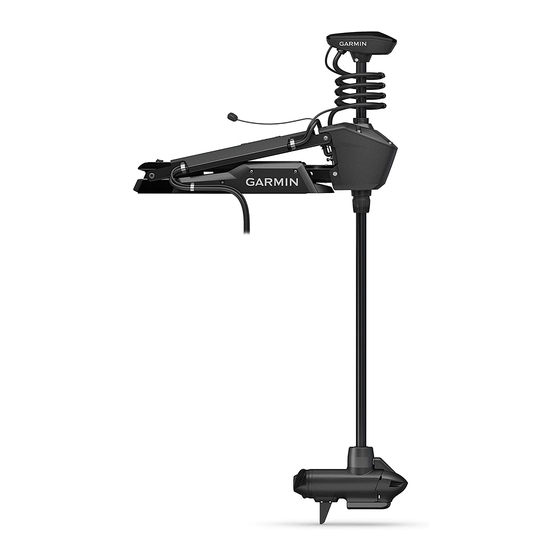
Overview and Part Locations
Item
™
Dry Film
Item
Maintenance Needs and Schedule
Use extreme care when following the procedures in this section.
Some maintenance tasks require you to move the motor from
the stowed to the deployed position multiple times, which
presents a potential for hands or fingers to be crushed by the
weight of the motor.
Description
Shaft cap
Coil cable (and transducer cable)
Power cable (and transducer cable)
Display panel
Steering servo housing
Depth-adjustment collar
Shaft
Drive motor and propeller
Description
Upper link of the mount
Lower link of the mount
Mount base
CAUTION
November 2019
190-02521-05_0B
Advertisement
Table of Contents

Related Manuals for Garmin Force


Summary of Contents for Garmin Force
- Page 1 • Metal parts accessory kit ◦ S00-01000-20 FORCE TROLLING MOTOR ™ ◦ Contains all of the metal parts, such as brackets and screws, that may be needed when performing repairs USER MAINTENANCE MANUAL • Plastic parts accessory kit ◦ S00-01000-46 Tools, Supplies, and Equipment Needed ◦...
- Page 2 Apply a silicone lubricating grease to the locking mechanisms NOTICE and the channels. After using the motor in salt water or brackish water, you must rinse off the entire motor with fresh water, and apply a water- Pull and release the pull cable a number of times to move the based silicone spray using a soft cloth.
- Page 3 Using a 3 mm hex bit or wrench, remove the screw and anode on the front of the motor. Move the motor from the stowed to the deployed position and back a number of times to distribute the lubricant. Examine the anode, and complete an action: If necessary, apply additional lubricant and repeat the •...
- Page 4 Using a 4 mm hex bit or wrench, remove the two screws that and replacement procedures. secure the mount bumper to the mount base. To order the service parts listed in this manual, contact Garmin ® at 1-800-800-1020 or go to support.garmin.com...
-
Page 5: Table Of Contents
Shaft and Cable Parts Item Description Service Part Number Details Power cable S00-01000-22 Removing the Power Cable from the Steering Servo Housing, page 21 Shaft cap S00-01000-12 The service kit contains the internal hardware, cable grip, and grommet. Removing the Shaft Cap, page 11 Coil cable S00-01000-48 Removing the Coil Cable from the Steering Servo Housing, page 22... -
Page 6: Item Description Service Part Number
Transducer: 010-12832-20 One of two parts included with a replacement nose cone. No transducer: 010-12832-22 (Replacing the Nose Cone, page Transducer Contact Garmin support for The replacement transducer and transducer replacement kit are sold replacement transducer options. separately. Transducer replacement kit:... - Page 7 Mount Parts Item Description Service Part Number Details Lower gas spring arm and shaft S00-01000-18 Disconnecting the Lower Gas Spring, page 17 stabilizer Lower gas spring (deploy) S00-01000-37 Disconnecting the Lower Gas Spring, page 17 Mount lower link Lower link and latching components assembled, Removing the Lower Link from the Mount Base, 50 in.
- Page 8 Mount Base Parts Item Description Service Part Number Details Mount base rails 50 in. model: S00-01000-33 Replacing the Mount Rails, page 25 57 in. model: S00-01000-34 Mount base shrouds S00-01000-14 Replacing the Mount Shrouds, page 24 Motor bumper S00-01000-19 Replacing the Mount Bumper, page 25 Mount base 50 in.
- Page 9 Feed the other end of the pull cable through the steering Push the pull cable up from the bottom of the handle, and servo housing, routing the cable between the upper link of remove the R-pin the mount and the pivot pin. Pull the cable through the washer and the bottom of the handle.
- Page 10 TIP: To determine the right (starboard) side of the mount, Using a 3 mm hex bit or wrench, remove the four screws stand in a location where you can read the information on the that secure the two brackets to the mount on both sides of display panel.
-
Page 11: Removing The Shaft Cap
You should keep these screws in a safe place, because you must use them when reconnecting the cables. Release the latch and pull the connectors apart to disconnect the data cable. Removing the Transducer Cable from the Shaft Cap Before you can remove the transducer cable from the shaft cap, you must open the shaft cap (Opening the Shaft Cap, page 11). -
Page 12: Removing The Propeller Drive Motor And Nose Cone From The Shaft
Lift up on the shaft cap to disconnect it from the shaft. Removing the Skeg and Nose Cone Using a 4 mm hex bit or wrench, remove the four screws Pull the cables from the shaft completely through the shaft that secure the skeg to the propeller drive motor. - Page 13 The shaft and motor hardware service kit contains a new cable gland and recessed nut. Disassembling the Nose Cone Before you can disassemble the nose cone, you must remove the skeg and nose cone from the propeller drive motor (Removing the Skeg and Nose Cone, page 12).
- Page 14 Install the nose cone and skeg on the propeller drive motor (Installing the Nose Cone and Skeg, page 15). Installing the Nose Cone and Transducer in the Shaft NOTICE The shaft and motor hardware service kit contains new seals. You should use the new parts from the kit instead of reusing the seals you removed with the nose cone and transducer.
- Page 15 Gently pull the ends of the power and data cables as you feed them the rest of the way through the shaft. NOTICE Using a permanent marker, mark the measured location on When feeding the cables, you must pull on the cable and not the cable on the cable connectors.
- Page 16 Using a 4 mm hex bit or wrench, secure the front of the nose NOTE: The shaft is keyed to fit in the steering servo housing cone to the propeller drive motor using the existing two one way only. screws Tighten the depth adjustment collar on the base of the steering servo housing Installing the Shaft Cap...
- Page 17 NOTE: If the cables are stacked incorrectly, you cannot close the shaft cap cover. Place the stacked cables over the stand outs in the shaft cap. Lift the lower gas spring clevis off of the safety rod Replacing the Lower Gas Spring Before you can replace the lower gas spring, you must disconnect it from the mount (Disconnecting the Lower Gas...
- Page 18 With the motor in the deployed position, disconnect the cable from the display panel on the upper link of the mount Lift the upper gas spring clevis off of the safety rod Replacing the Upper Gas Spring Using an 4 mm hex bit or wrench, remove a screw and Before you can replace the upper gas spring, you must washer from one side of the upper pin...
- Page 19 NOTE: This procedure is best performed with two people. Slide the safety rods away from the steering servo to release the lower pivot pin. NOTE: The two safety rods don't need to move very far to release the lower pivot pin. If either gas spring is still connected to the lower link, however, the safety rods lock the lower pivot pin in place, and it cannot be removed.
- Page 20 Securing the Upper Gas Spring Push the safety rod toward the steering servo housing as Pivot the upper link of the mount forward. far as possible to lock the lower pivot pin in place. Tip the top of the steering servo housing inward so the holes on the upper link and the housing align.
-
Page 21: Removing The Power Cable From The Steering Servo Housing
NOTE: The connector is keyed to fit into the port one way only, and will fit easily when aligned correctly. Do not force the connector into the port. Securing the Lower Gas Spring Transition the trolling motor from the deployed to the stowed position. -
Page 22: Removing The Coil Cable From The Steering Servo Housing
tighten the three screws to 20 kgf-cm (17.4 lbf-in) Reconnect the power cable (Reconnecting the Power Cable, page 21). Removing the Coil Cable from the Shaft Cap Before you can remove the coil cable from the shaft cap, you must disconnect the cables in the shaft cap (Disconnecting the Cables in the Shaft Cap, page 11). -
Page 23: Mount Base
Open the cable clips to remove the position-sensor cable. Place a plastic washer that you removed with the original upper link or a washer supplied with the replacement upper Pinch the tabs on the side of the display panel, and push it link between the upper link and the mount base. -
Page 24: Replacing The Mount Base
If it is still connected, remove the pull cable from the latching Push the pin into the mount base, feeding it through one mechanism (Removing the Pull Cable, page side of the lower link and shaft stabilizer. Using a pair of needle-nose pliers, remove the pins that secure the latch bars to the central rod. -
Page 25: Replacing The Mount Rails
, the Garmin logo, and ActiveCaptain ® are trademarks of Garmin Ltd. or its subsidiaries, registered in the USA and other countries. Force ™ is a trademark of Garmin Ltd. or its subsidiaries. These trademarks may not be used without the express permission of Garmin. - Page 26 © 2019 Garmin Ltd. or its subsidiaries support.garmin.com...
Need help?
Do you have a question about the Force and is the answer not in the manual?
Questions and answers