Garmin FORCE KRAKEN Installation Manual
- Owner's manual (34 pages) ,
- Quick start manual (21 pages) ,
- Replacement instructions manual (14 pages)
Advertisement
Getting Started

See the Important Safety and Product Information guide in the product box for product warnings and other important information.
Failure to install this device according to these instructions could result in personal injury, damage to the vessel or device, or poor product performance.
Do not run the motor when the propeller is out of the water. Contact with the rotating propeller may result in severe injury.
Do not use the motor in areas where you or other people in the water may come into contact with the rotating propeller, which could result in severe injury.
Always disconnect the motor from the battery before handling or working with the propeller, propeller drive motor, electrical connections, or electronics enclosures to avoid serious injury or death.

For the best possible performance and to avoid potential injury, damage to the device, or damage to your vessel, installation by a qualified marine installer is recommended.
To avoid possible personal injury, always wear safety goggles, ear protection, and a dust mask when drilling, cutting, or sanding.
When stowing or deploying the motor, be aware of the risk of entrapment or pinching from moving parts, which can result in personal injury.
When stowing or deploying the motor, maintain stable footing and be aware of slick surfaces around the motor. Losing your footing while stowing or deploying the motor may result in injury.
 NOTICE
When drilling or cutting, always check what is on the opposite side of the surface to avoid damaging the vessel.
Tools and Supplies Needed
- Drill and a 11/32 in. (9 mm) drill bit
- #2 Phillips screwdriver
- 4 mm hex bit or wrench
- 1/2 in. (13 mm) socket
- Torque wrench
- Circuit breaker rated for continuous 60 A
- Trolling motor plug and receptacle rated for 60 A or greater (optional)
- 6, 4, or 2 AWG (16, 25, or 35 mm2) wire for extended runs of the power cable
- Solder and heat-shrink tubing, if extending the power cable
- Stainless steel pan head 5/16-20 (M8x1) bolts (if the included bolts are not long enough to mount the motor to the deck)
Installation Preparation
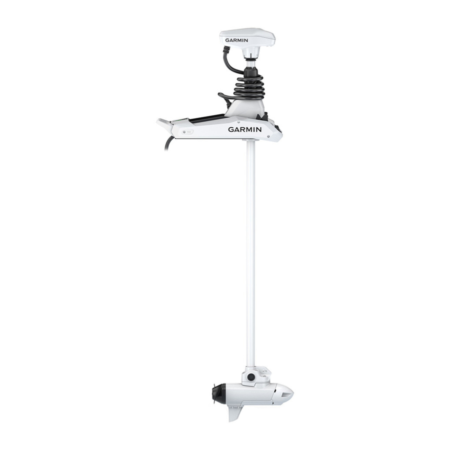
Device Overview

 | Shaft cap |
 | Power and transducer cables |
 | Depth-adjustment collar |
 | Steering system |
 | Mount |
 | Shaft |
 | Propeller drive motor |
Mounting Considerations
You must install the motor in a location where no large metallic objects, such as a tool box, are near the display panel when it is deployed. Large metallic objects can interfere with the magnetic compass, affecting the built-in autopilot performance and potentially leading to personal injury or property damage.
When selecting a mounting location, observe these considerations.
- You must install the motor on the bow of your boat.
- You should install the mount so the deployed motor is as close to the centerline of the boat
![]() as possible.
as possible.

- You must install the mount with the top of the cutout
![]() overhanging the gunwale of the boat. The U shape should extend over the side of the boat.
overhanging the gunwale of the boat. The U shape should extend over the side of the boat.

 overhanging the gunwale of the boat. The U shape should extend over the side of the boat.
 NOTE: If there is not enough room on the gunwale to install all six bolts, a minimum of four bolts must be used.
- The motor secures to the deck of the boat using bolts, so you must have room to secure the mount from the underside using washers and nuts.
- The motor must have clearance to move from the deployed to the stowed position and back again, so the installation location must be clear of obstacles.
- Verify that the deck is strong enough for the weight and force of the trolling motor. Use a backing plate or reinforce the boat if needed.
Connection Considerations
When making the wiring connections, observe the following considerations.
- You must connect the trolling motor to a 24 or 36 Vdc battery bank capable of supplying 60 A continuously.
- You must connect to the power source through a circuit breaker rated for continuous 60 A (not included).
- If necessary, you can extend the power cable using the appropriate wire gauge based on the length of the extension (Power Cable Extensions).
- For convenience, you can install a trolling motor plug and receptacle rated for 60 A or greater (not included) in the bulkhead to make it easier to disconnect the motor from the power source.
Installation Procedures
NOTICE
When assembling the motor, you must use hand tools to install all of the parts, observing the torque specifications when provided. Using power tools to assemble the motor may damage the components, and voids the warranty.
Installing the Motor on the Deck
NOTE: If the supplied bolts are not long enough for the mounting surface, you must obtain the appropriate length stainless steel pan head 5/16in. -20 (M8x1) bolts.
- Select a mounting location on the bow of your boat, according to the mounting considerations.
- Place the included mounting template on the mounting location with the mount on the template overhanging the gunwale or the edge of the boat deck.
- Mark the mounting hole locations on the boat deck.
NOTE: Use the six symmetrical holes in the mount for standard installation. The seventh hole is not needed for most installations.
- Using a 11/32 in. (9 mm) drill bit, drill the mounting holes.
- Place the motor on the boat deck, aligning the holes on the mount with the mounting holes.
- Secure the mount to the deck using the included bolts
![]() , washers
, washers ![]() , and locking nuts
, and locking nuts ![]() in the two holes closest to the gunwale or edge of the boat deck.
in the two holes closest to the gunwale or edge of the boat deck.

- Adjust the depth stop so that the motor can deploy without hitting the ground.
- Press the release
![]() , slide the propeller drive motor head out
, slide the propeller drive motor head out ![]() , and gently pivot the trolling motor into the deployed position
, and gently pivot the trolling motor into the deployed position ![]() .
.

 in the two holes closest to the gunwale or edge of the boat deck.
 , slide the propeller drive motor head out
  , and gently pivot the trolling motor into the deployed position
  .
.
Installing the Nose Cone
NOTE: Most models come fully assembled. This procedure is only required for the 90-inch Force Kraken Trolling Motor.
Using a 4 mm hex bit or wrench, secure the nose cone to the front of the propeller drive motor using the two included screws, ensuring the tab is on the bottom.

Installing the Skeg
NOTE: Most models come fully assembled. This procedure is only required for the 90-inch Force Kraken Trolling Motor.
Using a 4 mm hex bit or wrench, secure the skeg to the propeller drive motor using the four included screws, ensuring the longer end of the skeg faces the propeller side.

Installing the Propeller
- Insert the pin
![]() through the propeller motor shaft
through the propeller motor shaft ![]() .
.

 through the propeller motor shaft
  .
.
- If necessary, rotate the motor shaft to orient the pin horizontally so it is less likely to fall out during installation.
- Align the channel on the inside of the propeller
![]() with the pin, and slide the propeller onto the motor shaft.
with the pin, and slide the propeller onto the motor shaft. - Place the anode
![]() , washer
, washer ![]() , lock washer
, lock washer ![]() , and nut
, and nut ![]() onto the end of the motor shaft.
onto the end of the motor shaft. - Using a 9/16 in. (14 mm) socket, tighten the lock nut to 16.27 N-m (12 lbf-ft) to secure the propeller.
 with the pin, and slide the propeller onto the motor shaft.
 , and nut
 Connecting to Power
To avoid possible serious personal injury or property damage, the circuit breaker must be in the off position before you connect the power cables from the trolling motor.
- Route the power cable to the breaker panel or the location where you plan to install the breaker.
- If necessary, extend the power cable using the appropriate wire gauge based on the length of the extension (Power Cable Extensions) using solder and heat-shrink tubing.
- Install a trolling motor plug and receptacle rated for 60 A or greater where the power cable enters a bulkhead (optional).
- Connect the power cable to a circuit breaker rated for 60 A (continuous).
- If necessary, connect the circuit breaker to a 60 A, 24 or 36 Vdc power source. Power Cable Extensions
You must follow these requirements when extending the power cables for this product. Improperly extended power cables will cause excess electrical current, potentially leading to personal injury or property damage.
- You must use single-conductor stranded wire with insulation rated for at least 75°C (167°F) that is not bundled, not sheathed, and not run through conduit.
NOTE: If you are using wire with insulation rated for at least 105°C (221°F), and it is run outside of engine spaces, you can bundle up to three wires inside a sheath or conduit.
- When installing the extension, you must follow all industry standards and best practices.
- You must use the appropriate wire gauge based on the length of the extension.
| Extension length | Minimum wire gauge | Optimal wire gauge |
| 0 to 3 m (0 to 10 ft. ) | 6 AWG (16 mm2) | 6 AWG (16 mm2) |
| 3 to 4.6 m (10 to 20 ft.) | 6 AWG (16 mm2) | 4 AWG (25 mm2) |
| 4.6 to 9.1 m (20 to 30 ft.) | 6 AWG (16 mm2) | 2 AWG (35 mm2) |
Connecting the Transducer to a Chartplotter
Select Force Kraken Trolling Motor models include a built-in transducer. If your model does not include a transducer, you must install one before you can connect it to a compatible chartplotter. The built-in 12-pin transducer is compatible with select Garmin® chartplotter models. Go to garmin.com or contact your Garmin dealer for more information.
- Route the transducer cable to the installed chartplotter. If necessary, connect the included extension cable or a longer extension cable.
- Install the locking collar on the end of the transducer cable.
- Connect the transducer cable to the transducer port on the back of the chartplotter.
You can refer to the instructions provided with your chartplotter to identify the transducer port.
Stabilizer Installation
The stabilizer is an optional accessory that can provide additional support for the trolling motor when it is in the stowed position.
NOTE: The stabilizer is only included with the Force Kraken 90" Trolling Motor.
Installation instructions for the stabilizer are provided in the stabilizer box.
Stowing the Motor from the Deployed Position
- Hold down the pedal to release the latch


NOTE: The motor should automatically steer to 90° for stowing. The propeller stow side can be configured in the settings menu.
- Tilt the shaft back
![]() , and then raise the motor slowly while tilting the shaft to the horizontal position.
, and then raise the motor slowly while tilting the shaft to the horizontal position. - Slide the motor into the motor catch until it locks in the stowed position
![]() .
.
Push forward along the length of the shaft, and then pull backward along the length of the shaft to ensure that the motor is firmly locked in place. If the motor is not firmly locked in the stowed position, the motor may deploy unexpectedly while in rough waters or trailering, which could result in possible property damage or serious personal injury.
The depth adjustment collar must be moved as close to the base of the motor as possible. Failure to do so could cause unexpected trolling motor deployment, leading to potential property damage or serious personal injury.
- If installed, clamp the motor shaft in the stabilizer.
Remote Control Installation
The remote control connects to the trolling motor wirelessly and is paired at the factory.
Operation instructions are included in the Force Kraken Trolling Motor Quick Start Manual.
Maintenance Needs and Schedule
NOTICE
After using the motor in salt water or brackish water, you must rinse off the entire motor with fresh water, and apply a water-based silicone spray using a soft cloth. You must avoid spraying jets of water at the shaft cap, to prevent water ingress that could lead to product damage.
To maintain your warranty, you must perform a series of routine maintenance tasks as you prepare your motor for the season. If you use or transport the motor in salt water or dry, dusty environments (traveling on gravel roads, for example) you should perform these tasks more often during the season.
For detailed procedures and information on service and replacement parts, go to garmin.com/manuals/kraken _trolling_motor to download the Force Kraken Trolling Motor Maintenance Manual.

- Examine the coil cable
![]() for wear, and replace it as necessary.
for wear, and replace it as necessary. - Check and clean the power cables
![]() .
. - Lubricate the hinge with marine grade grease.
- Clean and lubricate the stow and deploy latch pedal
![]() and latch bar.
and latch bar. - Clean or replace the anodes
![]() in the propeller drive motor.
in the propeller drive motor. - Remove entangled fishing line and other obstructions from the propeller.
 for wear, and replace it as necessary.
 .
.Motor Information
Stowed Dimensions

| Item | 48 in. Model | 63 in. Model | 75 in. Model | 90 in. Model |
 overall length overall length | 156 cm (617/16 in.) | 194.1 cm (767/16 in.) | 224.8 cm (881/2 in.) | 262.68 cm (1033/8 in.) |
 mount height mount height | 26.2 cm (105/16 in.) | 26.2 cm (105/16 in.) | 26.2 cm (105/16 in.) | 26.2 cm (105/16 in.) |
 overhang height overhang height | 1.7 cm (11/16 in.) | 1.7 cm (11/16 in.) | 1.7 cm (11/16 in.) | 1.7 cm (11/16 in.) |
 minimum overhang length minimum overhang length | 20.7 cm (81/8 in.) | 20.7 cm (81/8 in.) | 20.7 cm (81/8 in.) | 20.7 cm (81/8 in.) |
 maximum length on boat maximum length on boat | 130.2 cm (515/16 in.) | 168.3 cm (661/4 in.) | 206.4 cm (811/4 in.) | 236.88 cm (931/4 in.) |
Deployed Dimensions

| Item | 48 in. Model | 63 in. Model | 75 in. Model | 90 in. Model |
 minimum height minimum height | 48.6 cm (19 1/8 in.). | 48.6 cm (19 1/8 in.). | 48.6 cm (19 1/8 in.). | 48.6 cm (19 1/8 in.). |
 mount length on deck mount length on deck | 46 cm (181/8 in.) | 46 cm (181/8 in.) | 46 cm (181/8 in.) | 46 cm (181/8 in.) |
 maximum propeller depth maximum propeller depth | 87.95 cm (34 5/8 in.) | 126 cm (49 5/8 in.) | 156.5 cm (61 5/8 in.) | 194.6 cm (76 5/8 in.) |
 maximum distance to from mount to skeg tip maximum distance to from mount to skeg tip | 107.32 cm (42 1/4 in.) | 145 cm (57 1/4 in.) | 175.9 cm (69 1/8 in.) | 213.7 cm (84 1/8 in.) |

| Item | All Models |
 mount length mount length | 61.2 cm (24 1/8 in.) |
 motor head length motor head length | With transducer: 42.7 cm(16 13/16 in.) Without transducer: 41.2 cm (16 1/4 in.) |
 mount width mount width | 24.6 cm (9 11/16 in.) |
Specifications
Trolling Motor
| Weight (motor, mount, and cables) | 48 in. white model: 22.6 kg (50 lb.) 48 in. black model: 23.2 kg (51 lb.) 63 in. white model: 24 kg (53 lb.) 63 in. black model: 24.5 kg (54 lb.) 75 in. white model: 24.5 kg (54 lb.) 75 in. black model: 25.4 kg (56 lb.) 90 in. white model: 25 kg (55 lb.) |
| Weight (stabilizer) | 0.66 kg (1.45 lb.) |
| Operating temperature | From -5° to 40°C (from 32° to 104°F) |
| Storage temperature | From -40° to 85°C (-40° to 185°F) |
| Material | Mount and motor housing: aluminum Shaft cap, display panel, and side panels: plastic Motor shaft: fiberglass |
| Water rating | Shaft cap: IEC 60529 IPX5[1] Steering motor housing: IEC 60529 IPX7[2] Display panel housing: IEC 60529 IPX72 Propeller drive motor housing: IEC 60529 IPX8[3] |
| Compass safe distance | 61 cm (2 ft.) |
| Power cable length | 1.2 m (4 ft.) |
| Input voltage | From 20 to 45 Vdc |
| Input amperage | 60 A continuous |
| Breaker (not included) | 42 VDC or greater, suitable for 60 A continuous
|
| Main power usage at 36 Vdc 60 A | Off: 72 mW Full power: 2160 W |
| Radio frequency | 2.4 GHz @ 17.4 dBm Max |
[1] The part withstands projected water exposure from any direction (such as rain).
[2] The part withstands incidental immersion in water up to 1 m deep for up to 30 min.
[3] The part withstands continuous immersion in water up to 3 m deep.
[4] Withstands incidental exposure of water up to 1 m for up to 30 min.
Remote Control
| Dimensions (W×H×D) | 152 x 52 x 32 mm (6 x 2 x 11/4 in.) |
| Weight | 109 g (3.8 oz.) without batteries |
| Material | Glass-filled nylon |
| Display type | Sunlight-visible, transflective memory-in-pixel (MIP) |
| Display resolution | R240 x 240 pixels |
| Display size (diameter) | 30.2 mm (13/16 in.) |
| Operating temperature | From -15° to 55°C (5° to 131°F) |
| Storage temperature | From -40° to 85°C (-40° to 185°F) |
| Battery type | 2 AA (not included) |
| Battery life | 240 hr., typical use |
| Radio frequency | 2.4 GHz @ 3.4 dBm nominal |
| Water rating | IEC 60529 IPX7[4] |
| Compass-safe distance | 15 cm (6 in.) |
Documents / Resources
References
![www.garmin.com]() Officiële Garmin website | Nederland
Officiële Garmin website | Nederland![www.garmin.com]() Force® Kraken Trolling Motor, Black | Garmin Support
Force® Kraken Trolling Motor, Black | Garmin Support![support.garmin.com]() Garmin | Nederland | Support
Garmin | Nederland | Support
Download manual
Here you can download full pdf version of manual, it may contain additional safety instructions, warranty information, FCC rules, etc.
Advertisement


Need help?
Do you have a question about the FORCE KRAKEN and is the answer not in the manual?
Questions and answers