Garmin FORCE Manual
- Field service manual (84 pages) ,
- User & maintenance manual (26 pages) ,
- Replacement instructions manual (22 pages)
Advertisement
- 1 Getting Started
- 2 Installation Preparation
-
3
Installation Procedures
- 3.1 Installing the Mount on the Deck
- 3.2 Installing the Steering Servo on the Lower Link of the Mount
- 3.3 Securing the Upper Gas Spring
- 3.4 Connecting the Upper Link of the Mount to the Steering Servo Housing
- 3.5 Connecting the Motor to the Display Panel
- 3.6 Installing the Handle on the Pull Cable
- 3.7 Routing the Power and Transducer Cables Through the Mount
- 3.8 Securing the Lower Gas Spring
- 3.9 Installing the Propeller
- 3.10 Connecting to Power
- 3.11 Power Cable Extensions
- 3.12 Connecting the Transducer to a Chartplotter
- 3.13 Securing the Safety Strap
- 3.14 Stabilizer Installation
- 3.15 Foot Pedal Installation
- 3.16 Remote Control Installation
- 4 Maintenance Needs and Schedule
- 5 Motor Information
- 6 Specifications
- 7 Documents / Resources
Getting Started

- See the Important Safety and Product Information guide in the product box for product warnings and other important information.
- Failure to install this device according to these instructions could result in personal injury, damage to the vessel or device, or poor product performance.
- Do not run the motor when the propeller is out of the water. Contact with the rotating propeller may result in severe injury.
- Do not use the motor in areas where you or other people in the water may come into contact with the rotating propeller, which could result in severe injury.
- Always disconnect the motor from the battery before handling or working with the propeller, propeller drive motor, electrical connections, or electronics enclosures to avoid serious injury or death.

- For the best possible performance and to avoid potential injury, damage to the device, or damage to your vessel, installation by a qualified marine installer is recommended.
- To avoid possible personal injury, always wear safety goggles, ear protection, and a dust mask when drilling, cutting, or sanding.
- When stowing or deploying the motor, be aware of the risk of entrapment or pinching from moving parts, which can result in personal injury.
- When stowing or deploying the motor, maintain stable footing and be aware of slick surfaces around the motor. Losing your footing while stowing or deploying the motor may result in injury.
- You must always secure the safety strap after stowing the trolling motor to prevent the motor from deploying unexpectedly. An unexpected deployment of the motor may lead to personal injury and damage to your boat and to the trolling motor.
 NOTICE
When drilling or cutting, always check what is on the opposite side of the surface to avoid damaging the vessel.
Tools and Supplies Needed
- Drill and a 5/16 in. (8 mm) drill bit
- #1 Phillips screwdriver
- #2 Phillips screwdriver
- 3 mm and 4 mm hex bits or wrenches (two 4 mm recommended)
- 9/16 in. (14 mm) socket
- Torque wrench
- Circuit breaker rated for continuous 60 A
- Trolling motor plug and receptacle rated for 60 A or greater (optional)
- 6, 4, or 2 AWG (16, 25, or 35 mm2) wire for extended runs of the power cable
- Solder and heat-shrink tubing, if extending the power cable
- Stainless steel pan head 1/4-20 (M6x1) bolts (if the included bolts are not long enough to mount the motor to the deck)
Installation Preparation
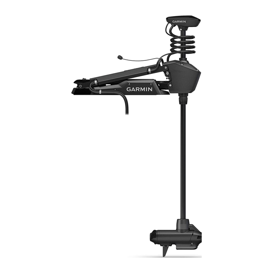
Device Overview

- Shaft cap
- Power and transducer cables
- Steering system
- Mount
- Depth-adjustment collar
- Shaft
- Propeller drive motor
Mounting Considerations
You must install the motor in a location where no large metallic objects, such as a tool box, are near the display panel when it is deployed. Large metallic objects can interfere with the magnetic compass, affecting the built-in autopilot performance and potentially leading to personal injury or property damage.
When selecting a mounting location, observe these considerations.
- You must install the motor on the bow of your boat.
- You should install the mount so the deployed motor is as close to the centerline of the boat
![]() as possible.
as possible.

- You must install the mount with the bumper
![]() overhanging the gunwale of the boat.
overhanging the gunwale of the boat. - The motor secures to the deck of the boat using bolts, so you must have room to secure the mount from the underside using washers and nuts.
- The motor must have clearance to move from the deployed to the stowed position and back again, so the installation location must be clear of obstacles.
- Verify that the deck is strong enough for the weight and force of the trolling motor. Use a backing plate or reinforce the boat if needed.
 as possible.

Parts Bags
The installation hardware for the trolling motor is included in labeled bags. As you complete the installation process, each procedure begins with a reference to the label on the parts bag needed to complete the procedure. You can use this table to review or verify the parts bags needed for the installation procedures.
 | Contains the safety strap and the hardware used to secure the mount base to the boat deck. |
 | Contains the pin needed to secure the steering system to the lower half of the mount. |
 | Contains the hardware needed to secure the upper and lower gas springs. |
 | Contains the pin needed to secure the steering system to the upper half of the mount. |
 | Contains the pull-cable handle hardware. |
 | Contains the hardware needed to secure the cables to the mount. |
Connection Considerations
When making the wiring connections, observe the following considerations.
- You must connect the trolling motor to a 24 or 36 Vdc battery bank capable of supplying 60 A continuously.
- You must connect to the power source through a circuit breaker rated for continuous 60 A (not included).
- If necessary, you can extend the power cable using the appropriate wire gauge based on the length of the extension (Power Cable Extensions).
- For convenience, you can install a trolling motor plug and receptacle rated for 60 A or greater (not included) in the bulkhead to make it easier to disconnect the motor from the power source.
Installation Procedures
NOTICE
When assembling the motor, you must use hand tools to install all of the parts, observing the torque specifications when provided. Using power tools to assemble the motor may damage the components, and voids the warranty.
Installing the Mount on the Deck
Label identifying the parts bag required for this procedure:
![]()
NOTE: If the supplied bolts are not long enough for the mounting surface, you must obtain the appropriate length stainless steel pan head 1/4-20 (M6x1) bolts.
- Select a mounting location on the bow of your boat, according to the mounting considerations.
- Pivot the top parts of the mount up and back so you can access the mounting holes on the mount base.
- Place the included mounting template on the mounting location with the mount bumper on the template
![]() overhanging the gunwale or the edge of the boat deck.
overhanging the gunwale or the edge of the boat deck.

![warning]() NOTE: There are two mounting hole options on the port side of the bow end of the base. You can choose which mounting hole to use depending on the installation angle and the shape of the hull.
NOTE: There are two mounting hole options on the port side of the bow end of the base. You can choose which mounting hole to use depending on the installation angle and the shape of the hull. - Mark the mounting hole locations on the boat deck.
- Using a 5/16 in. (8 mm) drill bit, drill the mounting holes.
- Place the safety strap
![]() under the mount base near the center, with the hook and loop fasteners facing downward.
under the mount base near the center, with the hook and loop fasteners facing downward.
![warning]() NOTE: You must place the safety strap under the mount before you secure it to the surface. If you do not install the safety strap at this time, you may need to partially disassemble the motor later to install it correctly.
NOTE: You must place the safety strap under the mount before you secure it to the surface. If you do not install the safety strap at this time, you may need to partially disassemble the motor later to install it correctly. - Place the mount base on the boat deck on top of the safety strap, aligning the holes on the mount with the mounting holes.
- Secure the mount to the deck using the included bolts
![]() , washers
, washers ![]() , and locking nuts
, and locking nuts ![]() .
. - Tighten the nuts to 10.85 N m (8 lbf-ft.).

Installing the Steering Servo on the Lower Link of the Mount
Label identifying the parts bag required for this procedure:
![]()
- Pivot the lower link of the mount forward until it locks into the base.

- Push the two safety rods
![]() into the lower link as far as possible.
into the lower link as far as possible.

- Make sure that the bushings
![]() are installed in the lower holes
are installed in the lower holes ![]() on the steering servo housing.
on the steering servo housing.
If the bushings were removed, you can re-insert them from the inside out. - Holding the pull cable
![]() up, place the steering servo housing onto the lower link of the mount, aligning the lower holes on the housing with the holes on the link.
up, place the steering servo housing onto the lower link of the mount, aligning the lower holes on the housing with the holes on the link.

- While lifting up on the steering servo housing, push the pivot pin
![]() through the housing and the link to hold it in place.
through the housing and the link to hold it in place.
![warning]() NOTICE
NOTICE
Do not hit the pin with a hammer or other object. Do not drill or modify the holes. Although it is a snug fit, the pin slides in completely when pushed by hand. Damage caused by hammering the pin or modifying the holes is not covered under warranty. - Route the pull cable upward through the top of the steering servo housing
![]() .
.


 into the lower link as far as possible.
 are installed in the lower holes
  on the steering servo housing.
 .
.
Securing the Upper Gas Spring
Label identifying the parts bag required for this procedure:
![]()
- Push the safety rod
![]() toward the steering servo housing as far as possible to lock the lower pivot pin in place.
toward the steering servo housing as far as possible to lock the lower pivot pin in place.

- If necessary, pivot the upper gas spring toward the lower link of the mount so the base of the gas spring aligns with the safety rod and mounting holes.
![]()
If you must rotate the gas spring so the base aligns with the mount, rotate the spring in a clockwise direction only. Rotating the gas spring in a counter-clockwise direction may loosen the fittings, potentially leading to a premature failure of the gas spring, which could lead to personal injury or property damage while stowing or deploying the motor. - Align the single hole on the base of the gas spring
![]() with the safety rod, and press down.
with the safety rod, and press down.
The screw holes on the base![]() should align with the holes on the bottom of the mount.
should align with the holes on the bottom of the mount. - Using a #2 Phillips screwdriver, secure the base of the gas spring to the lower link of the mount using the included screws
![]() .
.

Keep the remaining screws in the parts bag. You must use them when securing the other gas spring in a later procedure.
Connecting the Upper Link of the Mount to the Steering Servo Housing
Label identifying the parts bag required for this procedure:
![]()
- Remove the tape that secures the data cable
![]() to the steering servo housing.
to the steering servo housing. - Make sure that the bushings
![]() are installed in the upper holes on the steering servo housing.
are installed in the upper holes on the steering servo housing.

If the bushings were removed, you can re-insert them from the outside in. - Pivot the upper link of the mount forward.
![]()
- Tip the top of the steering servo housing inward so the holes on the upper link and the housing align.
- Push the pin
![]() through the holes on the upper link of the mount and the steering servo housing.
through the holes on the upper link of the mount and the steering servo housing.

- Using a 4 mm hex bit or hex wrench, secure the pin using the screws and washers
![]() on both sides.
on both sides.

![warning]() NOTE: To properly secure the pin, you should use two hex bits or wrenches so the pin does not rotate as you tighten the screws.
NOTE: To properly secure the pin, you should use two hex bits or wrenches so the pin does not rotate as you tighten the screws.


Connecting the Motor to the Display Panel
NOTICE
You must connect the cable from the steering servo to the display panel before proceeding further with the installation. If you do not make this connection now, the unsecured cable may damage the display panel when moving the mount.
- Route the cable
![]() from the steering servo housing to the display panel
from the steering servo housing to the display panel ![]() on the upper link of the mount.
on the upper link of the mount.

- Push the connector onto the port on the display panel, and rotate the locking ring clockwise to secure it.
 from the steering servo housing to the display panel
  on the upper link of the mount.
NOTE: The connector is keyed to fit into the port one way only, and will fit easily when aligned correctly. Do not force the connector into the port.
Installing the Handle on the Pull Cable
Label identifying the parts bag required for this procedure:
![]()
- Insert the pull cable
![]() through the bottom half of the handle
through the bottom half of the handle ![]() .
.

- Insert the pull cable through the washer
![]() .
. - Push the R-pin
![]() through the hole on the end of the pull cable.
through the hole on the end of the pull cable. - Pull the cable down so that the washer and R-pin rest in the bottom half of the handle.
![warning]() NOTE: The R-pin fits in the bottom half of the handle one way only.
NOTE: The R-pin fits in the bottom half of the handle one way only. - Using a #1 Philips screwdriver, secure the top of the handle
![]() to the bottom using the screws
to the bottom using the screws ![]() .
.


Routing the Power and Transducer Cables Through the Mount
Label identifying the parts bag required for this procedure:
![]()
NOTICE
To avoid damaging the power and transducer cables when deploying and stowing the trolling motor and to avoid interference with the GPS and heading sensors in the motor, you must route the cables through the right (starboard) side of the mount and secure them using the included hardware. You must not route the power cable through the left (port) side of the mount, and it is not possible to install the included brackets on the left (port) side. The left (port) side is reserved for additional accessories or transducer cables that you may install in the future.
- Measure approximately 40 cm (16 in.) on the power cable from where it connects to the steering servo housing, and look for the mark on the cable applied at the factory.

- If you do not see a mark on the cable, or if the mark is not approximately 40 cm (16 in.) from the connection, make a mark with a marker or tape.
- With the motor in the deployed position, route the transducer cable through the channel along the right (starboard) side of the mount
![]() .
.

![information]() TIP: To determine the right (starboard) side of the mount, stand in a location where you can read the information on the display panel.
TIP: To determine the right (starboard) side of the mount, stand in a location where you can read the information on the display panel.


 TIP: To determine the right (starboard) side of the mount, stand in a location where you can read the information on the display panel.
- Route the power cable through the channel above the transducer cable.
- Using the pull cable, carefully lift the motor from the deployed position to the stowed position.
![]()
Because only one of the lift-assist gas springs is secured at this point in the installation, you must use caution when lifting the motor to the stowed position. The weight of the motor may cause the mount to move quickly and pinch or crush hands or fingers.
![warning]() NOTICE
NOTICE
You must secure the cables to the mount with the motor in the stowed position. If you complete this procedure with the motor in the deployed position, the cables are not at their fully extended length, and the added stress may damage the cables during use. - Leaving a rounded bend in the cables
![]() , hold them against the side of the mount where they enter the channel.
, hold them against the side of the mount where they enter the channel.

- At the marked location on the power cable, place one of the brackets that has two screw holes
![]() over the cables and against the mount, aligning the holes on the bracket with the holes on the mount.
over the cables and against the mount, aligning the holes on the bracket with the holes on the mount. - Using a 3 mm hex bit or wrench, secure the bracket to the mount using two screws
![]() .
. - Hold the cables against the bottom of the mount where they exit the channel.
- Place the other bracket that has two screw holes
![]() over the cables and against the mount, aligning the holes on the bracket with the holes on the mount.
over the cables and against the mount, aligning the holes on the bracket with the holes on the mount.

- Using a 3 mm hex bit or wrench, secure the bracket to the mount using two screws
![]() .
. - Hold the cables against the plastic portion of the mount base, close to the boat deck.
- Insert the lower tab on the remaining bracket into a slot below the cables
![]() , and rotate the bracket toward the mount base to hold the cables.
, and rotate the bracket toward the mount base to hold the cables.

- Using a #1 Phillips screwdriver, secure the upper tab of the bracket to the mount base using a single screw
![]() .
. - Install additional plastic cable clips to secure the transducer cable to the power cable where needed (optional).
Two plastic cable clips are included in the parts bag.
 , hold them against the side of the mount where they enter the channel.

 .
.
Securing the Lower Gas Spring
Label identifying the parts bag required for this procedure:
![]()
NOTE: This procedure uses the rest of the hardware in the parts bag that you used when installing the upper gas spring.
- If necessary, transition the trolling motor from the deployed to the stowed position. If the gas spring is positioned on the other side of the mount after you stowed the motor, you may need to lift up the mount and flip over the gas spring so you can secure it to the mount.
- Align the hole on the base of the lower gas spring
![]() with the safety rod
with the safety rod ![]() , and press down.
, and press down.

![]()
If you must rotate the gas spring so the base aligns with the mount, rotate the spring in a clockwise direction only. Rotating the gas spring in a counter-clockwise direction may loosen the fittings, potentially leading to a premature failure of the gas spring, which could lead to personal injury or property damage while stowing or deploying the motor. - Using a #2 Phillips screwdriver, secure the base of the lower gas spring to the mount using the included screws
![]() .
.

 .
.Installing the Propeller
The parts bag containing the hardware needed for this procedure is included in the box with the propeller and does not have a label.
- Insert the pin
![]() through the propeller motor shaft
through the propeller motor shaft ![]() .
.

- If necessary, rotate the motor shaft to orient the pin horizontally so it is less likely to fall out during installation.
- Align the channel on the inside of the propeller
![]() with the pin, and slide the propeller onto the motor shaft.
with the pin, and slide the propeller onto the motor shaft. - Place the anode
![]() , washer
, washer ![]() , lock washer
, lock washer ![]() , and nut
, and nut ![]() onto the end of the motor shaft.
onto the end of the motor shaft. - Using a 9/16 in. (14 mm) socket, tighten the lock nut to 16.27 N-m (12 lbf-ft) to secure the propeller.

 , and nut
 Connecting to Power
To avoid possible serious personal injury or property damage, the circuit breaker must be in the off position before you connect the power cables from the trolling motor.
- Route the power cable to the breaker panel or the location where you plan to install the breaker.
- If necessary, extend the power cable using the appropriate wire gauge based on the length of the extension (Power Cable Extensions using solder and heat-shrink tubing.
- Install a trolling motor plug and receptacle rated for 60 A or greater where the power cable enters a bulkhead (optional).
- Connect the power cable to a circuit breaker rated for 60 A (continuous).
- If necessary, connect the circuit breaker to a 60 A, 24 or 36 Vdc power source.
Power Cable Extensions
You must follow these requirements when extending the power cables for this product. Improperly extended power cables will cause excess electrical current, potentially leading to personal injury or property damage.
- You must use single-conductor stranded wire with insulation rated for at least 75°C (167°F) that is not bundled, not sheathed, and not run through conduit.
![warning]() NOTE: If you are using wire with insulation rated for at least 105°C (221°F), and it is run outside of engine spaces, you can bundle up to three wires inside a sheath or conduit.
NOTE: If you are using wire with insulation rated for at least 105°C (221°F), and it is run outside of engine spaces, you can bundle up to three wires inside a sheath or conduit. - When installing the extension, you must follow all industry standards and best practices.
- You must use the appropriate wire gauge based on the length of the extension.
| Extension length | Minimum wire gauge | Optimal wire gauge |
| 0 to 3 m (0 to 10 ft. ) | 6 AWG (16 mm2) | 6 AWG (16 mm2) |
| 3 to 4.6 m (10 to 20 ft.) | 6 AWG (16 mm2) | 4 AWG (25 mm2) |
| 4.6 to 9.1 m (20 to 30 ft.) | 6 AWG (16 mm2) | 2 AWG (35 mm2) |
Connecting the Transducer to a Chartplotter
- Route the transducer cable to the installed chartplotter. If necessary, connect the included extension cable or a longer extension cable.
- Install the locking collar on the end of the transducer cable.
- Connect the transducer cable to the transducer port on the back of the chartplotter.
You can refer to the instructions provided with your chartplotter to identify the transducer port.
Securing the Safety Strap
You must always secure the safety strap after stowing the trolling motor to prevent the motor from deploying unexpectedly. An unexpected deployment of the motor may lead to personal injury and damage to your boat and to the trolling motor.
The safety strap holds the motor securely to the base in the stowed position and prevents unintended deployment.
- With the motor in the stowed position, lift the long end of the strap
![]() over the top of the motor.
over the top of the motor.

- Feed the end of the strap through the buckle
![]() on the other end of the strap.
on the other end of the strap.

- Pull the strap through the buckle until it holds the motor securely to the mount.
- Pull the strap away from the buckle, and push down to fasten it to the other side of the strap.
Stabilizer Installation
The stabilizer is an optional accessory that can provide additional support for the trolling motor when it is in the stowed position.
NOTICE
You must install the stabilizer to reduce the risk of damage to the trolling motor mount and to the vessel while driving in rough conditions or trailering.
Installation instructions for the stabilizer are provided in the stabilizer box.
Foot Pedal Installation
The foot pedal connects to the trolling motor wirelessly and is paired at the factory.
Detailed mounting and power instructions are included in the foot pedal box. Operation instructions are included in the Force Trolling Motor Quick Start Manual.
Remote Control Installation
The remote control connects to the trolling motor wirelessly and is paired at the factory.
Operation instructions are included in the Force Trolling Motor Quick Start Manual.
Maintenance Needs and Schedule
NOTICE
After using the motor in salt water or brackish water, you must rinse off the entire motor with fresh water, and apply a water-based silicone spray using a soft cloth. You must avoid spraying jets of water at the shaft cap, to prevent water ingress that could lead to product damage.
To maintain your warranty, you must perform a series of routine maintenance tasks as you prepare your motor for the season. If you use or transport the motor in dry, dusty environments (traveling on gravel roads, for example) you should perform these tasks more often during the season.
For detailed procedures and information on service and replacement parts, download the Force Trolling Motor Maintenance Manual from garmin.com/manuals/force_trolling_motor.

- Examine the power cable for wear, and patch, repair, or replace as necessary
![]() .
. - Check and clean the power terminals and tighten the nuts, if necessary
![]() .
.
 .
. .
.- Lubricate the hinges and bushings
![]() .
. - Clean and lubricate the stow and deploy latch mechanism
![]() .
. - Check the mount rails, and replace them if necessary
![]() .
. - Check the mount bumper, and replace it if necessary
![]() .
. - Clean or replace the anodes in the propeller drive motor
![]() .
. - If installed, check the rubber stops on the ends of the stabilizer
![]() for wear and replace them as necessary.
for wear and replace them as necessary.
 .
. .
. .
. .
. for wear and replace them as necessary.
Motor Information
Stowed Dimensions

| Item | 50 in. Model | 57 in. Model |
 | 1.558 m (615/16 in.) min. 1.811 m (715/16 in.) max. | 1.712 m (673/8 in.) min. 2.066 m (815/16 in.) max. |
 | 300 mm (1113/16 in.) | 340 mm (133/8 in.) |
Deployed Dimensions

| Item | 50 in. Model | 57 in. Model |
 | 461 mm (18 1/8 in.) min. 721 mm (28 3/8 in.) max. | 488 mm (19 3/16 in.) min. 817 mm (32 1/8 in.) max. |
 | 708 mm (27 7/8 in.) | 799 mm (31 7/16 in.) |
 | 648 mm (25 1/2 in.) min. 889 mm (35 in.) max. | 737 mm (29 in.) min. 1.07 m (42 in.) max. |
 | 839 mm (33 1/16 in.) min. 1.1 m (43 5/16 in.) max. | 920 mm (36 3/16 in.) min. 1.18 m (46 1/2 in.) max. |

| Item | 50 in. Model | 57 in. Model |
 | 931 mm (36 11/16 in.) | 1.022 m (40 1/4 in.) |
 | 402 mm (15 13/16 in.) | 402 mm (15 13/16 in.) |
 | 203 mm (8 in.) | 203 mm (8 in.) |
Specifications
Trolling Motor
| Weight (motor, mount, and cables) | 50 in. model: 30 kg (66 lb.) 57 in. model: 31.75 kg (70 lb.) |
| Weight (stabilizer) | 0.54 kg (1.2 lb.) |
| Operating temperature | From -5° to 40°C (from 32° to 104°F) |
| Storage temperature | From -40° to 85°C (-40° to 185°F) |
| Material | Mount and motor housing: aluminum Shaft cap, display panel, and side panels: plastic Motor shaft: fiberglass |
| Water rating | Shaft cap: IEC 60529 IPX5[1] Steering motor housing: IEC 60529 IPX7[2] Display panel housing: IEC 60529 IPX7 Propeller drive motor housing: IEC 60529 IPX8[3] |
| Compass safe distance | 91 cm (3 ft.) |
| Power cable length | 50 in. model: 1.2 m (4 ft.) 57 in. model: 1.1 m (3.5 ft.) |
| Input voltage | From 20 to 45 Vdc |
| Input amperage | 60 A continuous |
| Breaker (not included) | 42 VDC or greater, suitable for 60 A continuous
|
| Main power usage at 36 Vdc 60 A | Off: 72 mW Full power: 2160 W |
| Radio frequency | 2.4 GHz @ 28 dBm nominal |
1 The part withstands projected water exposure from any direction (such as rain).
2 The part withstands incidental immersion in water up to 1 m deep for up to 30 min.
3 The part withstands continuous immersion in water up to 3 m deep.
Remote Control
| Dimensions (W×H×D) | 152 x 52 x 32 mm (6 x 2 x 11/4 in.) |
| Weight | 109 g (3.8 oz.) without batteries |
| Material | Glass-filled nylon |
| Display type | Sunlight-visible, transflective memory-in-pixel (MIP) |
| Display resolution | R240 x 240 pixels |
| Display size (diameter) | 30.2 mm (13/16 in.) |
| Operating temperature | From -15° to 55°C (5° to 131°F) |
| Storage temperature | From -40° to 85°C (-40° to 185°F) |
| Battery type | 2 AA (not included) |
| Battery life | 240 hr., typical use |
| Radio frequency | 2.4 GHz @ 10.0 dBm nominal |
| Water rating | IEC 60529 IPX7[4] |
| Compass-safe distance | 15 cm (6 in.) |
4 Withstands incidental exposure of water up to 1 m for up to 30 min.
Documents / Resources
References
Download manual
Here you can download full pdf version of manual, it may contain additional safety instructions, warranty information, FCC rules, etc.
Advertisement


Need help?
Do you have a question about the FORCE and is the answer not in the manual?
Questions and answers