Table of Contents
Advertisement
Quick Links
Advertisement
Table of Contents

Related Manuals for Fluidwell F113-P-PD-OS


Summary of Contents for Fluidwell F113-P-PD-OS
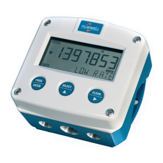
- Page 1 F113-P-PD-OS FLOW RATE MONITOR / TOTALIZER with high / low alarms, analog and pulse outputs ADDENDUM / INSTALLATION GUIDE FOR TYPE PD-OS: - 4 MECHANICAL RELAY OUTPUTS F-Series - Field mounted indicators for safe and hazardous areas. More info: www.fluidwell.com/fseries.
-
Page 2: Safety Instructions
Page 2 SAFETY INSTRUCTIONS ▪ Any responsibility is lapsed if the instructions and procedures as described in this manual are not followed. ▪ LIFE SUPPORT APPLICATIONS: The F113-P is not designed for use in life support appliances, devices, or systems where malfunction of the product can reasonably be expected to result in a personal injury. -
Page 3: About The Manual
ABOUT THE MANUAL This manual is an addendum to the standard user manual ‘FW_F113-P_vxxxx_xx_EN’ that is also supplied with the F113-P-PD-OS flow rate monitor / totalizer. This addendum describes the terminal connections and configurations that are specific for type PD-OS (4 mechanical relay outputs) and replaces chapter 4 of the standard user manual. -
Page 4: Table Of Contents
Page 4 CONTENTS MANUAL Safety instructions ..........................2 Disposal of electronic waste ....................... 2 Safety rules and precautionary measures ..................2 About the manual ..........................3 Warranty and technical support ......................3 Contents manual ..........................3 Installation ..........................5 4.1. General directions ..................... -
Page 5: Installation
Page 5 INSTALLATION 4.1. General directions • Mounting, electrical installation, start-up and maintenance of this device may only be carried out by trained persons authorized by the operator of the facility. Persons must read and understand this manual before carrying out its instructions. •... -
Page 6: Dimensions- Enclosure
Page 6 4.3. DIMENSIONS- ENCLOSURE Aluminum and stainless enclosures (where “H” turns to “HS” for stainless, e.g. HA → HSA): 75 mm (2.95") 112 mm (4.40") 130 mm (5.12") 12mm 12mm 30mm 30mm 24mm 24mm M20 x 1,5 6 x M12 36mm 36mm 25mm... - Page 7 Page 7 75 mm (2.95") 112 mm (4.40") 130 mm (5.12") HK back box: (flat bottom) 75 mm (2.95") 118 mm (4.65”) 25mm 25mm D=20mm D=20mm 12mm 12mm 30mm 30mm 24mm 24mm D=12mm D=16mm D=16mm D=20mm 36mm 36mm 0.12” 0.12” D=22mm (0.866") 3x D=22mm (0.866”) 29.1 mm (1.15”)
-
Page 8: Installing The Hardware
The wire screens shall be terminated at one side to prevent wire loops. Inside of the Fluidwell unit, the different common ground terminals are connected to each other. It is advised, as illustrated, to terminate the wire screens in the vicinity of the sensor and to insulated the wire screen with a shrink tube at the Fluidwell unit side. -
Page 9: Protective Earth (Pe) Connections
Page 9 4.4.2. PROTECTIVE EARTH (PE) CONNECTIONS Inside the unit, different types of bonding and earthing are used. The common ground is mostly used for termination of the wire shields; the Protective Earth (PE) is used for electrical safety. For externally powered installations, route the Protective Earth (PE) grounding conductor into the enclosure together with the incoming power conductors. -
Page 10: Sensor Supply
Page 10 4.4.3. SENSOR SUPPLY Option PD: Sensor supply: 3.2V, 8.2V, 12V or 24 V: With this option, a real power supply for the sensor is available. The sensor can be powered with 8.2, 12 or 24 V DC (max. 50mA@24V). The voltage is selected by the three switches inside the enclosure. - Page 11 Page 11 Terminal 03-05; Flowmeter input: Three basic types of flowmeter signals can be connected to the unit: pulse, active pulse or coil. The screen of the signal wire must be connected to the common ground terminal 03 (unless earthed at the sensor itself).
- Page 12 Page 12 For a signal detection level of 50% of the supply voltage: please refer to "active signals". PNP signal input INTERNAL EXTERNAL +3.2V DC (option: 8.1V - 12V - 24V) SIGNAL low-pass filter selection PNP-LP 100K shielding Common ground unit Active signals 8.1V - 12V and 24V: If a sensor gives an active signal, please read par.
- Page 13 Page 13 Namur signal input INTERNAL EXTERNAL (Option: PD-PN: +8.1V) +8.1V DC Namur SIGNAL 820 Ohm shielding Common ground unit Type IB - Terminal 06-07; external reset: With this function the total can be reset to zero with an external switch. The Total resets only when the switch opens.
- Page 14 Page 14 Terminal 16-17; relay output R4: This output is an alarm or pulse output according setup 84. Mechanic relay output - R1, R2, R3, R4 INTERNAL EXTERNAL maximum DEVICE 240V AC - 0.5A maximum DEVICE 240V AC - 0.5A maximum DEVICE 240V AC - 0.5A...
- Page 15 Page 15 FW_F113POS_v1901_02_EN (addendum).docx...
- Page 16 Page 16 Fluidwell B.V. FW_F113POS_v1901_02_EN (addendum).docx PO box 6 Voltaweg 23 Website: www.fluidwell.com 5460 AA Veghel 5466 AZ Veghel Find your nearest representative: www.fluidwell.com/representatives The Netherlands The Netherlands © 2017 Fluidwell B.V. - FW_F113POS_v1901_02_EN (addendum).docx...
Need help?
Do you have a question about the F113-P-PD-OS and is the answer not in the manual?
Questions and answers