ORiNG IGS-P9164 Series Quick Installation Manual
Iec 61850-3 industrial managed ethernet switch
Hide thumbs
Also See for IGS-P9164 Series:
- User manual (171 pages) ,
- Quick installation manual (2 pages)
Table of Contents
Advertisement
Quick Links
SWITCH
I N D U S T R I A L
Q
I
uick
nstallation
M A N A G E D
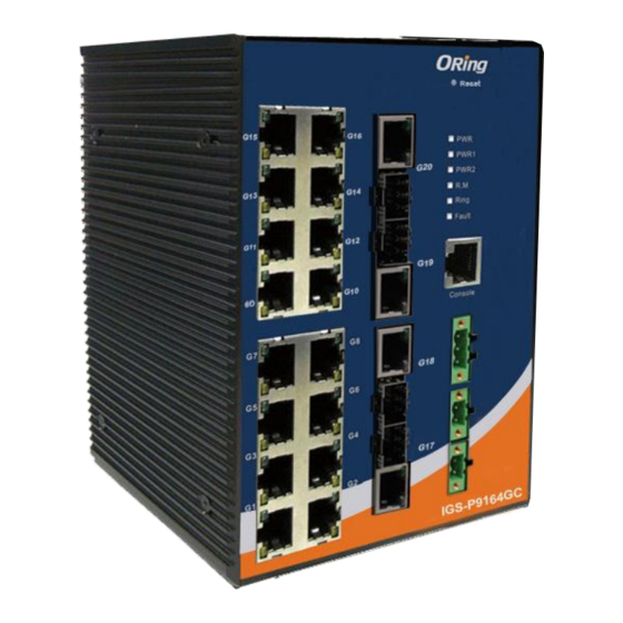
Introduction
IGS-P9164 series
are IEC 61850-3 managed redundant ring Ethernet
switches. These switches are designed for power substation application and
rolling stock application, fully compliant with the requirement of IEC 61850-3
and IEEE 1613.
are IEC 61850-3 managed redundant
IGS-P9164GF series
ring Ethernet switch with 16x10/100/1000Base-T(X) ports and 4x1000Base-X
optical fiber port with SC connector.
IGS-P9164FX series
managed redundant ring Ethernet switch with 16x10/100/1000Base-T(X)
ports and 4x100Base-FX optical fiber port with SC connector. IGS-P9164GC
series are IEC 61850-3 managed redundant ring Ethernet switch with
16x10/100/1000Base-T(X) ports and 4xGigabit combo ports with SFP socket.
With completely support of Ethernet Redundancy protocol, O-Ring (recovery
time < 30ms over 250 units of connection) and MSTP (RSTP/STP compatible)
can protect your mission-critical applications from network interruptions or
temporary malfunctions with its fast recovery technology. And support wide
o
o
operating temperature from -40 C to 85 C.
be managed centralized and convenient by Open-Vision, Except the Web-
based interface, Telnet and console (CLI) configuration.
switch is one of the most reliable choice for highly-managed and Fiber
Ethernet application.
Package Contents
The device is shipped with the following items. If any of these items is missing
or damaged, please contact your customer service representative for
assistance.
Contents
Pictures
Number
IGS-P9164GF
or IGS-P9164FX
or IGS-P9164GC
CD
DIN-rail Kit
Wall-mount Kit
Console Cable
QIG
Power Cable
(For -HV model only)
Preparation
Before you begin installing the device, make sure you have all of the package
contents available and a PC with Microsoft Internet Explorer 6.0 or later, for
using web-based system management tools.
Safety & Warnings
Elevated Operating Ambient: If installed in a closed environment, make sure
the operating ambient temperature is compatible with the maximum
ambient temperature (Tma) specified by the manufacturer.
Q I G
IGS-P9164 Series
IGS-P9164 Series
G
uide
Reduced Air Flow: Make sure the amount of air flow required for safe operation of the
equipment is not compromised during installation.
Mechanical Loading: Make sure the mounting of the equipment is not in a hazardous
condition due to uneven mechanical loading.
Circuit Overloading: Consideration should be given to the connection of the equipment to the
are IEC 61850-3
supply circuit and the effect that overloading of the circuits might have on overcurrent
protection and supply wiring. Appropriate consideration of equipment nameplate ratings
should be used when addressing this concern.
Dimension
115.0
G16
G15
Fail
G16
Close
PWR
PWR1
G20
PWR2
G14
G13
Fail
G14
Open
G12
G11
Relay
G12
G19
G10
G9
V+/L
G10
IGS-P9164GF(X) series
can also
V-/N
G8
G7
G18
PWR2
G6
G5
V+/L
G4
G3
V-/N
Therefore, the
G17
G2
G1
IGS-P9164GC-HV
PWR1
10/100/1000T
G16
G15
TX
Fail
G16
PWR
Close
G20
(P20)
PWR1
RX
G14
G13
PWR2
G14
Fail
LNK
Open
/ACT
G12
G11
TX
Relay
G12
G19
(P19)
RX
V+/L
G10
G9
G10
V-/N
G8
G7
TX
G18
(P18)
PWR2
RX
G6
G5
LNK
/ACT
V+/L
G4
G3
TX
V-/N
G17
(P17)
RX
G2
G1
10/100/1000T
1000X
IGS-P9164GF(X)-HV
PWR1
Panel Layouts
X 1
15
G16
G15
3
G20
G14
G13
1
4
2
G12
G11
G19
5
G10
G9
X 1
G8
G7
G18
G6
G5
G4
G3
X 1
G17
G2
G1
IGS-P9164GC-HV
10/100/1000T
X 2
15
G16
G15
TX
G20
3
(P20)
RX
G14
G13
4
LNK
/ACT
1
X 1
G12
G11
TX
2
G19
(P19)
RX
5
G10
G9
G8
G7
TX
X 1
G18
(P18)
G6
G5
RX
LNK
/ACT
G4
G3
TX
G17
(P17)
G2
G1
RX
X 2
1000X
IGS-P9164GF(X)-HV
10/100/1000T
Rear View
1
1
1907-2-29-IGSP9164-1.1
Unit =mm (Tolerance ±0.5mm)
G15
PWR
PWR1
G20
PWR2
G13
G11
G19
G9
Relay
COM
G8
G7
Fail Close
Fail Open
G18
G6
G5
V2-
PWR2
V2+
G4
G3
G17
V1-
G2
G1
PWR1
159.0
V1+
IGS-P9164GC-LV
10/100/1000T
40.0
G15
TX
88.0
G20
PWR
(P20)
PWR1
RX
G13
PWR2
LNK
/ACT
G11
TX
G19
(P19)
RX
G9
Relay
COM
G8
G7
Fail Close
TX
Fail Open
G18
(P18)
RX
G6
G5
LNK
/ACT
V2-
PWR2
V2+
G4
G3
TX
G17
(P17)
RX
V1-
G2
G1
PWR1
V1+
10/100/1000T
1000X
IGS-P9164GF(X)-LV
Front View
1. LNK/ACT port for Ethernet ports
15
2. 10/100/100Base-T(X) Ethernet ports
Fail
G16
G15
3
6
Close
6
PWR
PWR
12
7
PWR1
7 7
PWR1
3. Fiber ports (IGS-P9164GF/FX) or
G20
PWR2
PWR2
8
8
Fail
G14
G13
9
9
Open
Combo ports (IGS-P9164GC)
10
10
1
11
11
4
Relay
2
G12
G11
4. LNK status LED for fiber/combo ports
5
G19
5. Console port
V+/L
G10
G9
V-/N
13
Relay
6. Power LED
12
COM
G8
G7
Fail Close
7. PWR1 LED
Fail Open
G18
PWR2
8. PWR2 LED
G6
G5
13
V+/L
V2-
PWR2
9. R.M status LED
V2+
G4
G3
V-/N
14
G17
10. Ring status LED
14
V1-
PWR1
G2
G1
V1+
11. Fault indicator
PWR1
IGS-P9164GC-LV
10/100/1000T
12. Relay output
13. Power 2 module
14. Power 1 module
15
Fail
G16
G15
TX
PWR
6
Close
PWR
6
15. Reset button
G20
(P20)
3
PWR1
12
PWR1
7
7 7
RX
PWR2
PWR2
8
8
G14
G13
Fail
9
Open
9
4
LNK
/ACT
10
10
1
11
11
Relay
G12
G11
TX
2
G19
5
(P19)
RX
V+/L
G10
G9
V-/N
13
Relay
12
COM
G8
G7
Fail Close
TX
G18
Fail Open
(P18)
PWR2
G6
G5
RX
13
LNK
V2-
V+/L
/ACT
PWR2
V2+
G4
G3
V-/N
TX
14
G17
(P17)
14
V1-
G2
G1
RX
PWR1
V1+
PWR1
1000X
IGS-P9164GF(X)-LV
10/100/1000T
1. Wall-mount screw holes
2. Din-rail screw holes
2
PRINTED ON RECYCLED PAPER
IEC 61850-3 Industrial Managed Ethernet
Switch
Installation
Use the mounting kits attached with the package and follow the steps below to install the switch
to a rail or to the wall.
DIN-rail Installation
Step 1: Slant the switch and screw the Din-rail kit onto the back of the switch, right in the
middle of the back panel.
Step 2: Slide the switch onto a DIN-rail from the Din-rail kit and make sure the switch clicks into
the rail firmly.
49.67
Ø5.0
Ø4.0
Ø8.0
Wall-mounting
Step 1: Screw the two pieces of wall-mount kits onto both ends of the rear panel of the switch. A
87.9
total of six screws are required, as shown below.
Step 2: Use the switch, with wall mount plates attached, as a guide to mark the correct
locations of the four screws.
Step 3: Insert a screw head through the large parts of the keyhole-shaped apertures, and then
slide the switch downwards. Tighten the screw for added stability.
Network Connection
The switch provides standard Ethernet ports. According to the link type, the switch uses
CAT 3, 4, 5, 5e UTP cables to connect to any other network devices (PCs, servers, switches,
routers, or hubs). Please refer to the following table for cable specifications.
Cable Types and Specifications:
Cable
Type
10BASE-T
Cat. 3, 4, 5 100-ohm
100BASE-TX
Cat. 5 100-ohm UTP
1000BASE-T
Cat. 5 / Cat. 5e 100-ohm UTP
Version 1.1
G16
G15
TX
Fail
Close
G20
PWR
(P20)
PWR1
RX
PWR2
G14
G13
Fail
Open
LNK
/ACT
G12
G11
TX
Relay
G19
(P19)
RX
V+/L
G10
G9
V-/N
G8
G7
TX
G18
(P18)
PWR2
G6
G5
RX
LNK
/ACT
V+/L
G4
G3
TX
V-/N
G17
(P17)
RX
G2
G1
1000X
IGS-P9164GF(X)-HV
PWR1
10/100/1000T
Max. Length
Connector
UTP 100 m (328 ft)
RJ-45
UTP 100 m (328 ft)
RJ-45
UTP 100 m (328 ft)
RJ-45
Quick Installation Guide
Advertisement
Table of Contents

Related Manuals for ORiNG IGS-P9164 Series


Summary of Contents for ORiNG IGS-P9164 Series
- Page 1 Version 1.1 IEC 61850-3 Industrial Managed Ethernet SWITCH IGS-P9164 Series I N D U S T R I A L Switch uick nstallation uide M A N A G E D Introduction Installation Reduced Air Flow: Make sure the amount of air flow required for safe operation of the...
- Page 2 Overload current protection Present information. manual. For information on operating the switch Reverse polarity protection Present Physical Characteristic using ORing’s Open-Vision management utility, RS-232 with DB9 (female) pin PC (male) pin assignment RJ45 pin assignment please go to ORing website. Enclosure IP-30...
Need help?
Do you have a question about the IGS-P9164 Series and is the answer not in the manual?
Questions and answers