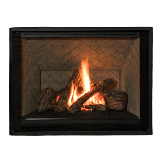
Valor H6 Series Installation Instructions Manual
Gas conversion kit for h6
Hide thumbs
Also See for H6 Series:
- Installation manual (102 pages) ,
- Installation and owner's manual (80 pages) ,
- Installation instructions manual (8 pages)
Advertisement
Available languages
Available languages
Quick Links
INSTALLATION INSTRUCTIONS
Gas Conversion Kit for H6
1400KNGK / 1400KPGK
Use with Valor Model 1400K Heaters ONLY
This appliance is certifi ed for use from 0–4500 feet. For
altitudes above 4500 feet, see local codes.
Kit Contents
1 Pilot injector
1 Gas orifi ce
1 Set of conversion labels
1 Minimum rate by-pass screw
Tools Required
• Wrenches, to disconnect gas line
• Phillips (+) screwdriver, to remove burner module
• Small (jewelers size) fl at blade screwdriver, to set
pressure
• Small fl at blade screwdriver, to release pressure tap
on valve
• Needle nose pliers, to remove by-pass screw
• Hex (Allen) wrench, 4 mm or 5/32", to remove pilot
injector
• Manometer, to set pressure when regulator is integral
with valve
Specifi cations
Model
Gas
Altitude (Ft.)*
Input Maximum (Btu/h)
Input Minimum (Btu/h)
Manifold Pressure (in w.c.)
Minimum Supply Pressure (in w.c.)
Maximum Supply Pressure (in w.c.)
Main Burner Injector Marking
Pilot Injector Marking
Min. Rate By-Pass Screw
4007154-01
©2018, Miles Industries Ltd.
H6 Series
1400KN 1400KP
Natural
Propane
0-4,500 feet*
36,000
36,000
19,000
15,000
4.0"
9.5"
5.0"
11.0
10.0"
14.0
DMS#32
DMS#49
51
30
220
125
WARNING
This conversion kit shall be installed by
a qualifi ed service agency in accordance
with the manufacturer's instructions and
all applicable codes and requirements of
the authority having jurisdiction. If the
information in these instructions is not
followed exactly, a fi re, explosion or pro-
duction of carbon monoxide may result
causing property damage, personal injury
or loss of life. The qualifi ed service agency
is responsible for the proper installation of
this kit. The installation is not proper and
complete until the operation of the con-
verted appliance is checked as specifi ed in
the manufacturer's instructions supplied
with the kit.
Use this manual in conjunction with the
installation manual supplied with the
appliance.
Advertisement

Summary of Contents for Valor H6 Series
- Page 1 INSTALLATION INSTRUCTIONS H6 Series Gas Conversion Kit for H6 1400KNGK / 1400KPGK Use with Valor Model 1400K Heaters ONLY This appliance is certifi ed for use from 0–4500 feet. For WARNING altitudes above 4500 feet, see local codes. This conversion kit shall be installed by Kit Contents a qualifi...
-
Page 2: Natural Gas
General Notes Regarding Conversion 3. Withdraw module from fi rebox. It may be necessary to break the gasket seal using a screwdriver. The conversion may be done before or after the 4. Remove pipe assembly from injector block. appliance is installed into the cavity. However, the gas must be connected to set the manifold pressure. - Page 3 Convert pilot injector 4. Insert the replacement minimum rate by-pass screw and hand tighten using a screwdriver. Refer to the 1. Remove pilot shield (2 screws). Specifi cations on page 1 for proper by-pass screw. 2. Remove the pilot hood by pulling on it. Note that the number is stamped on the barrel of the screw.
- Page 4 Close in this publication. Designed and Manufactured by / for Miles Industries Ltd. 190–2255 Dollarton Highway, North Vancouver, BC, CANADA V7H 3B1 Tel. 604-984-3496 Fax 604-984-0246 www.valorfi replaces.com © Copyright Miles Industries Ltd., 2018...
-
Page 5: Directives D'installation
FOYER À GAZ RADIANT Trousse de conversion de gaz pour H6 1400KNGK / 1400KPGK Utilisez avec les foyers Valor 1400K SEULEMENT Cet appareil est homologué pour utilisation de 0 à 4 AVERTISSEMENT 500 pieds. Pour altitudes au-dessus de 4 500 pieds, consultez la règlementation locale. - Page 6 À propos de la conversion Remplacez l’injecteur du brûleur La conversion d’un gaz à l’autre peut être faite avant 1. Utilisez deux clés pour débrancher la conduite ou après l’installation de l’appareil dans la cavité. de gaz reliée à la soupape. Cependant, le gaz doit être branché...
- Page 7 7. Réinstallez le réceptacle du brûleur. Dépendamment 3. Repérez et enlevez la vis d’indice minimum de la du type de gaz utilisé, le butoir doit être en position soupape et jetez-la. La vis est maintenue par un inversé—voir les images ci-dessous. joint torique de caoutchouc.
- Page 8 Réglez et vérifi ez la pression d’admission 2. Dévissez l’écrou à oreilles - ne l’enlevez pas! 3. Réglez le levier vers la droite ou la gauche à la 1. Fixez un manomètre à la connexion de vérifi ca- position désirée. tion de pression d’admission sur la soupape—voir l’image ci-dessous.


Need help?
Do you have a question about the H6 Series and is the answer not in the manual?
Questions and answers