Table of Contents
Advertisement
Quick Links
SIMATIC
Network components
SIMATIC BusAdapter
Operating Instructions
06/2018
C79000-G8976-C472-01
___________________
Introduction
___________________
Safety notes
___________________
Description of the device
___________________
Mounting
___________________
Connection
___________________
Maintenance and
troubleshooting
___________________
Technical data
___________________
Dimension drawings
___________________
Approvals
1
2
3
4
5
6
7
8
9
Advertisement
Table of Contents

Subscribe to Our Youtube Channel
Related Manuals for Siemens SIMATIC BusAdapter BA 2xRJ45VD HA


Summary of Contents for Siemens SIMATIC BusAdapter BA 2xRJ45VD HA
- Page 1 ___________________ Introduction ___________________ Safety notes ___________________ SIMATIC Description of the device ___________________ Mounting Network components SIMATIC BusAdapter ___________________ Connection ___________________ Maintenance and troubleshooting Operating Instructions ___________________ Technical data ___________________ Dimension drawings ___________________ Approvals 06/2018 C79000-G8976-C472-01...
- Page 2 Note the following: WARNING Siemens products may only be used for the applications described in the catalog and in the relevant technical documentation. If products and components from other manufacturers are used, these must be recommended or approved by Siemens. Proper transport, storage, installation, assembly, commissioning, operation and maintenance are required to ensure that the products operate safely and without any problems.
-
Page 3: Table Of Contents
Table of contents Introduction ............................. 5 Safety notes ............................9 Description of the device ........................11 Product overview ........................11 Appearance of the device ....................... 12 Accessories ..........................12 LED display ..........................15 Mounting ............................... 17 Safety notices for installation ....................17 Installation clearances ...................... - Page 4 Table of contents SIMATIC BusAdapter Operating Instructions, 06/2018, C79000-G8976-C472-01...
-
Page 5: Introduction
● On the data medium that ships with some products: – Product CD / product DVD – SIMATIC NET Manual Collection ● On the Internet pages of Siemens Industry Online Support under the following entry IDs: – Industrial Ethernet / PROFINET Industrial Ethernet System Manual (https://support.industry.siemens.com/cs/ww/en/view/27069465) –... - Page 6 You will find the SIMATIC NET glossary on the Internet at the following address: 50305045 (https://support.industry.siemens.com/cs/ww/en/view/50305045) Catalogs You will find the article numbers for the Siemens products of relevance here in the following catalogs: ● SIMATIC NET Industrial Communication / Industrial Identification, catalog IK PI ●...
- Page 7 Siemens’ products and solutions undergo continuous development to make them more secure. Siemens strongly recommends that product updates are applied as soon as they are available and that the latest product versions are used. Use of product versions that are no longer supported, and failure to apply the latest updates may increase customers’...
- Page 8 Introduction SIMATIC BusAdapter Operating Instructions, 06/2018, C79000-G8976-C472-01...
-
Page 9: Safety Notes
Safety notes Read the safety notices Note the following safety notices. These relate to the entire working life of the device. You should also read the safety notices relating to handling in the individual sections, particularly in the sections "Installation" and "Connecting up". CAUTION To prevent injury, read the manual before use. - Page 10 Safety notes SIMATIC BusAdapter Operating Instructions, 06/2018, C79000-G8976-C472-01...
-
Page 11: Description Of The Device
Description of the device Product overview Article number Device Description Article number BusAdapter 6GK5 991-2VA00-8AA2 2 x 10/100 Mbps RJ-45 ports, electrical, without retaining collar • BA 2xRJ45VD HA Coated printed circuit boards (conformal coating) • Connection can only be established to another BusAdapter BA •... -
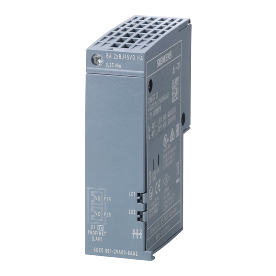
Page 12: Appearance Of The Device
Description of the device 3.2 Appearance of the device Appearance of the device Figure 3-1 BusAdapter BA 2xRJ45VD HA Accessories Data plug-in connector Component Description Article number IE FC RJ45 plug 180 2X2 RJ45 data plug-in con- 1 connector 6GK1 901-1BB10-2AA0 nector for IE FC cables per package 2x2, 10/100 Mbps,... - Page 13 Description of the device 3.3 Accessories Data line Component Description Article number IE FC TP Standard Cable GP Industrial Ethernet FastConnect Twisted 6XV1 878-2A Pair, shielded TP installation cable for connection to IE FC RJ45 plug 4X2, CAT 6, AWG 24 Sold by the meter IE FC TP Standard Cable GP Industrial Ethernet FastConnect Twisted...
- Page 14 Description of the device 3.3 Accessories Reference identification labels Component Description Article number Figure Reference identifica- The reference identification 6ES7 193-6LF30- tion labels plates (according to EN 81346) 0AW0 can be plugged into every bus adapter, see Manual Collection "Distributed IO system ET 200SP".
-
Page 15: Led Display
Description of the device 3.4 LED display LED display Position The following figure shows the LEDs on the BusAdapter BA 2xRJ45VD HA. ① LK1 (green) ② LED without function ③ LK2 (green) ④ LED without function Figure 3-2 LED displays on the BusAdapter BA 2xRJ45VD HA LEDs LK1/LK2 LEDs LK1/LK2 show the status of the cable connections. - Page 16 Description of the device 3.4 LED display SIMATIC BusAdapter Operating Instructions, 06/2018, C79000-G8976-C472-01...
-
Page 17: Mounting
Mounting Safety notices for installation Safety notices When installing the device, keep to the safety notices listed below. WARNING If a device is operated in an ambient temperature of more than 50 °C, the temperature of the device housing may be higher than 70 °C. The device must therefore be installed so that it is only accessible to service personnel or users that are aware of the reason for restricted access and the required safety measures at an ambient temperature higher than 50 °C. - Page 18 Mounting 4.1 Safety notices for installation WARNING Substitution of components may impair suitability of the equipment. WARNING When used in hazardous environments corresponding to Class I, Division 2 or Class I, Zone 2, the device must be installed in a cabinet or a suitable enclosure. Safety notices for use according to ATEX and IECEx If you use the device under ATEX or IECEx conditions you must also keep to the following safety notices in addition to the general safety notices for protection against explosion:...
- Page 19 Mounting 4.1 Safety notices for installation WARNING Explosion hazard Do not disconnect equipment when a flammable or combustible atmosphere is present. WARNING EXPLOSION HAZARD For operation the device is intended to be installed within an enclosure/control cabinet. The inner temperature of the enclosure/control cabinet corresponds to the ambient temperature of the device.
-
Page 20: Installation Clearances
Mounting 4.2 Installation clearances Further notes CAUTION Use only approved components If you use components and accessories that are not approved for SIMATIC NET devices or their target systems, this may violate the requirements and regulations for safety and electromagnetic compatibility. Only use components approved for the SIMATIC NET devices. -
Page 21: Installation Location
Mounting 4.3 Installation location Installation location The mounting position of the BusAdapter corresponds to the mounting position of the basic device. The following mounting positions are possible: Horizontal Horizontal installation of the rack (DIN rail). Vertical Vertical installation of the rack (DIN rail). Remember that the permitted temperature range depends on the installation position. - Page 22 Mounting 4.4 Mounting bus adapters Required tool: ● Slotted screwdriver, blade width 3 to 3.5 mm ● Torx screwdriver, size T10 Installation Figure 4-1 Mounting bus adapters To fit a bus adapter, follow the steps below: 1. Turn off the power to the device. 2.
-
Page 23: Mounting Tensile Strain Relief
Mounting 4.5 Mounting tensile strain relief 5. If necessary remove the strain relief, see section "Mounting tensile strain relief (Page 23)". 6. Close the bus adapter slot with a cover. Mounting tensile strain relief Required tools ● Torx screwdriver, size T10 ●... - Page 24 Mounting 4.5 Mounting tensile strain relief Removal To remove strain relief from the device, follow the steps below: 1. Release the cable from the strain relief and pull the cable. 2. Remove the bus adapter, see section "Mounting bus adapters (Page 21)". 3.
-
Page 25: Connection
Connection Safety when connecting up Safety notices When connecting up the device, keep to the safety notices listed below. Safety notices on use in hazardous areas General safety notices relating to protection against explosion WARNING EXPLOSION HAZARD Do not connect or disconnect cables to or from the device when a flammable or combustible atmosphere is present. -
Page 26: Wiring Rules
Connection 5.2 Wiring rules WARNING Safety notice for connecting with a LAN ID (Local Area Network) A LAN or LAN segment with all the interconnected devices should be contained completely in a single low voltage power distribution in a building. The LAN is designed either for “Environment A”... -
Page 27: Industrial Ethernet
Connection 5.3 Industrial Ethernet Industrial Ethernet NOTICE The BusAdapter BA 2xRJ45VD HA can only establish a connection to another BusAdapter BA 2xRJ45VD HA. The connection to a standard Ethernet connection is not possible. NOTICE Cable connection between two BusAdapters BA 2xRJ45VD HA Use the same type of cable for the cable connection between two BusAdapters BA 2xRJ45VD HA. - Page 28 Connection 5.3 Industrial Ethernet Autonegotiation Autonegotiation means the automatic detection/negotiation of the transmission rate and the operating mode of ports at the opposite end. This makes it possible to configure different devices automatically. Two components connected to a link segment can exchange information about the transfer and can adapt their settings to each other.
-
Page 29: Assemble Profibus Cable Pb Fc Standard Cable Gp With Data Connector Ie Fc Rj45 Plug 4X2 For 2-Wire Transmission Function
Connection 5.3 Industrial Ethernet Note If you use cables with a length > 500 m, connection establishment can take up to 2 minutes. Note If you connect a BusAdapter BA 2xRJ45VD HA to existing PROFIBUS cabling, the same requirements relating to shield contact and the lightning protection concept apply as for PROFIBUS. - Page 30 Connection 5.3 Industrial Ethernet Requirement ● You are familiar with handling of the stripping tool. Refer to the installation instructions provided with the connector. ● The stripping tool is set to a blade distance of 5.1 mm. Pin assignment for the RJ45 connector of a PROFIBUS cable Note the following when you use the PROFIBUS cable PB FC Standard Cable GP with data connector IE FC RJ45 Plug 4x2: Data connector...
- Page 31 Connection 5.3 Industrial Ethernet Procedure To assemble the PROFIBUS cable PB FC Standard Cable GP with data connector IE FC RJ45 plug 4x2, follow these steps: 1. Strip about 6 cm off the cable using the stripping tool: – Place the cable in the stripping tool. –...
-
Page 32: Power Supply
Connection 5.4 Power supply 4. Insert the color-coded wires into the contact elements of the connector until the wire insulation comes to rest against it. ② Red wire to pin 2 ③ Green wire to pin 1 5. Close the connector and press the two halves together. 6. -
Page 33: Maintenance And Troubleshooting
Maintenance and troubleshooting Device defective If a fault develops, please send the device to your SIEMENS service center for repair. Repairs on-site are not possible. SIMATIC BusAdapter Operating Instructions, 06/2018, C79000-G8976-C472-01... - Page 34 Maintenance and troubleshooting SIMATIC BusAdapter Operating Instructions, 06/2018, C79000-G8976-C472-01...
-
Page 35: Technical Data
Technical data The following technical specifications apply to the BusAdapter BA 2xRJ45VD HA. Technical specifications Attachment to Industrial Ethernet Electrical connectors Quantity RJ45 jack Properties Half/full duplex, MDI-X pinning Without retaining collar Transmission speed 10 / 100 Mbps Permitted cable lengths Copper cable 10 Mbps IE FC TP Standard Cable GP 2X2 with... - Page 36 Technical data Technical specifications Housing, dimensions and weight Housing material Polycarbonate (PC-GF10) Degree of protection IP20 Dimensions (W x H x D) 20 x 69.5 x 59 mm Weight 46 g Mean time between failure (MTBF) MTBF (EN/IEC 61709; > 153 years 40 °C) Ambient temperature during operation The maximum ambient temperature during operation depends on the basic device and the...
-
Page 37: Dimension Drawings
Dimension drawings Note The dimensions are specified in mm. SIMATIC BusAdapter Operating Instructions, 06/2018, C79000-G8976-C472-01... - Page 38 Dimension drawings SIMATIC BusAdapter Operating Instructions, 06/2018, C79000-G8976-C472-01...
-
Page 39: Approvals
You can check which of the following approvals have been granted for your product by the markings on the type plate. Current approvals on the Internet You will find the current approvals for the product on the Internet pages of Siemens Industry Online Support (https://support.industry.siemens.com/cs/ww/en/ps/15273/cert). EC declaration of conformity... - Page 40 Area". You will find this document • on the data medium that ships with some devices. • on the Internet pages of Siemens Industry Online Support (https://support.industry.siemens.com/cs/ww/en/view/78381013). Enter the document identification number C234 as the search term. The SIMATIC NET products meet the requirements of the EC directive 94/9/EC "Equipment and Protective Devices for Use in Potentially Explosive Atmospheres”.
- Page 41 Approvals IECEx The SIMATIC NET products meet the requirements of explosion protection according to IECEx. IECEx classification: Ex nA IIC T4 Gc DEK 14.0025X The products meet the requirements of the following standards: ● IEC 60079-15 (Explosive atmospheres - Part 15: Equipment protection by type of protection "n") ●...
- Page 42 Cl. 1, Zone 2, GP IIC T4 Report no. E240480 Safety of electrical equipment In the version put into circulation by Siemens AG, the SIMATIC NET products described in these Operating Instructions conform to the regulations of the following European directive: ● EN 60950-1 Information technology equipment - Safety - Part 1: General requirements The product meets the requirements of the AS/NZS 2064 standard (Class A).
- Page 43 ● "Industrial Ethernet / PROFINET Industrial Ethernet" System Manual (https://support.industry.siemens.com/cs/ww/en/view/27069465) ● "Industrial Ethernet / PROFINET - Passive Network Components" System Manual (https://support.industry.siemens.com/cs/ww/en/view/84922825) ● "EMC Installation Guidelines" configuration manual (https://support.industry.siemens.com/cs/ww/en/view/60612658)
- Page 44 Approvals SIMATIC BusAdapter Operating Instructions, 06/2018, C79000-G8976-C472-01...
-
Page 45: Index
Index Accessories, 14 Permitted ambient conditions, 35 Ambient conditions, 35 Attachment to Industrial Ethernet, 35 Autonegotiation, 28 AWG, 26 Reference identification label, 14 Cable, 13 Safety notices Cable cross section, 26 for installation, 17 Cross section, 26 general, 9 Use in hazardous areas, 9, 17, 25 when connecting up, 25 SIMATIC NET glossary, 6 Data cable, 13... - Page 46 Index SIMATIC BusAdapter Operating Instructions, 06/2018, C79000-G8976-C472-01...
Need help?
Do you have a question about the SIMATIC BusAdapter BA 2xRJ45VD HA and is the answer not in the manual?
Questions and answers