
Subscribe to Our Youtube Channel
Related Manuals for Thor Broadcast H-IRD-V4


Summary of Contents for Thor Broadcast H-IRD-V4
- Page 1 H-4ATSC-QAM-IP H-IRD-V4 Quad DVB-S/S2 Tuner Integrated Decoder User’s Manual Thor Broadcast Los Angeles CA...
-
Page 2: Table Of Contents
DIRECTORY Chapter 1 Product Outline ................1 1.1 Outline ........................1 1.2 Features ........................1 1.3 Principle Chart ......................2 1.4 Technical Specifications ..................... 2 1.5 Appearance and description ..................3 Chapter 2 Installation Guide ................5 2.1 Acquisition Check ..................... 5 2.2 Installation Preparation .................... -
Page 3: Chapter 1 Product Outline
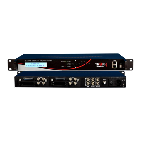
RF output. It is a 1-RU chassis which supports 4 tuner inputs to receive signals from satellite(S/S2), cable or terrestrial (ATSC). To meet customers’ various requirements, the H-4ATSC-QAM-IP / H-IRD-V4 is also equipped with 2 ASI inputs and 1 output with 2 separate ASI ports and 4 MPTS UDP IP ports. The output modulated signals are to be received by TV Tuners, STB’s etc. -
Page 4: Principle Chart
H-IRD-V4 Manual 1.3 Principle Chart Tuner In 1 Demodulator 1 CAM/CI 1/BISS 1 Tuner In 2 Demodulator 2 2*ASI&4MPTSIP Output CAM/CI 2/BISS 2 Tuner In 3 Demodulator 3 CAM/CI 3/BISS 3 Tuner In 4 Demodulator 4 CAM/CI 4/BISS 4 Modulating... -
Page 5: Appearance And Description
H-IRD-V4 Manual bandwidth Local interface LCD + control buttons Remote Web NMS management System 2 ASI out(BNC type) Stream Out IP (4*MPTS over UDP) out (RJ45, 1000M) Upgrading Web and USB Dimension 482mm×300mm×44.5mm(W*D*H) Weight 3.7kg Temperature 0~45℃(Operation) ; -20~80℃(Storage) General Power AC 100V±1050/60Hz;... - Page 6 H-IRD-V4 Manual Rear Panel Illustration Module 1: with 2 CAMs /Smart card slots and 2 RF signal input and loop-through Module 2: with 2 CAMs /Smart card slots and 2 RF signal input and loop-through 2 separate ASI input Interface (BNC)
-
Page 7: Chapter 2 Installation Guide
H-IRD-V4 Manual Chapter 2 Installation Guide 2.1 Contents Check The contents of your new IRD V4 should include the following items: H-IRD-V4 Quad Tuner Decoder 1pcs User’s Manual 1pcs RF/Loopout Cables 4 PCs ASI Cable 1pcs ... - Page 8 H-IRD-V4 Manual 2.2.2 Environment Requirement Item Requirement Electric Isolation, Dust Free Volume resistivity of ground anti-static material: Machine Hall Floor 10 ,Grounding current limiting resistance: 1X10 ~1X10 1M (Floor bearing should be greater than 450Kg/㎡) 5~40℃(sustainable ),0~45℃(short time), Environment Temperature...
-
Page 9: Wire's Connection
H-IRD-V4 Manual 2.3 Wire’s Connection The grounding wire conductive screw is located at the right end of rear panel, and the power switch, fuse, power supply socket is just beside it, order goes like this, power switch is on the left, power supply socket is on the right and the fuse is just between them. - Page 10 H-IRD-V4 Manual ASI Input Cable Illustration:...
-
Page 11: Chapter 3 Operation
H-IRD-V4 Manual Chapter 3 Operation The front panel of the Thor Broadcast H-IRD-V4 is the user-operating interface and the equipment can be easily managed by anyone according to the directions displayed on the LCD: Keyboard Function Description: MENU: Cancel current entered value, resume previous setting; Return to previous menu. -
Page 12: Lcd Menu Tree
H-IRD-V4 Manual 3.1 LCD Menu Tree... - Page 13 H-IRD-V4 Manual Card A: Main Menu CI Card: Max Birate CI Card Card A Input TS Mode Card Error Check Parse Program Descramble Program Rom Version Card Status Descramble Error CI Card: ‘ ’ (Same content with Card A above)
- Page 14 H-IRD-V4 Manual Main Menu: IP Stream: Service IP IP Stream Service IP xxx.xxx.xxx.xxx IP Stream: Subnet Mask Subnet Mask xxx.xxx.xxx.xxx IP Stream: Gateway Gateway xxx.xxx.xxx.xxx IP Stream: MPTS: MPTS 1 Data enable Null PKT Filter Output IP Output Port (Same submenus with...
-
Page 15: General Setting
H-IRD-V4 Manual 3.2 General Setting Switch on the device and after a few seconds’ initialization, it presents start-up pictures as shown below: H-IRD-V4 Quad Tuner Start OK… Start up… A Bitrate xx.xxMbps Indicates the Real-time output bitrate of the 2 carriers, which shows in turn. - Page 16 H-IRD-V4 Manual Uptime Press Enter to enter “Status” and it displays the working time duration of the device. It times upon power on Uptime 2 Days-10:30:20 3.2.2 Input Sets 2 Days-10:30:20 The IRD-V4 supports 4 tuner inputs and 2 ASI inputs. Please connect the signals to the input interfaces and enter ‘Input Sets’...
- Page 17 H-IRD-V4 Manual Mux Program: Parse the Tuner input program list and select programs to mux out via the 4 carriers in this menu. For reading the input bitrate TS Locked Mux Program of corresponding channel Bitrate: 4.040 Mbps TS Lock...
- Page 18 H-IRD-V4 Manual CI Card Card A Card B Card C Card D Press ENTER key to enter Card A (or Card B/C/D), the setting principle is the same. Card A Max Bitrate Input TS Mode Card Error Check Parse Program...
- Page 19 H-IRD-V4 Manual Decide whether to enable or disable the card error check function in this menu. Card Error Check (1/2) ► Enable Parse Program Read the quantity of programs parsed from the de-scrambled channel. Searching Program Get 8 Programs ...
- Page 20 H-IRD-V4 Manual Press ENTER key to enter BISS A (or BISS B/C/D), the setting principle is the same: BISS A Input TS Mode Word Mode Burned Key Descrambler Key TS Lock Parse Program Descramble Program Input TS Mode One BISS can be applied to descramble one corresponding Tuner input signal sources.
- Page 21 H-IRD-V4 Manual Parse Program Read the quantity of programs parsed from the de-scrambled channel. Searching Program Get 7 Programs Descramble Program Select program(s) from the searched out programs to descramble. ►1 CETV 1 √ 2 CCTV 4A 3.2.5 TS Config Enter ‘TS Config’...
- Page 22 H-IRD-V4 Manual Tuners, 2 ASI and 1USB input ports. Output Mode (1/8) To output muxed programs Tuner 1 To output programs from Tuner 2 Tuner x without mux Tuner 3 Tuner 4 output programs ASI 1 from ASI x without mux...
- Page 23 H-IRD-V4 Manual 3.2.6 Modulate Settings When entering “Modulate Settings” submenu, configure the modulating parameters for the 4 carrier outputs separately. Modulate Chanel A Chanel B Chanel C Chanel D Standard Constellation Symbol rate RF Frequency RF Level RF On Bitrate ...
- Page 24 H-IRD-V4 Manual Check symbol rate here. Symbol rate 5310 Ksps RF Frequency The RF output frequency range is from 30 to 950MHz with 1K stepping. After entering the RF frequency setting submenu, press LEFT, RIGHT, UP, and DOWN buttons to adjust the frequency and confirm by press ENTER button.
- Page 25 H-IRD-V4 Manual 3.2.5 IP Stream TS to output in IP (4*MPTS) format through the DATA port. Users can set IP output parameters in this menu. IP Stream: Service IP Subnet Mask Gateway MPTS 1 MPTS 2 MPTS 3 MPTS 4 3.2.7 USB Device...
- Page 26 H-IRD-V4 Manual Play Play Search File Play list Play Mode Search File: read the quantity of programs in the USB. Play list: view program list in the USB device. Play Mode: select a play mode for the *.ts files as needed before playing the *.ts file and specify a video under ‘Single file’...
- Page 27 H-IRD-V4 Manual 3.2.8 Network Set network parameters in this menu. Enter ‘Network’ submenus to separately set corresponding parameters. Network NMS IP Subnet Mask Gateway MAC Address Web NMS Port Reset Password NMS IP The IP address for connecting 192.168.000.136 the device to PC Subnet Mask 255.255.255.000...
- Page 28 H-IRD-V4 Manual System Save Config Load Saved CFG Factory Reset LCD Time-out Key Password Lock Keyboard Product ID Version Save Configuration? Choose yes to save settings. and press ENTER to confirm Choose yes to restore the Load Saved CFG? device into the last saved configuration.
-
Page 29: Chapter 4 Web-Based Nms Management
H-IRD-V4 Manual Chapter 4 Web-based NMS Management In addition to using the front buttons to control the device, you can also control and set the configuration with the web browser in the PC. Mozilla and Internet Explorer work best. 4.1 login The default IP address of this device is 192.168.0.136. - Page 30 H-IRD-V4 Manual can have an overview of the device’s system information and working status. System information Input information of the 4 Tuner, 2 ASI and USB input channels Output information: Indicators—Green light indicates the TS is normal, which User can click any item here to enter otherwise turns to red.
- Page 31 H-IRD-V4 Manual Click “TS Config”, it displays the interface where users can configure the output TS parameters in this interface. (Figure-4) Output carrier select The letters A, B, C and D represent the 4 carriers soutputs. To choose output programs for the 4 carrier output Mux:To output muxed...
- Page 32 H-IRD-V4 Manual (Figure-6) Output Area Input Area Operation Area Figure-6 Configure ‘Input Area’ and ‘Output Area’ with buttons in ‘Operation Area’. Instructions are as below: : To enable/disable the PID remapping To refresh the input program information To refresh the output program information Select one input program first and click this button to transfer the selected program to the right box to output.
- Page 33 H-IRD-V4 Manual Figure-7 Input new data and click ‘Save’ button at last to confirm the modification. Parameters → CI Card: The IRD V4 also supports 4 CI cards to descramble programs from Tuner inputs. Click and enter ‘CI Card’ to configure the 4 cards respectively. (Figure-8)
- Page 34 H-IRD-V4 Manual Input TS Mode One CI card can be applied to descramble programs from the 2 Tuner input signal sources. ‘Skip CI card’ means to skip the card which is used for FTA stream. Card Error Check Decide whether to enable the card error check function by checking the box.
- Page 35 H-IRD-V4 Manual Number before slash indicates the programs which have been descrambled. Number behind slash indicates the whole programs from the selected channel. Users can also read the program information by clicking ‘+’ symbol. Parameters → BISS: From the menu on left side of the webpage, clicking “BISS”, it displays the interface where users can configure 4 BISS and descramble the input channels.
- Page 36 H-IRD-V4 Manual Input corresponding items and data to active the BISS descrambling as principles be Modulating Side (BISS SCR) Receiving Side (BISS DESCR) Digit (0x----) Mode 1+SW Data Mode 1+Descrambler Key Mode E+ESW Data + Device Mode E + Descrambler Key + Burned Key...
- Page 37 H-IRD-V4 Manual Parameters → PID Pass: From the menu on left side of the webpage, clicking “PID Pass”, it displays the interface where to add the PIDs which need pass through. (Figure-12) In some occasions, there are some PIDs which won’t belong to any program, such as EPG, NIT tables and so on which user just wants to pass them through the multiplexing module without changing anything.
- Page 38 H-IRD-V4 Manual Figure-15 System → USB From the menu on left side of the webpage, clicking “USB Media”, it displays the interface where users can operate USB device. (Figure-16) NOTE: It is necessary to connect USB device and signal source and activate modulating to operate TS recording.
- Page 39 H-IRD-V4 Manual Detailed Explanation: Play Mode: You can select a play mode for the *.ts files as needed before playing the *.ts file and specify a video under ‘Single file’ / ‘Single loop’ mode and press “Enter” button to start play. While under ‘Play all’ / ‘Loop all’ mode, it automatically plays files from first to end.
- Page 40 H-IRD-V4 Manual System → LCD/Keyboard: From the menu on left side of the webpage, clicking “LCD/Keyboard”, it will display the screen as Figure-18 where to control the device’s front panel. Figure-18 Keyboard and LCD Lock: If it is marked with “√”,the LCD and keyboard will be locked to avoid unexpected modification or view of the device information and configurations.
- Page 41 H-IRD-V4 Manual Figure-20 System → Backup/Load: From the menu on left side of the webpage, clicking “Backup/Load”, it will display the screen as Figure-21 where to backup or load your configurations. Figure-21 System → Firmware: From the menu on left side of the webpage, clicking “Firmware”, it will display the...
- Page 42 H-IRD-V4 Manual Figure-22...
-
Page 43: Chapter 5 Troubleshooting
H-IRD-V4 Manual Chapter 5 Troubleshooting THOR’s ISO9001 quality assurance system has been approved by the CQC organization. We guarantee the products’ quality, reliability and stability. All Thor Broadcast / Thor Fiber products haven passed all testing and manual inspections before they are shipped out. The testing and inspection scheme already covers all the Optical, Electronic and Mechanical criteria which have been published by THOR. -
Page 44: Chapter 6 Packing List
H-IRD-V4 Manual Chapter 6 Packing List Thor Broadcast IRD-V4 1pcs User’s Manual 1pcs RF/Loopout Cables 4pcs ASI Cable 1pcs Power Cord 1pcs...
Need help?
Do you have a question about the H-IRD-V4 and is the answer not in the manual?
Questions and answers