Table of Contents
Advertisement
Quick Links
Installation instructions for Network Thermostat Controller Kits (17M10 and 16H99) used with
Application ....................................................................1
Shipping and Packing List ...........................................2
Installation .....................................................................2
Roof Top Units .............................................................2
Commercial Split Systems ..........................................3
Heartbeat LED ...............................................................3
Pushbutton ....................................................................3
Manual Output Test Switches ......................................3
Unit Address DIP Switches ..........................................3
Configuration DIP Switches ........................................3
Types of Units - Switches 1 and 2 ...............................3
Number Of Cooling Stages − Switches 3 and 4 ..........4
Number Of Heating Stages − Switches 5 and 6 ..........4
Local or Remote System Mode ...................................4
Local Sensor ...............................................................4
Remote Sensor ...........................................................4
Sensor Back−Up Operation ........................................4
Operation ....................................................................5
Blower Operation ........................................................5
Network Control Panel (NCP) Setpoints .....................5
L Connection Network Setpoints .................................5
Remote Sensor Data Interruption ...............................5
Off Delay .....................................................................5
Discharge Air Control System Mode ..........................6
Operation ....................................................................6
Back−Up Operation .....................................................6
Digital Outputs − P181 and P182 ................................7
Temperature Sensors - P178 .......................................8
CONTROLS
KITS AND ACCESSORIES
507796-01
8/2018
Supersedes 11/2017
Units not Equipped with a Unit Controller
Table of Contents
Network Thermostat Controller
WARNING
Improper installation, adjustment, alteration, service or
maintenance can cause property damage, personal
injury or loss of life.
Installation and service must be performed by a licensed
professional installer (or equivalent) or service agency.
Application
The NTC unit controller is used on units not equipped
with a rooftop unit controller (i.e. [IMC M1−x, M2 or
M3 Prodigy
Unit Controller]) to allow access to the L
®
Connection
Network. The NTC may be used to control
®
rooftop packaged equipment or split systems and is
compatible with the Network Control Panel (NCP) versions
2.00 or later and Unit Controller (UC) software versions
2.08 or later. The NTC can control up to three stages of
cooling, two stages of heating, the blower, and outdoor air
dampers.
Local Zone Sensor A2 .................................................8
Return Air Sensor RT16 ..............................................8
Discharge Air Sensor RT6 ...........................................8
Outdoor Air Sensor RT17 ............................................8
Analog Inputs - P179 ....................................................8
C02 and Relative Humidity Sensor .............................8
Damper Feedback .......................................................8
Digital Inputs - P177 .....................................................8
Air Flow Switch ............................................................8
Service Input ...............................................................8
N.C. Normally Closed Input .........................................8
N.O. Normally Open Input ...........................................9
Check−Out Procedure ..................................................9
Unit Operation .............................................................9
Wiring Between NTC And Unit ....................................9
NTC Operation ............................................................9
Adjustable Parameters.................................................9
Reset NTC Parameters to Default .............................10
Error Codes .................................................................12
Wiring ..........................................................................13
24VAC .......................................................................13
Communication Wiring ..............................................13
Typical NTC1−1 (A113) Field Wiring .........................13
ELA Unit Accessories Wiring Diagram ......................14
General Application (2 Heat and 3 Cool) ...................15
NTC1-1- Kit
Advertisement
Table of Contents

Subscribe to Our Youtube Channel
Related Manuals for Lennox NTC1-1-Kit


Summary of Contents for Lennox NTC1-1-Kit
-
Page 1: Table Of Contents
CONTROLS KITS AND ACCESSORIES Network Thermostat Controller 507796-01 8/2018 NTC1-1- Kit Supersedes 11/2017 Installation instructions for Network Thermostat Controller Kits (17M10 and 16H99) used with Units not Equipped with a Unit Controller WARNING Improper installation, adjustment, alteration, service or maintenance can cause property damage, personal injury or loss of life. -
Page 2: Shipping And Packing List
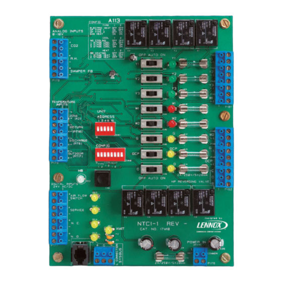
OFF AUTO ON FUSES (8) 2 AMP/250V/5X20mm UNIT ADDRESS DIP SWITCHES THERMOSTAT OUTPUT UNIT LED’S (8) ADDRESS 1 2 4 8 16 MANUAL OUTPUT TEST CONFIGURATION SWITCHES (8) DIP SWITCHES CONFIG 1 2 3 4 5 6 7 8 HEARTBEAT LED 24VAC POWER FUSE DIGITAL INPUT LED’S (4) (2 AMP/250V/5X20mm) -
Page 3: Commercial Split Systems
ommeRCial pliT ysTems 1. Disconnect all electrical power to the unit. 2. Mount the enclosure in a convenient location near the control box. AUTO 3. Secure the NTC1 baseplate to the enclosure using the screws provided. IMPORTANT Do not remove the NTC1−1 baseplate. Figure 3. -
Page 4: Number Of Cooling Stages − Switches 3 And 4
(A2) valve. Most residential heat pumps operate in this Figure 6. Local Sensor manner. Connect Lennox residential heat pumps to O” output. • Electric Cool / Gas Heat Units - Standard electric cool emoTe ensoR / gas heat unit. -
Page 5: Operation
• Cooling setpoint: 75°F (ECTO A2.01) peRaTion • Heating setpoint: 70°F (ECTO A1.01) In local or remote sensor mode, default operation, the NTC ECTO A1.01 and A2.01 back−up setpoints are used NTC controls up to two stages of heating and three stages when the communication link has been lost on the L of cooling. -
Page 6: Discharge Air Control System Mode
The NTC will operate in Discharge Air Control (DAC) Stages − Default Values Shown” on page 7for DACH system mode only when used with a Lennox Zone Link as heating stages. part of a zoning system. Refer to the Zone Link installation IMPORTANT instruction. -
Page 7: Digital Outputs − P181 And P182
110°F + 5°F 5°F H1=Heating Stage 1 ECTO A4.08 + A4.09 DACH Deadband H2=Heating Stage 2 (All Stages Same Setting) ° ° ° F − 2 F + 5 ECTO A4.09 − A4.12 + A4.09 110°F Default Occupied DACH Setpoint ECTO A4.08 °... -
Page 8: Temperature Sensors - P178
elaTive UmidiTy ensoR Table 9. Heat Pump Units Type 2 NTC Digital Output The CO2 and RH sensors are optional and are used for Thermostat reporting and displaying to the Network Control Panel only. P181 P182 Demand ampeR eedBaCk 1st Cool 2nd Cool The Damper FB input is optional and used for reporting and displaying to the Network Control Panel only. -
Page 9: Normally Open Input
− − − SYS BUS SYS BUS SYS BUS ON NTC ON NTC ON LAST Shield Shield Shield SYS BUS ON NCP CONNECT + TERMINALS OF NCP TO + TERMINALS ON THE NTC SYS BUS TERMINAL BLOCK. CONNECT − TERMINALS OF NCP TO −TERMINALS ON THE NTC SYS BUS TERMINAL BLOCK. Shield −... -
Page 10: Reset Ntc Parameters To Default
Reset NTC Parameters to Default Restore the NTC controller parameters to default settings as follows: 1. Disconnect power to NTC (P176). CONNECT FIELD−PROVIDED PHONE CORD TO PHONE 2. Move all DIP switches on the Unit Address DIP switch JACK ON NTC OR NCP to OFF. - Page 11 Table 10. NTC Controller Parameters Control Value Control Parameter Name Units Description A2.05 Cooling Deadband 3.75 Deg. F Cooling stage deadband. A2.05 <=A4.03−A1.04 Upper Stage Cooling A2.06 Option Option used to hold upper stage on until lower stage demand is satisfied. Latch Option Optional timer used to call the upper demand if the lower stage runs for this A2.07...
-
Page 12: Error Codes
Table 10. NTC Controller Parameters Control Value Control Parameter Name Units Description A4.13 DACC_SP Deg. F Discharge air control cooling setpoint. A4.14 DACC_Stg_DB Deg. F Discharge air control cooling stage deadband. A4.15 DACC_StgUp_Dly Discharge air control cooling stage−up time delay. A4.16 DACC_StgDn_Dly Discharge air control cooling stage−down time delay. -
Page 13: Wiring
Wiring Cable type: Lennox P/N 94L63 or 27M19, Belden type All wiring must comply with local electrical code or as 88761 or equivalent. (22AWG stranded or twisted pair, specified on the unit wiring diagrams. Refer to figure 1 100% aluminum shield with drain wire, Teflon jacket). -
Page 14: Ela Unit Accessories Wiring Diagram
ela U CCessoRies iRing iagRam A113 COOL 2-Y2 A113 CONTROL-NETWORK THERMOSTAT JACK-EXHAUST FAN RELAY-EXHAUST FAN PLUG-EXHAUST FAN SENSOR-MIXED OR SUPPLY AIR SWITCH-AIRFLOW 10/17 ELA UNITS TEMPERATURE CONTROL SECTION C REV 0 Supersedes Form No. New Form No. 537942-01 2008 Litho U.S.A. Figure 14. -
Page 15: General Application (2 Heat And 3 Cool)
(2 h eNeral ppliCatiON eat aNd Figure 15. General Application (2 Heat and 3 Cool) Page 15... -
Page 16: General Application (2 Heat And 3 Cool Heat Pump)
(2 h eNeral ppliCatiON eat aNd Figure 16. General Application (2 Heat and 3 Cool Heat Pump) Page 16...
Need help?
Do you have a question about the NTC1-1-Kit and is the answer not in the manual?
Questions and answers