Advertisement
Quick Links
E2011
Litho U.S.A.
INSTALLATION & SETUP GUIDE FOR THE M2 UNIT CONTROLLER
Use arrows to move
DISPLAY
SERVICE
ALARM
STATUS
OFFLINE
MODE
IN/OUTPUTS
CALLS
REPLACE
USB
REPORT
M2 UNIT CONTROLLER
t Listed
BACnet
R
USB CONNECTION
(for Unit Controller
Description
The Prodigyt M2 unit controller:
S
provides control functions for Energencet roof-
top unit,
S
includes a user interface consisting of a dot ma-
trix display, navigation arrow buttons, a select
button, and a USB port,
S
provides status & diagnostic information for trou-
bleshooting,
S
allows adjustment of time delays and setpoints
that enable advanced features,
S
is controlled by a standard room thermostat, di-
rect digital controller (DDC), or a zone sensor,
S
can be configured as a device on the network
when daisy−chained to the L Connection
work,
S
may be connected to a PC which has been
loaded with Unit Controller software,
S
accepts add−on boards to build variations ac-
cording to application or equipment type.
S
USB
verification and profile sharing.
06/11
*2P0611*
506215−01
06/11
Supersedes 12/09
USED WITH ENERGENCEt ROOFTOP UNITS
Push to select or enter value; then use
arrows
DATA
SETTINGS
TEST
RUNTIMES
UNIT
HISTORY
SETPOINTS
SENSORS
CONTROL
NETWORK
OPTIONS
FACTORY
INSTALL
L CONNECTION ( optional
connection method for Unit
software)
Controller software)
®
DISPLAY
DISPLAY
USER INTERFACE NAVIGATION ARROWS
USER INTERFACE NAVIGATION ARROWS
SMARTWIREt
CONNECTORS
Table Of Contents
M2 unit controller, expansion board locations,
SmartWiret connections
M2 unit controller LED operation indications
Startup
. . . . . . . . . . . . . . . . . . . . . . . . . . . . . . . . . . . . . . . . . . . .
Menu interface
. . . . . . . . . . . . . . . . . . . . . . . . . . . . . . . . . . . . .
Operation:
DISPLAY
. . . . . . . . . . . . . . . . . . . . . . . . . . . . . . . . . . . . . .
GUIDED SETUP
SERVICE
. . . . . . . . . . . . . . . . . . . . . . . . . . . . . . . . . . . . . .
TEST
. . . . . . . . . . . . . . . . . . . . . . . . . . . . . . . . . . . . . . . . .
DATA
. . . . . . . . . . . . . . . . . . . . . . . . . . . . . . . . . . . . . . . . .
SETTINGS
INSTALL NEW M2
Economizer (Damper)
APPENDIX:
Net-
Abbreviations
Parts List
. . . . . . . . . . . . . . . . . . . . . . . . . . . . . . . . . . . . . .
USB Service Report Example
Alarm Codes
Wiring Diagrams
M2 unit controller signal reference diagram
M2 unit controller board connections diagram
QUICK START GUIDE (BACK COVER)
Page 1
PRODIGYt
M2 Unit Controller
USB
USB
INTERFACE
INTERFACE
PORT
PORT
(For Flash Drive)
SELECT
SELECT
BUTTON
BUTTON
. . . . . . . . . . . . . . . . . . . . . . . .
. . . . . . . . . . . .
. . . . . . . . . . . . . . . . . . . . . . . . . . . . . . .
. . . . . . . . . . . . . . . . . . . . . . . . . . . . . . . . . . . .
. . . . . . . . . . . . . . . . . . . . . . . . . . . . . .
. . . . . . . . . . . . . . . . . . . . . . . . . . . . . . .
. . . . . . . . . . . . . . . . . . . . . . . . . . . . . . . . . .
. . . . . . . . . . . . . . . . . . . .
. . . . . . . . . . . . . . . . . . . . . . . . . . . . . . . . . . .
. . . . . . . . . . . . . . . . . . . . . . . . . . . . . . . .
. . . . . . . . . . . .
506215−01
*P506215-01*
2
3
3
5
6
8
10
11
12
13
17
18
20
20
21
22
25
. . . . . . . . .
30
. . . . . . .
31
32
Advertisement

Related Manuals for Lennox Prodigy


Summary of Contents for Lennox Prodigy
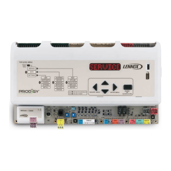
- Page 1 PRODIGYt 506215−01 06/11 M2 Unit Controller Supersedes 12/09 E2011 Litho U.S.A. INSTALLATION & SETUP GUIDE FOR THE M2 UNIT CONTROLLER USED WITH ENERGENCEt ROOFTOP UNITS DISPLAY Push to select or enter value; then use Use arrows to move arrows DISPLAY INTERFACE INTERFACE PORT...
- Page 2 M2 (A55) unit controller − location, controls, inputs/outputs M2 unit controller board, expansion board locations, SmartWiret connections Figure 1 shows the controller components and the locations for expansion boards. CONTROL CONTROL BOARD BOARD EXPANSION EXPANSION PORT PORT ECONOMIZER POTS 2 AMP FUSE USB CONNECTION AND DIP SWITCHES (for Unit Controller...
- Page 3 F1. This fuse is a standard 2−amp, automotive−style blade fuse. This fuse Sensor Common Isolation protects the Prodigy controller from field wiring mis−wires. Thermostat (TSTAT) and humidity (HUM) sensor com- mons may be isolated if they are powered remotely. Slide TSTAT COM The switch "TSTAT COM"...
- Page 4 Startup (continued) User interface menu tom of the left column in figure 2. For example, if an alarm is present, that will be displayed until it has been silenced or The user interface is accessed through the menu naviga- cleared. tion arrows and the select button .
-
Page 5: Menu Interface
Menu Interface Table 2 shows the major levels of the menu interface. Table 2. Menu Interface (cont’d) Many of these options have more levels and are described Level 1 Level 2 Level 3 in the following sections that detail DISPLAY, SERVICE, DATA, and SETTINGS. -
Page 6: Display Interface
DISPLAY Interface DISPLAY The display shows operating mode if in normal operation. Unit Operation Alarm, status, calls and plugging in the USB will interrupt This section describes the display and control buttons, the display. Alarm messages will stay displayed until cor- how to configure the unit, and how to read stored configu- rected or silenced using the local menu. - Page 7 Multiple units may use the same USB drive. The filename of the service reports will be based on the unit’s serial num- When the Lennox USB drive is plugged in during normal ber; for example 5608J5875.txt. The filename of the unit MODE, a menu will be displayed providing options to save profiles will be based on the unit’s catalog number;...
-
Page 8: Guided Setup
GUIDED SETUP Menu Interface GUIDED SETUP Upon initial unit start−up, the M2 Unit Controller’s menu in- This guided setup is available at any time should you wish terface defaults to a GUIDED SETUP. This setup is de- to go back through and re−configure the system’s setup pa- scribed on this and the following page. - Page 9 GUIDED SETUP Menu Interface GUIDED SETUP (Continued) (SYSTEM CHECKS UNIT CONFIGURATION AND PROMPTS THE USER FOR ONLY THE INSTALLED OPTION[S].) CHANGE SETUP MSAV MSAV MSAV HIGH SPEED XXX% MSAV LOW SPEED XXX% ! SET ! SETTINGS EQUIP- MENT CHANGE HUMIDITROL SET HUMIDITROL OCC/BLOWER SETTINGS...
- Page 10 SERVICE Menu Interface SERVICE From the DISPLAY mode, press and then use SERVICE > IN / OUTPUTS scroll to SERVICE. Next, press to enter the SERVICE In the SERVICE menu, use until IN / OUTPUTS is dis- menu. Use until desired item is displayed. played.
- Page 11 SERVICE Menu Interface SERVICE (Continued) SERVICE > TEST (Continued) Table 4. TEST TEST NOTE: Unit configuration determines which menu GUIDED items are displayed BLOWER BLOWER HI BL OFF/ON Run blower on maximum speed BLOWER LOW BL OFF/ON Run blower on minimum speed PROVING SWITCH PSW CLO Display status of the switch with blower low speed.
- Page 12 DATA Menu Interface DATA From the DISPLAY mode, press and then use DATA > HISTORY scroll to DATA. Next, press to enter the DATA menu. In the DATA menu, use until HISTORY is displayed. until desired item is displayed. Press to enter the HISTORY menu.
- Page 13 DATA Menu Interface DATA (Continued) DATA > NETWORK DATA > STATUS In the DATA menu, use until NETWORK is displayed. In the DATA menu, use until STATUS is displayed. Press to enter the NETWORK menu. Read the NET- Press to enter the STATUS menu. WORK addresses stored in the M2 unit controller.
- Page 14 SETTINGS Menu Interface SETTINGS (Continued) SETTINGS > UNIT SETTINGS > SETPOINTS > DAMPER In the SETTINGS menu, use until UNIT is displayed. Use SETTINGS > SETPOINTS > DAMPER as shown in Press to enter the UNIT menu. View and change the the following diagram;...
- Page 15 SETTINGS Menu Interface SETTINGS (Continued) SETTINGS > CONTROL SETTINGS > CONTROL > LOCAL In the SETTINGS menu, use until CONTROL is dis- (Used in absence of thermostat or network control) played. Press to enter the CONTROL menu access/ change system setpoints. Select SETTINGS >...
- Page 16 SETTINGS Menu Interface SETTINGS (Continued) SETTINGS > CONTROL > BACNET Select SETTINGS > CONTROL > BACNET as shown in the following diagram; default settings will be used. You may adjust those settings to suit the building’s requirements. The following diagram shows the BACNET menu’s structure and how to make changes.
- Page 17 SETTINGS Menu Interface SETTINGS (Continued) SETTINGS > CONTROL > SMOKE MODE SETTINGS > INSTALL > (all except NEW M2) Use SETTINGS > INSTALL as shown in the following dia- When you select SMOKE MODE, default settings will be in gram; default settings will be used. Use menu to change place.
- Page 18 These settings are not accessible through the Prodigy display at this time. On a cooling demand, outdoor air is used for free cooling The unit does not have to be operating in discharge air instead of first−stage compressor(s) when outdoor air is...
- Page 19 Economizer (Damper) (Continued) Mode Outdoor air is suitable for free cooling when: TEMP OFFSET Outdoor air temperature (RT17) is less than return air temperature (RT16) by at least the OFFSET value. TEMP OAT STPT Outdoor air temperature (RT17) is less than the OAT STPT value. Either of the TEMP modes can be used when a network OAS signal is provided by an energy management or building Remote control system, via BACnet, LonTalk, or L Connection.
- Page 20 M2−1 Display battery (10−pack) 59W53 SmartWiret Field Termination kit 59W57 MCB1 M2 Motor Control Replace- 59W50 M2−1 Fuse (2−Amp ATC, 5−pack) 59W54 Lennox Prodigyt USB Memory 59W59 ment kit Stick (5−pack) M2 BACnett Replacement kit 59W51 M2 Deluxe Training kit (suitcase, 59W55 Service Software &...
- Page 21 USB Service Report Example ========================================================================== USB SERVICE REPORT ========================================================================== Service Date 1/1/2010 Service Time 12:00:00 Serial No. 5609K00002 Version 7.02.00 DB1Version 1.05.00 Unit No. Sbus Address BACnet Address. CAT No. NO CN MODEL NO. LGH036H4ES1Y Status HEATING ========================================================================== Runtime Data Total Power On 1832 HRS 79 CYCLES...
- Page 22 Display Message Action ALARM(1) ERRATIC POWER CHECK POWER CONNECTIONS ALARM(2) CHECK SETTINGS RESET CONTROLLER. CHECK UNIT SETTINGS. CONTACT LENNOX IF PROBLEM PERSISTS. Reserved ALARM(3) SMOKE A173 SMOKE MODE. CHECK FOR SOURCE OF SMOKE. ALARM(4) BLOWER S52 UNIT OFF. AIR FLOW SWITCH OPEN 16 SEC AFTER DEMAND. CHECK BLOWER PARTS...
- Page 23 Table 7. Alarm Codes Event Event Code Code Display Message Action ALARM(44) GAS VALVE ON NO DEMAND GV1 UNIT OFF. GV1 POWER BUT NO DEMAND. CHECK GAS PRESS, GAS VALVE ALARM(45) GAS VALVE ON NO DEMAND GV3 UNIT OFF. GV3 POWER BUT NO DEMAND. CHECK GAS PRESS, GAS VALVE 46 −...
- Page 24 ALARM(103) ADVANCED CONTROL SETUP ERROR CHECK PRODIGY SETTINGS Reserved ALARM(105) ADVANCED ECON CONTROL SETUP ERROR CHECK ECON SWITCHES, DIALS, AND PRODIGY SETTINGS ALARM(106) BUILDING PRESS SENSOR A34 CHECK SENSOR AND WIRING ALARM(107) DUCT SUPPLY PRESS SENSOR A30 CHECK SENSOR AND WIRING...
- Page 25 Wiring Diagrams (036, 048, 060 Units) DESCRIPTION COMPONENT MONITOR, PHASE PROTECTION CONTROL, MAIN PANEL LENNOX PANEL, MOTOR CONTROL A169 COMPRESSOR 1 MOTOR, BLOWER MOTOR, OUTDOOR FAN MOTOR, EXHAUST FAN CAPACITOR, COMPRESSOR CAPACITOR, EXHAUST FAN CAPACITOR, COMPRESSOR HARD START CIRCUIT, BREAKER...
- Page 26 ACCESSORIES PLUG, RT6 SUPPLY AIR SENSOR P100 PLUG, SMOKE DETECTOR ONE P250 PLUG, SMOKE DETECTOR ONE P251 PLUG, SMOKE DETECTOR TWO P252 PLUG, SMOKE DETECTOR TWO P253 PLUG, MODULE, CONTROL SMOKE DETECTION P255 PLUG, ECONOMIZER P262 Lennox Commercial Page 26...
- Page 27 Wiring Diagrams (ACCESSORIES) J299A P299 DI−1 USE DI2 TO CONNECT: 1. OVERLOAD CONTACTS DI−2 S135A DI−3 S149 DI−4 USE DI3 TO CONNECT: 1. OVERFLOW SWITCH 2. PHASE MONITOR MODULE P304 A130 TB37 Page 27...
- Page 28 Wiring Diagrams (240, 300 Units) Page 28...
- Page 29 COMPONENT COMPONENT PANEL, MAIN K2,−1 CONTACTOR, COMPRESSOR 2 PANEL, COMPRESSORS 3 AND 4 K3, −1 CONTACTOR, BLOWER COMPRESSOR 1 K10,−1,2 RELAY, OUTDOOR FAN 1 COMPRESSOR 2 K14,−1 CONTACTOR, COMPRESSOR 3 MOTOR, BLOWER K65−1,2 RELAY, EXHAUST FAN MOTOR, OUTDOOR FAN 1 K68,−1 RELAY, OUTDOOR FAN 2 MOTOR, OUTDOOR FAN 2...
- Page 30 Table 8. M2 unit controller signal reference diagram 24VAC 24 VAC COM S − BUS P297 P298 P299 − MS 9413−03−401 MS 9413−10−407 MS 9413−10−408 MS 9413−10−409 Pin # Label Description Type Description Part Number P297 Thermostat Assembly MS 9413−10−407 TRANSFORMER 1 24VAC POWER 24VAC Header &...
- Page 31 Table 9. M2 board connections diagram Pin# Label Description Type P262 Economozer control 24VAC Power 24 VAC Digital Ground 24 VAC COM Damper Control 2−10 VDC AO DPOS Damper Position Feedback 2−10 VDC AI Digital Ground RES 0−5 VDC RT16+ Return Air Temp Relay Outdoor Fan 2 24 VAC DO...
- Page 32 (Page 15). Humidity control requires sensor or error code 76 MSAV Change motor torque; see Use LENNOX MSAV trained technician. SETTINGS −> CONTROL −> LOCAL Final motor CFM needs to be set by Test and (Page 16). Balance technician Blower charts are located in unit EHB.
Need help?
Do you have a question about the Prodigy and is the answer not in the manual?
Questions and answers