Table of Contents
Advertisement
Quick Links
Advertisement
Table of Contents

Related Manuals for Lennox HYDRON Series


Summary of Contents for Lennox HYDRON Series
- Page 1 Библиотека СОК INSTALLATION-OPERATION & MAINTENANCE MANUAL LINE HYDRON...
-
Page 2: Table Of Contents
TABLE OF CONTENTS CONTENTS PAGE • GENERAL DESCRIPTION • KEYPAD • PARAMETERS, STATUS AND READINGS • DEVICE STATUS TABLE • ALARM CODES • THERMOSTAT FUNCTION • DEFROST SYSTEM DESCRIPTION • CONDENSATION CONTROL SYSTEM DESCRIPTION • ALARM AND LOW WATER TEMPERATURE DEVICE DESCRIPTION •... -
Page 3: General Description
GENERAL DESCRIPTION This equipment is an electronic device that controls packaged water cooling systems via air and reversible air/water heat pumps. Its main characteristic is that it performs the functions normally associated with external equipment, thus eliminating the need for additional electrical connections. The main features include water temperature control for cooling and heating, automatic defrost control (heat pump units), low water temperature protection system in the water system, compressor activation idling, constant proportional control of the condenser fan speed and a diagnostic display. -
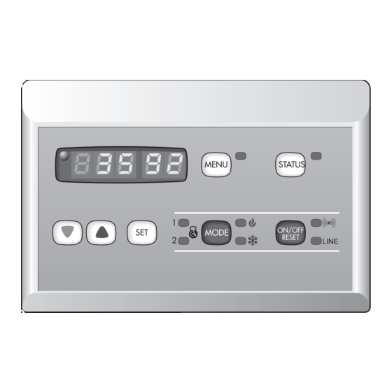
Page 4: Keypad
KEYPAD The keypad allows the following operations: - Select system operating mode - Display system status - Change unit operating parameters READING DISPLAY This is the 3-digit display on the left. The return water temperature is shown in degrees (default). The following can also be displayed: - Values of all parameters controlled by the equipment - Alarm codes... -
Page 5: Parameters, Status And Readings
PARAMETERS, STATUS AND READINGS WHAT IS A PARAMETER? A parameter is an internal program reference containing important values which can be set to allow the user or installer to ensure proper operation of the unit. HOW TO PROGRAM PARAMETERS - To program parameters, press the key. -
Page 6: Device Status Table
DEVICE STATUS TABLE WHAT IS A DEVICE? The system comprises various unit status. key enables the user to obtain a status list for the unit’s devices. This can be used to read the probe temperatures or the operating hours, for example. To access this list, press the key and then press the keys to display each device. -
Page 7: Alarm Codes
DEVICE STATUS TABLE Code or device Description Function number Pump hours --- Pump unavailable Displays number of hours since last reset If the top left LED is lit multiply the hours x 100 Low temperature resistance ---Resistances not present status 01 Resistances operating 06 Resistances not operating Not used... -
Page 8: Thermostat Function
THERMOSTAT FUNCTION The water temperature is thermostatically controlled via a set point and a tolerance range. The operation of these parameters is shown in the following diagram. COOLING MODE OPERATION Compressor ON Compressor OFF Set Point - 1/2 Differential Set Point + 1/2 Differential Set Point During the cooling mode the key readings are the following: PARAMETER 02. -
Page 9: Defrost System Description
DEFROST SYSTEM DESCRIPTION (HYDRON B and HYDRON BC UNITS) For the heat pump units, during the winter (heating) mode, the condenser converts the cooling system into an evaporator. Consequently, at low outside temperatures frost forms in inside it. The frost prevents the exchanger from operating efficiently. -
Page 10: Alarm And Low Water Temperature Device Description
CONDENSATION CONTROL SYSTEM DESCRIPTION Fan low threshold output This is the percentage of current which enters the fan control when the latter is rotating at min. speed. Fan high threshold output This is the percentage of current which enters the fan control when the latter is rotating at max. speed. Cooling fan set point cut-off If the temperature drops below this value even with the control, the fan will stop to prevent it from dropping excessively, starting when it drops below this value with a small tolerance range. -
Page 11: Notes
: + 31 33 2471 800 fax : + 31 33 2459 220 e-mail : info lennoxbenelux.com POLAND : LENNOX POLSKA SP z o.o. tél. : + 48 22 832 26 61 fax : + 48 22 832 26 62 e-mail : lennoxpolska inetia.pl PORTUGAL : LENNOX CLIMATIZAÇAO LDA.
Need help?
Do you have a question about the HYDRON Series and is the answer not in the manual?
Questions and answers