Table of Contents
Advertisement
Advertisement
Table of Contents

Related Manuals for Tenda 11AC


Summary of Contents for Tenda 11AC
- Page 1 11AC 1200Mbps Wireless In-wall Access Point User Guide...
- Page 2 Tenda reserves the right to make changes to the products without obligation to notify any person or organization of such revisions or changes. Tenda does not assume any liability that may occur due to the use or application of the product described herein. Every effort has been made in the preparation of this document to ensure accuracy of the contents, but all statements, information and recommendations in this document do not constitute the warranty of any kind, express or implied.
- Page 3 Preface Thank you for choosing Tenda! Please read this user guide before you start with W9 Conventions The typographical elements that may be found in this document are defined as follows. Item Presentation Example Cascading menus > System > Live Users...
- Page 4 For more information, search this product model on our website at http://www.Tendacn.com. Technical Support If you need more help, contact us by any of the following means. We will be glad to assist you as soon as possible. Canada: 1-888-998-8966 support@Tenda.cn Hong Kong: 00852-81931998 Hotline Email http://www.Tendacn.com...
-
Page 5: Table Of Contents
Application Scenarios ............................4 2.1 Large Apartment or Villa ..........................4 2.1.1 Deploying the AP with a Tenda Router with the AP Controller Functionality ........4 2.1.2 Deploying the AP with a Router of Another Brand ................5 2.2 Hotel ................................9 Login ................................ - Page 6 Wireless Settings .............................. 33 7.1 Basic Settings ............................. 33 7.1.1 Overview ............................33 7.1.2 Modifying SSID Settings ........................35 7.1.3 Examples of Configuring SSID Settings ................... 40 7.2 Radio Settings ............................60 7.2.1 Overview ............................60 7.2.2 Modifying Radio Settings ........................ 60 7.3 Radio Optimization ............................
- Page 7 9.2.2 Login Timeout Interval ........................88 9.3 Logs ................................89 9.3.1 Viewing Logs ........................... 89 9.3.2 Configuring Log Settings ......................... 89 9.4 Configuration ............................. 93 9.4.1 Backing Up and Restoring Configurations ..................93 9.4.2 Restoring the Factory Settings ......................95 9.5 Account ..............................
-
Page 8: Product Overview
1200 Mbps. It can be powered by IEEE 802.3af standard PoE switch and managed using its web UI or a Tenda wireless AP controller (or a Tenda router that supports the AP controller functionality). -
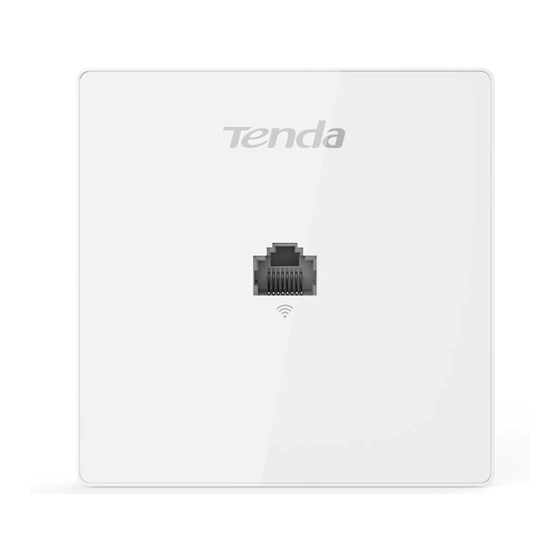
Page 9: Label
Reset Button It is visible after the front cover of the AP is removed. After the AP is powered on, you can use a paper clip to hold down this button for about 8 seconds to restore the factory settings. ... - Page 10 The label is described as follows: (1): Default IP address of the AP. You can use this IP address to log in to the web UI of the AP. (2): Default user name and password of the web UI of the AP.
-
Page 11: Application Scenarios
Controller Functionality For a large apartment or villa, you are recommended to adopt the Tenda wireless product solution, which includes a wired router (such as G3), a PoE switch (such as TEF1109P), and 4 to 8 W9. Deploy one W9 in each room and place the router and switch in an electronic junction box. -
Page 12: Deploying The Ap With A Router Of Another Brand
Start a web browser, enter the management IP address of the router to log in to the web UI of the router, and configure the APs. For details about how to configure the AP on the router web UI, refer to the user guide of the router. The user guide is available at http://www.Tenda.com.cn. 2.1.2 Deploying the AP with a Router of Another Brand The following describes the procedure. - Page 13 Double-click Internet Protocol Version 4 (TCP/IPv4), select Use the following IP address, set IP address to 192.168.0.X (X: 2 - 253) and Subnet mask to 255.255.255.0, and click OK. Step 3 Log in to the Web UI of the AP. Start a web browser, enter the management IP address of the AP (default: 192.168.0.254), and press Enter.
- Page 14 Enter the user name and password of the AP (default user name and password: admin) and click Login. Step 4 Set AP1. To access the page, click Quick Setup. Select the check box of AP Mode, enter an SSID (wireless network name), select WPA2-PSK from the dropdown list box of Security Mode, select the check box of AES as the Cipher Type, enter a security key (wireless network password, such as 12345678), and click Save.
- Page 15 Choose Network Settings > LAN Setup, change the IP address to an unused IP address that in the same network segment as those of the later connected APs, such as 192.168.0.201, and click Save. Step 5 Set the other APs. Perform step 3 and step 4 to connect the other APs to the PoE switch one by one and configure them.
-
Page 16: Hotel
Hotel A large number of APs need to be deployed in a hotel. You can use a Tenda wireless AP controller (such as M3) to configure and manage them centrally and efficiently. The following describes the procedure. Step 1 Connect the devices. -
Page 17: Login
Login Logging in to the Web UI of the AP You can log in to the web UI of the AP using a web browser. The procedure is as follows: Step 1 Use an Ethernet cable to connect the management computer to the AP or the switch connected to the AP. - Page 18 If the login page is not displayed, refer to in FAQ. ---End You can now start configuring the AP.
-
Page 19: Logging Out Of The Web Ui Of The Ap
Logging out of the Web UI of the AP If you log in to the web UI of the AP and perform no operation within the login timeout interval, the AP logs you out. When you close the web browser, the system logs you out as well. You can log out by clicking Logout in the upper-right corner. - Page 20 The functions and parameters dimmed on the web UI indicates that they are not supported by the AP or cannot be changed in the current configuration. Name Description ❶ 1-level navigation bar The navigation bars and tab pages display the function menu of the ❷...
-
Page 21: Common Buttons
Common Buttons The following table describes the common buttons available on the web UI of the AP. Button Description It is used to refresh the current page. It is used to save the configuration on the current page and enable the configuration to take effect. It is used to change the current configuration on the current page back to the original configuration. -
Page 22: Quick Setup
Quick Setup Overview This module enables you to quickly configure the AP so that wireless devices such as smart phones and tablets can access the internet through the wireless network of the AP. This AP can work in AP mode or Client+AP mode. ... - Page 23 Client+AP Mode In this mode, the AP is wirelessly bridged to an upstream device (such as a wireless router or AP) to extend the wireless network coverage of the upstream device. See the following topology. Internet PoE switch Router Client+AP Mode Upstream AP...
-
Page 24: Quick Setup
Quick Setup 4.2.1 AP Mode Before configuration, ensure that the upstream device has been connected to the internet. Step 1 Choose Quick Setup. Step 2 Select a radio band from the drop-down list box to be configured, which is 2.4 GHz in this example. Step 3 Keep the default configuration of working mode. -
Page 25: Client+Ap Mode
Parameter description Parameter Description Radio Band It specifies the radio band of the WiFi network to be configured. Working Mode It specifies the working mode of the AP, including AP mode and Client+AP mode. SSID It specifies the primary SSID (wireless network name) of the AP. It specifies the security mode of the wireless network of the AP. - Page 26 Step 5 Select the wireless network to be extended from the wireless network list that appears. If no wireless network is found, choose Wireless Settings > Radio Settings, ensure that Enable Wireless is selected, and try scanning wireless network again. After a wireless network to be extended is selected, the SSID, security mode, and channel of the wireless network ...
- Page 27 Parameter Description Parameter Description Radio Band It specifies the radio band of the WiFi network to be configured. It specifies the working mode of the AP, including AP mode and Client+AP mode. AP mode: In this mode, wireless clients can connect to this device, but this device cannot connect Working Mode to peers.
-
Page 28: Status
Status This module allows you to view system status, wireless status, traffic statistics wireless clients. System Status To access the page, choose Status > System Status. The page displays the system and LAN port status of the AP. Parameter description Parameter Description It specifies the name of the AP. - Page 29 Parameter Description It specifies the physical address of the LAN port of the AP. If you connect the AP to other devices MAC Address using Ethernet cables, the AP uses this MAC address to communicate with those devices. It specifies the IP address of the AP. IP Address The web UI of the AP is accessible at this IP address.
-
Page 30: Wireless Status
Wireless Status The access the page, choose Status > Wireless Status. This page displays general radio status and SSID status of the AP. By default, the page displays the information of 2.4 GHz wireless status. To view the wireless status of 5 GHz, click 5 GHz Wireless Status. Parameter description Parameter Description... -
Page 31: Traffic Statistics
Traffic Statistics To access the page, choose Status > Traffic Statistics. This page displays the statistics about historical packets of the wireless networks of the AP. By default the page displays the traffic statistics information of 2.4 GHz. To view information about 5 GHz, click 5 GHz Traffic Statistics. -
Page 32: Wireless Clients
Wireless Clients To access the page, choose Status > Wireless Clients. This page displays information about the wireless clients connected to the wireless networks corresponding to the SSIDs of the AP. By default, the page displays information about the wireless clients connected to the 2.4 GHz wireless network corresponding to the primary SSID of the AP. -
Page 33: Network Settings
Network Settings LAN Setup To access the page, choose Network Settings > LAN Setup. This page enables you to view the MAC address of the LAN port of the AP and set the name, Ethernet Mode, IP obtaining method, and other related parameters of the AP. Parameter description Parameter Description... -
Page 34: Modifying The Lan Ip Address Of The Ap
Parameter Description server. It specifies the IP address of the AP. The web UI of the AP is accessible at this IP address. The default IP address is 192.168.0.254. IP Address Generally, ensure that this IP address is in the same network segment as the LAN IP address of your LAN router connected to the internet, so that the AP can access the internet. - Page 35 Step 3 Set IP Address, Subnet Mask, Default Gateway, and Primary DNS Server. If another DNS server is available, set Secondary DNS Server to the IP address of the additional DNS server. Step 4 Click Save. Step 5 Click OK. ---End The following page is displayed.
- Page 36 Automatically Obtaining an IP Address This mode enables the AP to automatically obtain an IP address, a subnet mask, a gateway IP address, DNS server IP addresses from a DHCP server on your LAN. If a large number of APs are deployed, you can adopt this mode to avoid IP address conflicts and effectively reduce your workload.
-
Page 37: Dhcp Server
DHCP Server 6.2.1 Overview The AP provides a DHCP server function to assign IP addresses to clients on the LAN. By default, the DHCP server function is disabled. If the new and original IP addresses of the LAN port belong to different network segment, the system changes the IP address pool of the DHCP server function of the AP so that the IP address pool and the new IP address of the LAN port belong to the same network segment. - Page 38 Parameter description Parameter Description DHCP Server It specifies whether to enable the DHCP server function of the AP. By default, it is disabled. It specifies the start IP address of the IP address pool of the DHCP server. The default value is Start IP Address 192.168.0.100.
-
Page 39: Viewing The Dhcp Client List
6.2.3 Viewing the DHCP Client List If the AP functions as a DHCP server, you can view the DHCP client list to understand the details about the clients that obtain IP addresses from the DHCP server. The details include host names, IP addresses, MAC addresses, and lease times. -
Page 40: Wireless Settings
Wireless Settings Basic Settings 7.1.1 Overview This module enables you to set SSID-related parameters of the AP. Broadcast SSID When the AP broadcasts an SSID, nearby wireless clients can detect the SSID. When this parameter is set to Disable, the AP does not broadcast the SSID and nearby wireless clients cannot detect the SSID. In this case, you need to enter the SSID manually on your wireless client if you want to connect to the wireless network corresponding to the SSID. - Page 41 Max. Number of Clients This parameter specifies the maximum number of clients that can connect to the wireless network corresponding to an SSID. If the number is reached, the wireless network rejects new connection requests from clients. This limit helps balance load among APs. Security Mode A wireless network uses radio, which is open to the public, as its data transmission medium.
-
Page 42: Modifying Ssid Settings
7.1.2 Modifying SSID Settings To change the related settings of an SSID, perform the following procedure: Step 1 Choose Wireless Setting> SSID Settings. Step 2 Click the tab to choose the radio band to be set. Step 3 Change the parameters as required. Generally, you only need to change the Enable, SSID, and Security Mode settings. - Page 43 Parameter Description enter the SSID on the client. This AP can automatically hide its SSID. When the number of clients connected to the AP with an SSID of the AP reaches the upper limit, the AP stops broadcasting the SSID. ...
- Page 44 Parameter description Parameter Description It specifies the authentication type for the WEP security mode. The options include Open, Shared, and 802.1x.The options share the same encryption process. Open: It specifies that authentication is not required and data exchanged is encrypted using WEP. In this case, a wireless client can connect to the wireless network corresponding to the selected SSID without being authenticated, and the data exchanged between the client and the network is encrypted in WEP security mode.
- Page 45 WPA-PSK, WPA2-PSK, and Mixed WPA/WPA2-PSK Parameter description Parameter Description It indicates the personal or pre-shared key security mode, including WPA-PSK, WPA2-PSK, and Mixed WPA/WPA2-PSK. WPA-PSK: It indicates that the wireless network corresponding to the selected SSID is encrypted using WPA-PSK.
- Page 46 WPA and WPA2 Parameter description Parameter Description The WPA and WPA2 options are available for network protection with a RADIUS server. WPA: It indicates that the wireless network corresponding to the selected SSID is encrypted using Security Mode WPA.
-
Page 47: Examples Of Configuring Ssid Settings
7.1.3 Examples of Configuring SSID Settings Setting up a Non-encrypted Wireless Network Networking requirement In a hotel lounge, guests can connect to the wireless network without a password and access the internet through the WiFi network. Internet PoE switch Router SSID: FREE Configuration procedure Assume that the second SSID of the AP, the WPA2-PSK security mode, and AES encryption algorithm are used. - Page 48 ---End Verification Verify that wireless devices can connect to the FREE wireless network without a password.
- Page 49 Setting up a Wireless Network Encrypted Using WPA/WPA2-PSK Networking requirement A home wireless network with a certain level of security must be set up through a simply procedure. In this case, WPA/WPA2 pre-shared key mode is recommended. See the following figure. Internet Router PoE switch...
- Page 50 ---End Verification Verify that wireless devices can connect to the Home wireless network with the password 87654321.
- Page 51 Setting up a Wireless Network Encrypted Using WPA or WPA2 Networking requirement A highly secure wireless network is required and a RADIUS server is available. In this case, WPA or WPA2 pre-shared key mode is recommended. See the following figure. Internet RADIUS server IP: 192.168.0.200...
- Page 52 ---End Configure the RADIUS server Windows 2003 is used as an example to describe how to configure the RADIUS server. Step 1 Configure a RADIUS client.
- Page 53 In the Computer Management dialog box, double-click Internet Authentication Service, right-click RADIUS Clients, and choose New RADIUS Client. Enter a RADIUS client name (which can be the name of the AP) and the IP address of the AP, and click Next.
- Page 54 Enter 12345678 in the Shared secret and Confirm shared secret text boxes, and click Finish. Password same as that specified by RADIUS Password on the AP. Step 2 Configure a remote access policy. Right-click Remote Access Policies and choose New Remote Access Policy.
- Page 55 In the New Remote Access Policy Wizard dialog box that appears, click Next. Enter a policy name and click Next.
- Page 56 Select Ethernet and click Next. Select Group and click Add.
- Page 57 Enter 802.1x in the Enter the object names to select text box, click Check Names, and click OK. Select Protected EAP (PEAP) and click Next.
- Page 58 Click Finish. The remote access policy is created. Right-click root and choose Properties. Select Grant remote access permission, select NAS-Port-Type matches "Ethernet" AND, and click Edit.
- Page 59 Select Wireless – Other, click Add, and click OK. Click Edit Profile, click the Authentication tab, configure settings as shown in the following figure, and click OK. When a message appears, click No. Step 3 Configure user information. Create a user and add the user to group 802.1x. ---End...
- Page 60 Configure your wireless device Windows 7 is taken as an example to describe the procedure. Step 1 Choose Start > Control Panel, click Network and Internet, click Network and Sharing Center, and click Manage wireless networks. Step 2 Click Add.
- Page 61 Step 3 Click Manually create a network profile. Step 4 Enter wireless network information, select Connect even if the network is not broadcasting, and click Next. Same as the security mode of the SSID of the AP...
- Page 62 Step 5 Click Change connection settings. Step 6 Click the Security tab, select Microsoft: Protected EAP (PEAP), and click Settings.
- Page 63 Step 7 Deselect Validate server certificate and click Configure. Step 8 Deselect Automatically use my Windows logon name and password (and domain if any) and click...
- Page 64 Step 9 Click Advanced settings. Step 10 Select User or computer authentication and click OK.
- Page 65 Step 11 Click Close.
- Page 66 Step 12 Click the network icon in the lower-right corner of the desktop and choose the wireless network of the AP, such as hot_spot in this example. Step 13 In the Windows Security dialog box that appears, enter the user name and password set on the RADIUS server and click OK.
-
Page 67: Radio Settings
Radio Settings 7.2.1 Overview This module is used to set Radio parameters of the AP. The following briefly describes the SSID isolation function. SSID isolation This function isolates the wireless clients connected to different wireless networks of the AP. For example, if user 1 connects to the wireless network corresponding to SSID1, whereas user 2 connects to the wireless network corresponding to SSID2, the two users cannot communicate with each other after SSID isolation is implemented. - Page 68 11a: The AP works in 802.11a mode and only wireless devices compliant with 802.11a can connect to the 5 GHz wireless networks of the AP. 11ac: The AP works in 802.11ac mode and only wireless devices compliant with 802.11ac can connect to the 5 GHz wireless networks of the AP. ...
- Page 69 It specifies the wireless channel bandwidth of the AP. This parameter can be set if the AP works in 802.11 b/g/n, 802.11ac, 802.11a/n mode and Channel Lockout is not selected. 20 MHz: It indicates that the AP can use only 20 MHz channel bandwidth.
-
Page 70: Radio Optimization
Radio Optimization 7.3.1 Overview Application Scenarios Generally, wireless networks are widely applied to the following two scenarios: Ordinary scenario For areas that demand wide WiFi coverage, such as offices, public buildings, schools, warehouses and hospitals. High density scenario For large crowded areas, such as: Conference halls, theaters, exhibition and banquet halls −... -
Page 71: Optimizing Radio
Disable Prioritize 5 GHz Enable Prioritize 5 GHz 2.4 GHz 5 GHz 2.4 GHz 5 GHz Dual-band clients to Dual-band clients to Dual-band clients to 5 Dual-band clients 5 GHz 2.4 GHz to 2.4 GHz * Assume that the max. number of clients allowed to connect to the 5 GHz is10. - Page 72 ---End Parameter description Parameter Description Used to set the interval at which this device sends Beacon frames. Beacon frames are sent at the interval to announce the existence of a wireless network. Generally, a Beacon Interval smaller interval allows wireless clients to connect to this device sooner, while a larger interval allows the wireless network to transmit data quicker.
- Page 73 Parameter Description interval. Minimum strength of received signals acceptable to this device. If the strength of the signals transmitted by a wireless device is weaker than this threshold, the wireless device cannot connect to Minimum RSSI this device. Threshold A proper value facilitates wireless devices to connect to the AP with stronger signal in case of multiple APs exist.
-
Page 74: Wmm Settings
WMM Settings 7.4.1 Overview 802.11 networks offer wireless access services based on the Carrier Sense Multiple Access with Collision Avoidance (CSMA/CA) channel competition mechanism, which allows all wireless clients to fairly compete for channels. All the services implemented over wireless networks share the same channel competition parameters. -
Page 75: Modidying Wmm Settings
ACK Policies WMM specifies the Normal ACK and No ACK policies. According to the No ACK policy, no ACK packet is used during wireless packet transmission to − acknowledge packet reception. This policy is applicable to scenarios where interference is mild and can effectively improve transmission efficiency. - Page 76 ---End Parameter description Parameter Description Enable: It is used to enable the WMM function. WMM Settings Disable: It is used to disable the WMM function. It specifies the WMM optimization modes supported by the AP: Optimized For scenario with 1 - 10 users: If 10 or less clients are connected to the AP, you are recommended to select this mode to obtain higher client throughput.
-
Page 77: Access Control
Access Control 7.5.1 Overview The access control function enables you to allow or disallow the wireless devices to access the wireless network of the AP based on their MAC addresses. The AP supports the following 3 filter modes: Disable: It indicates that access control is disabled. In this case, all wireless devices can access the −... - Page 78 Wireless client list Wireless access control list Parameter description Parameter Description SSID It specifies the wireless network to which the rule applies. It specifies the filter mode of the rule. Disable: It indicates that the access control function is disabled. ...
-
Page 79: Example Of Configuring Access Control
7.5.3 Example of Configuring Access Control Networking requirement A wireless network whose SSID is Home has been set up in a large apartment. Only family members are allowed to connect to the wireless network. The Access Control function of the AP is recommended. The family members have three wireless devices whose MAC addresses are C8:3A:35:00:00:01, C8:3A:35:00:00:02, and C8:3A:35:00:00:03. -
Page 80: Advanced Settings
Advanced Settings 7.6.1 Overview This module is used to set the Identify Client Type and Broadcast Packet Filter of the AP. Identify Client Type It specifies whether to identify operating system types of wireless clients connected to this device. Terminal types that the AP can identify include: Android, iOS, WPhone, Windows, Mac OS, and so on. - Page 81 Parameter Description Disable: It specifies whether to disable the function. Select a mode after you enable the broadcast packet filter function. Accept only DHCP and ARP packets: Filter out all broadcast or multicast data except DHCP and Filter Mode ARP packets.
-
Page 82: Qvlan Settings
QVLAN Settings 7.7.1 Overview The AP supports 802.1Q VLANs and is applicable in a network environment where 802.1Q VLANs have been defined. By default, the QVLAN function is disabled. 7.7.2 Configuring the QVLAN Function Step 1 Choose Wireless Setting > QVLAN Settings. Step 2 Change the parameters as required. -
Page 83: Example Of Configuring Qvlan Settings
Parameter Description If the QVLAN function is enabled, at least one LAN port needs to be set as a trunk port. LAN0 indicates the LAN port at the rear of the AP (PoE power supply, data transmission multiplexing port), whereas LAN1 indicates the LAN port (data transmission port) at the front of the AP. LAN Port It specifies the LAN ports of the AP, including LAN0 and LAN1. - Page 84 Networking assumption Set the SSID to internet for guests, oa for staffs, and VIP for managers for 2.4 GHz network. − The wireless networks with the aforementioned SSIDs are enabled and set on the AP. − Network topology Internet Internal server PoE switch Router LAN0...
- Page 85 ---End Wait for the automatic reboot of the AP. Configure the switch Create IEEE 802.1Q VLANs described in the following table on the switch. Port Connected To Accessible VLAN ID Port Type PVID 1,2,3,4 Trunk LAN server Trunk Router Trunk Retain the default settings of other ports.
-
Page 86: Snmp
SNMP Overview The Simple Network Management Protocol (SNMP) is the most widely used network management protocol in TCP/IP networks. SNMP enables you to remotely manage all your network devices compliant with this protocol, such as monitoring the network status, changing network device settings, and receive network event alarms. SNMP allows automatic management of devices from various vendors regardless of physical differences among the devices. -
Page 87: Snmp Protocol Version
8.1.3 SNMP Protocol Version The AP is compatible with SNMP V1 and SNMP V2C and adopts the community authentication mechanism. Community name is used to define the relationship between an SNMP agent and an SNMP manager. If the community name contained in an SNMP packet is rejected by a device, the packet is discarded. A community name functions as a password to control SNMP agent access attempts of SNMP managers. -
Page 88: Configuring The Snmp Function
Configuring the SNMP Function Step 1 Choose SNMP and set SNMP Agent to Enable. Step 2 Set related SNMP parameters. Step 3 Click Save. ---End Parameter description Parameter Description It specifies whether to enable the SNMP agent function of the AP. By default, it is disabled. An SNMP manager and the SNMP agent can communicate with each other only if their SNMP SNMP Agent versions are the same. -
Page 89: Example Of Configuring The Snmp Function
Parameter Description The SNMP agent function of the AP allows an SNMP manager to use the password to read/write variables in the MIB of the AP. Example of Configuring the SNMP Function Networking requirement The AP connects to an NMS over an LAN. This IP address of the AP is 192.168.0.254/24 and the IP −... - Page 90 ---End Configuring the NMS On an NMS that uses SNMP V1 or SNMP V2C, set the read community to Tom and read/write community to Tom 123. For details about how to configure the NMS, refer to the configuration guide for the NMS. Verification After the configuration, the NMS can connect to the SNMP agent of the AP and query and set some parameters on the SNMP agent through the MIB.
-
Page 91: Tools
AP connected during an upgrade. Configuration procedure: Step 1 Download the package of a later firmware version for the AP from http://www.Tenda.com.cn to your local computer, and decompress the package. Step 2 Log in to the web UI of the AP and choose Tools >... - Page 92 After the firmware is upgraded, you are recommended to restore the factory settings of the AP and configure the AP again, so as to ensure stability of the AP and proper operation of new functions.
-
Page 93: Date & Time
Date & Time This module enables you to set the system time login timeout interval of the AP. 9.2.1 System Time Ensure that the system time of the AP is correct, so that logs can be recorded correctly and the reboot schedule can be executed correctly. - Page 94 Step 5 Click Save. ---End Setting Time and Date Manually You can manually set the system time of the AP. If you choose this option, you need to set the system time each time after the AP reboots. Configuration procedure: Step 1 Choose Tools >...
-
Page 95: Login Timeout Interval
9.2.2 Login Timeout Interval If you log in to the web UI of the AP and perform no operation within the login timeout interval, the AP logs you out for network security. The default login timeout interval is 5 minutes. Procedure for setting the login timeout interval: Choose Tools >... -
Page 96: Logs
Logs This module enables you to view logs configure log settings. 9.3.1 Viewing Logs The logs of the AP record various events that occur and the operations that users perform after the AP starts. In case of a system fault, you can refer to the logs during troubleshooting. To access the page, choose Tools >... - Page 97 Setting the Number of Logs to Be Displayed By default, the AP can display a maximum of 150 logs on the View Logs page. You can change the number as required. Configuration procedure: Step 1 To access the page, choose Tools > Logs and click Log Settings. Step 2 Change the number of logs as required within the range of 100 to 300.
- Page 98 Step 3 Set parameters as follows: Set Log Server IP Address to the IP address of the log server. Set Log Server Port to the UDP port number used to send and receive system logs. The default port number 514 is recommended. Select Enable to enable the log server.
- Page 99 ---End Procedure for deleting log server settings Step 1 To access the page, choose Tools > Logs and click Log Settings. Step 2 Click Delete corresponding to the log server settings to be deleted. Step 3 Click OK. ---End...
-
Page 100: Configuration
Configuration This module enables you to back up the current configuration of the restore a configuration of the AP, and restore the factory settings of the 9.4.1 Backing Up and Restoring Configurations The backup function enables you to back up the current configuration of the AP to a local computer. The restoration function enables you to restore the AP to a previous configuration. - Page 101 Step 3 Click OK. ---End A configuration file named APCfm.cfg is downloaded. Restoring a Configuration Step 1 Choose Tools > Configuration > Backup & Restore. Step 2 Click Choose File and select the file of the configuration to be restored. Step 3 Click Restore and follow the on-screen instructions to perform operations.
-
Page 102: Restoring The Factory Settings
9.4.2 Restoring the Factory Settings If you cannot locate a fault of the AP or forget the password of the web UI of the AP, you can reset the AP to restore its factory settings and then configure it again. ... - Page 103 Method 2: Step 1 Log in to the web UI of the AP, choose Tools > Configuration and click the Reset tab. Step 2 Click the Reset button. Step 3 Click OK. ---End Wait until the progress bar is done.
-
Page 104: Account
Account To access page for changing user names and passwords, choose Tools > Account. On this page, you can change the login account information of the AP to prevent unauthorized login. Parameter description Parameter Description Administrator: An account of this type enables you to view and modify settings of the AP. Account Type ... -
Page 105: Diagnostics Tool
Diagnostics Tool If the network connection fails, you can use the diagnostics tool included with the AP to locate the faulty node. Procedure: The link to www.google.com is used as an example. Step 1 Choose Tools > Diagnostics Tool. Step 2 Enter the IP address or domain name to be pinged in the IP Address/Domain Name text box. -
Page 107: Reboot Device
Reboot Device This module enables you to manually reboot the AP or configure the AP to automatically reboot. When the AP reboots, all connections are released. You are recommended to reboot the AP at an idle hour. 9.7.1 Manual Reboot If a setting does not take effect or the AP works improperly, you can try rebooting the AP manually to resolve the problem. -
Page 108: Reboot Schedule
9.7.2 Reboot Schedule This function enables the AP to automatically reboot as scheduled. You can use this function to prevent wireless performance degradation or network instability that occurs after a long AP uptime. The AP can reboot: At intervals: In this mode, the AP reboots at the interval that you specify. −... - Page 109 ---End...
-
Page 110: Led Control
LED Control This function enables you to turn on/off the LED indicator of the AP. By default, the LED indicator is turned on. Procedure for turning off the LED indicator: Step 1 Choose Tools > LED Control. Step 2 Click Disable all LEDs. ---End Procedure for turning on the LED indicator: Step 1... -
Page 111: Uplink Check
Uplink Check 9.9.1 Overview In AP mode, the AP connects to its upstream network using the LAN0 port. If a critical node between the LAN0 port and the upstream network fails, the AP as well as the wireless clients connected to the AP cannot access the upstream network. - Page 112 ---End...
-
Page 113: Appendixes
2-253).Ensure the IP address of the AP (it is 192.168.0.254 by default) is entered in the browser address bar (not search bar). If two or more APs are connected to your network without a Tenda AP controller (including a −... -
Page 114: Default Parameter Values
Default Parameter Values The following table lists the default parameter values of the AP. Parameter Default Value Management IP address 192.168.0.254 Login Administrator admin|admin User Name/Password User user|user Quick Setup Working Mode AP Mode IP Address Type Static IP Address IP Address 192.168.0.254 Subnet Mask... - Page 115 Max. Number of Clients Chinese SSID Encoding UTF-8 Security Mode None Enable wireless Enable Country/Region China 2.4GHz 11b/g/n Network Mode 5GHz 11ac Channel Auto 2.4GHz 20/40 MHz Channel Radio Settings Bandwidth 5GHz 80 MHz Lock Channel Enable Lock Power Enable...
- Page 116 Parameter Default Value DTIM Interval Minimum RSSI Threshold -90 dBm Prioritize 5GHz Disable Air Interface Scheduling Disable APSD Disable Client Timeout Interval 5 minutes 2.4 GHz 1, 2, 5.5, 11 Mandatory Rate 5 GHz 6, 12, 24 2.4 GHz 1, 2, 5.5, 6, 9, 11, 12, 18, 24, 36, 48, 54 Optional Rate 5 GHz 6, 9, 12, 18, 24, 36, 48, 54...
- Page 117 Parameter Default Value Read/Write Community private If Synchronize with Internet time is selected: System Time Time Zone: (GMT+08:00) Beijing, Chongqing, Hong Kong, Urumqi, Taipei Time & Date Login Timeout 5 minutes Interval Number of Logs Displayed Tools Log server settings None Reboot Schedule Disable...
Need help?
Do you have a question about the 11AC and is the answer not in the manual?
Questions and answers