Page 3
(both customer and service) only. If you need to include such a block in your manual, please submit a request to Illustration and provide a sample for setting up copy. EMC Connectrix B DS-5000B Hardware Reference Manual...
Page 4
EMC Connectrix B DS-5000B Hardware Reference Manual...
Correcting the time zone of a switch ........32 Recommendations for cable management ........34 Chapter 3 Monitoring System Compenents Powering the DS-5000B on and off..........36 Interpreting LED activity..............36 Interpreting POST results ..............40 EMC Connectrix B DS-5000B Hardware Reference Manual...
Page 6
Fibre Channel port specifications ..........60 Serial port specifications ..............61 POST and Boot specifications ............62 POST.................... 62 Boot....................62 Regulatory compliance ..............63 Environmental regulation compliance ......... 67 Index ..........................71 EMC Connectrix B DS-5000B Hardware Reference Manual...
Preface As part of an effort to improve and enhance the performance and capabilities of its product lines, EMC periodically releases revisions of its hardware and software. Therefore, some functions described in this document may not be supported by all versions of the software or hardware currently in use. For the most up-to-date information on product features, refer to your product release notes.
Page 8
Preface Conventions used in EMC uses the following conventions for special notices. this document Note: A note presents information that is important, but not hazard-related. CAUTION A caution contains information essential to avoid data loss or damage to the system or equipment. The caution may apply to hardware or software.
Page 9
Preface Typographical EMC uses the following type style conventions in this document: conventions Normal Used in running (nonprocedural) text for: • Names of interface elements (such as names of windows, dialog boxes, buttons, fields, and menus) • Names of resources, attributes, pools, Boolean expressions,...
Page 10
Technical support — For technical support, go to EMC Customer Service on Powerlink. To open a service request through Powerlink, you must have a valid support agreement. Please contact your EMC sales representative for details about obtaining a valid support agreement or to answer any questions about your account.
Invisible Body Tag Overview This chapter includes the following sections: Overview of the DS-5000B..............12 ◆ Managing the DS-5000B ..............15 ◆ Supported features................16 ◆ Overview...
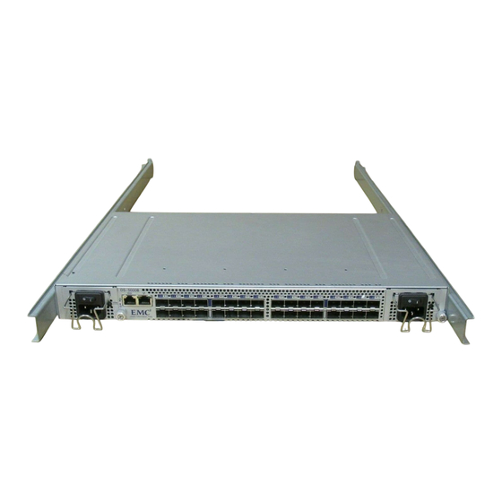
Channel SFP ports that supports link speeds up to 1, 2, or 4 Gbit/sec. It includes the Fabric Operating System and is compatible with the entire EMC Connectrix B product family. The DS-5000B can operate in a fabric containing multiple switches or independently.
Page 13
Overview The DS-5000B can be mounted in a 1U 19-inch Electronic Industries Association (EIA) rack, with a height of 1U. Because of the shallow depth, no rail kits are required for a rack mount, however the switch can be installed using the optional rack mount kit. The DS-5000B can also be used in a tabletop configuration.
Note: ISL Trunking is an optionally licensed software that allows you to create trunking groups of ISLs between adjacent switches. For more information about ISL Trunking, refer to the EMC Connectrix B Series Fabric OS Administrator’s Guide. The port side of the DS-5000B switch also displays the system status...
Guide and the EMC Connectrix B Series Fabric OS Command Reference Manual. Web Tools Ethernet or serial IP over Fibre Channel connection For information, refer to the EMC Connectrix B Series Web Tools Administrator’s Guide. Standard SNMP applications Ethernet or serial IP over Fibre Channel connection For information, refer to the EMC Connectrix B Series MIIB Reference Manual.
ISL Trunking ◆ Ports on Demand (1 and 2) ◆ For information on these features, refer to the EMC Connectrix B Fabric OS Administrator’s Guide. Ports On Demand The DS-5000B has 32 ports. By default, ports 0-15 are enabled. To enable additional ports, you must install Ports On Demand (POD) licenses.
Invisible Body Tag Installation and Configuration This chapter contains the following sections: Items included with the DS-5000B ..........18 ◆ Installation and safety considerations ..........19 ◆ Attaching mounting ears to the DS-5000B switch......21 ◆ Setting up the switch as a standalone unit ........24 ◆...
• Rubber mounting feet (to be used when setting up the DS-5000B as a standalone unit) • Two grounded 6-ft. (approximately 1.83 meters) country-specific power cords • One serial cable, 10-ft. (approximately 3 meters) long EMC Connectrix B DS-5000B Hardware Reference Manual...
Installation and Configuration Installation and safety considerations You can install the DS-5000B in the following four ways: In an EIA cabinet using the mounting ears provided with the ◆ switch. This is the recommended installation method. For instructions and more information, refer to “Installing the DS-5000B switch (with mounting ears attached) in a standard rack”...
Page 20
Verify that the additional weight of the switch does not exceed the ◆ cabinet’s weight limits or unbalance the cabinet in any way. Secure the cabinet to ensure stability in case of unexpected ◆ movement. EMC Connectrix B DS-5000B Hardware Reference Manual...
Installation and Configuration Attaching mounting ears to the DS-5000B switch The DS-5000B is shipped with mounting ears available in the accessory kit. To install or replace the mounting ears, follow the instructions in this section. Time and items Attaching or removing the mounting ears on the DS-5000B should required take only a couple of minutes.
Page 22
3. Using three of the screws provided and a screwdriver, attach the mounting ear to the switch. 4. Repeat steps 1 through 3 for the mounting ear marked “R” for right on the right side of the switch. EMC Connectrix B DS-5000B Hardware Reference Manual...
Installation and Configuration Installing the DS-5000B switch (with mounting ears attached) in a standard rack The DS-5000B can be installed in a standard EIA rack using the mounting ears. Time and items Installing the DS-5000B switch in an EIA rack using the mounting required ears should take about five minutes.
2. Clean the four corner depressions on the bottom of the switch and place a rubber foot in each one. This helps prevent the switch from accidentally sliding off the supporting surface. 3. Place the switch on a stable, flat surface. EMC Connectrix B DS-5000B Hardware Reference Manual...
Installation and Configuration Configuring the DS-5000B The DS-5000B must be configured correctly before it can operate within a network and fabric. The following items are required for configuring and connecting the DS-5000B for use in a network and fabric: The DS-5000B, installed and connected to a power source ◆...
Page 26
• In a Windows 95, 98, 2000, or NT environment: Bits per second:9600 Databits: 8 Parity: None Stop bits: 1 Flow control: None • In a UNIX environment, enter the following string at the prompt: tip /dev/ttyyb -9600 EMC Connectrix B DS-5000B Hardware Reference Manual...
Page 27
Installation and Configuration Connecting to the switch using the serial connection To log in to the switch through the serial connection: 1. Verify that the switch has completed POST. When POST is complete, the port status and switch power and status LEDs return to a standard healthy state;...
Page 28
At this point, the switch can be accessed remotely, by command line or Note: by Web Tools. Ensure that the switch is not being modified from any other connections during the remaining tasks. EMC Connectrix B DS-5000B Hardware Reference Manual...
Page 29
Installation and Configuration Completing switch configuration To complete the switch configuration: 1. Log on to the switch by telnet. 2. Modify the domain ID if required. The default domain ID is 1. If the switch is not powered on until after it is connected to the fabric and the default domain ID is already in use, the domain ID for the new switch is automatically reset to a unique value.
Page 30
Repeat Steps a and b for the remaining ports, as required. 5. Connect the cables to the transceivers. The cables used in trunking groups must meet specific requirements. For a list of these requirements, refer to the EMC Connectrix B Fabric OS Administrator’s Guide. CAUTION A 50-micron cable should not be bent to a radius less than 2 inches under full tensile load and 1.2 inches with no tensile load.
Installation and Configuration This command provides information about switch and port status. 8. Verify the correct operation of the DS-5000B in the fabric by typing the fabricShow command from the workstation. This command provides general information about the fabric. 9. Back up the switch configuration to an FTP server by typing the configUpload command and following the prompts.
1. Log in as admin. 2. Enter the tsTimeZone - - interactive command. 3. Follow the prompts to select the correct time zone for the switch. EMC Connectrix B DS-5000B Hardware Reference Manual...
Page 33
Installation and Configuration Refer to the tsTimeZone command in the Fabric OS Command Reference Manual for more detailed information about the command parameters. 4. Repeat steps 1 through 3 on all switches for which the time zone needs to be set. This needs to be done only once, because the value is stored in nonvolatile memory.
• For easier maintenance, label the fiber-optic cables and record the devices to which they are connected. • Keep LEDs visible by routing port andother cables directly down or otherwise away from the LEDs. EMC Connectrix B DS-5000B Hardware Reference Manual...
Invisible Body Tag Monitoring System Compenents This chapter includes the following sections: Powering the DS-5000B on and off..........36 ◆ Interpreting LED activity ..............36 ◆ Interpreting POST results ..............40 ◆ Maintaining the DS-5000B ..............41 ◆ Monitoring System Compenents...
One power status LED (below) on the left side ◆ 32 port status LEDs, one for each Fibre Channel port, located ◆ above the ports One power supply status LED on each power supply FRU, in the ◆ upper right corner EMC Connectrix B DS-5000B Hardware Reference Manual...
Page 37
Monitoring System Compenents Figure 4 shows the locations of the LEDs on the DS-5000B. Figure 4 LEDs on port side of DS-5000B System status LED Ethernet status LEDs (link left/speed right) Power supply status LED System power LED Port status LEDs Interpreting LED activity...
Page 38
No light There is no link. Verify that the Ethernet cable is connected correctly. Steady amber There is a link. No action required. Flashing amber/no There is link activity (traffic). No action required. light EMC Connectrix B DS-5000B Hardware Reference Manual...
Page 39
Check the management interface and (flashing in the error log for details on the cause of half-second status. intervals) Contact your EMC Customer Service Representative if required. Steady amber (for Port is receiving light or signal carrier at No action required. more than five 4 Gbit/sec;...
Any errors detected during POST are written to the system log, which is accessible through the errShow command. For information about this command, refer to the Fabric OS Command Reference. For information about error messages, refer to the System Message Reference . EMC Connectrix B DS-5000B Hardware Reference Manual...
Diagnostic tests might temporarily lock the transmit and receive speed Note: of the links during diagnostic testing. For information about specific diagnostic tests, refer to the EMC Connectrix B Fabric OS Administrator’s Guide. Field Replaceable Units (FRUs) Power Supply/Fan assembly replacement should be performed by an EMC Customer Service Representative.
Page 42
LED). If the system status LED is flashing amber and green, it could mean the fan has failed. Check the management interface and the error log for details on the cause of status. EMC Connectrix B DS-5000B Hardware Reference Manual...
Page 43
Monitoring System Compenents In Web Tools, check the Fan Status icon background color. It will ◆ be either yellow or red if the fan has failed. When the fan is functioning correctly, the background color is green. Type the fanShow command at the command prompt to display ◆...
Page 44
Monitoring System Compenents EMC Connectrix B DS-5000B Hardware Reference Manual...
Invisible Body Tag Remove and Replace System Components This chapter includes the following sections: Installing a power supply/fan assembly........46 ◆ Remove and Replace System Components...
5. The Fabric OS identifies the power supplies from left to right on the port side as PS1 (on the left) and PS2 (on the right). DS-5000B power supply/fan assembly unit Figure 5 EMC Connectrix B DS-5000B Hardware Reference Manual...
Page 47
Remove and Replace System Components Power supply/fan/assembly unit AC power switch Status LED Captive screw Power cord plug receptacle Power cord retainer CAUTION Disassembling any part of the power supply voids the part warranty and regulatory certifications. There are no user-serviceable parts inside the power supply.
1. If the switch is to continue operating during the replacement, verify that the other power supply/fan assembly unit (the one not being replaced) has been powered on for at least four seconds and has a green LED. EMC Connectrix B DS-5000B Hardware Reference Manual...
Page 49
Remove and Replace System Components 2. If the power supply/fan assembly unit you are replacing is not already off, press the AC power switch to “O” to power it off. Refer to Figure 5 on page 46 for the location of the AC power switch.
Page 50
The Fabric OS identifies the power supply/fan assembly unit in a DS-5000B from left to right as PS1 and PS2, when viewing the switch from the port side (see Figure EMC Connectrix B DS-5000B Hardware Reference Manual...
Page 51
Invisible Body Tag Specifications This appendix includes the following sections: Switch components................52 ◆ Weight and physical dimensions ............. 53 ◆ Facility requirements ................. 54 ◆ Power supply specifications............. 55 ◆ Environmental requirements............56 ◆ General specifications................ 57 ◆ Data transmission ranges..............58 ◆...
32 port LEDs, 1 switch power LED, 1 switch status LED, 2 ◆ Ethernet LEDs, and 2 power supply LEDs. Two universal AC input and redundant power supplies with AC ◆ switches and built-in fans. EMC Connectrix B DS-5000B Hardware Reference Manual...
Specifications Weight and physical dimensions Table 4 lists the weight and dimensions of the DS-5000B. Table 4 Physical specifications Dimension Value Height 1U = 43.5 mm (1.71 inches) Depth 264 mm (10.39 inches) Width 428.75 mm (16.88 inches) Weight (with two power supplies/fan assemblies installed, 10.8 lbs (4.9 kg) no SFPs) Weight and physical dimensions...
– All equipment in cabinet must be grounded through a reliable branch circuit connection. – The additional weight of the switch must not exceed the cabinet’s weight limits. – The cabinet must be secured to ensure stability in case of unexpected movement. EMC Connectrix B DS-5000B Hardware Reference Manual...
Specifications Power supply specifications The power supplies are universal and capable of functioning worldwide without voltage jumpers or switches. They meet IEC 61000-4-5 surge voltage requirements and are autoranging in terms of accommodating input voltages and line frequencies. Each power supply has a built-in fan for cooling, pushing air towards the port side of the switch.
10 km (6.2 miles) without a 24.8 miles (40 km) Extended Fabrics license; 50 to 100 km with a Extended Fabrics license 4 Gbit/sec 492 feet (150 meters) 62.5 230 feet (70 meters) EMC Connectrix B DS-5000B Hardware Reference Manual...
The ports are capable of operating at 1, 2, or 4 Gbit/sec and are able to autonegotiate to the higher of 1 or 2 Gbit/sec. Operation at 4 Gbit/sec must be manually set. EMC Connectrix B DS-5000B Hardware Reference Manual...
Specifications Serial port specifications The serial port is located on the port side of the switch. The DS-5000B uses an RJ-45 connector for serial port. Note: To protect the serial port from damage, keep the cover on the port when not in use.
3. Analyzing fabric. If any ports are connected to other switches, the switch participates in a fabric configuration. 4. Obtaining a domain ID and assigning port addresses. 5. Constructing unicast routing tables. 6. Enabling normal port operation. EMC Connectrix B DS-5000B Hardware Reference Manual...
Specifications Regulatory compliance This section describes the regulatory compliance requirements for the DS-5000B switch. It contains: “FCC warning (US only)” on page 63 ◆ “MIC statement (Republic of Korea)” on page 63 ◆ “VCCI statement” on page 64 ◆ “BSMI statement (Taiwan)” on page 64 ◆...
Page 64
Electromagnetic Compatibility (EMC) Directive 89/336/EEC and ◆ the Complementary Directives 92/31/EEC and 93/68/EEC Low Voltage Directive (LVD) 73/23/EEC and the ◆ Complementary Directive 93/68/EEC EN50082-2/EN55024:1998 (European Immunity Requirements) ◆ • EN61000-3-2/JEIDA (European and Japanese Harmonics Spec) • EN61000-3-3 EMC Connectrix B DS-5000B Hardware Reference Manual...
Page 65
FDA Radiation Performance Standards, 21 CFR Subchapter I and the international laser safety standard IEC 825-2. CAUTION Use only optical transceivers that are qualified by EMC and comply with the FDA Class 1 radiation performance requirements defined in 21 CFR Subchapter I, and with IEC 825-2. Optical products that do not comply with these standards might emit light that is hazardous to the eyes.
Page 66
IT power system. Regulatory certifications Table 10 lists the safety and EMC (electromagnetic compatibility) specifications for which the DS-5000B switch is certified. EMC certifications Table 10 Country...
Specifications Environmental regulation compliance This section describes the China RoHS environemental regulatory compliance requirements for the DS-5000B switch. China RoHS The contents included in this section are per the requirements of the People's Republic of China- Management Methods for Controlling Pollution by Electronic Information products.
Page 68
PCBA cards Power Supply kit SFPs (optical cable connectors) Sheet Metal Chassis Assembly Mechanical brackets and Slides Slot Filler Cable management tray Cable Comb Cables and power cords Replacement Doors Software Documentation EMC Connectrix B DS-5000B Hardware Reference Manual...
Need help?
Do you have a question about the Connectrix B Series and is the answer not in the manual?
Questions and answers