EMC Connectrix B Series Hardware Reference Manual
Hide thumbs
Also See for Connectrix B Series:
- Hardware reference manual (218 pages) ,
- Reference manual (76 pages) ,
- Hardware reference manual (86 pages)

Related Manuals for EMC Connectrix B Series


Summary of Contents for EMC Connectrix B Series
- Page 1 ® ® Connectrix B Series AP-7600B Version 5.3 Hardware Reference Manual P/N 300-005-473 REV A01 EMC Corporation Corporate Headquarters: Hopkinton, MA 01748 9103 1000 www.EMC.com...
- Page 2 Copyright © 2007 EMC Corporation. All rights reserved. Published November, 2007 EMC believes the information in this publication is accurate as of its publication date. The information is subject to change without notice. THE INFORMATION IN THIS PUBLICATION IS PROVIDED “AS IS.” EMC CORPORATION MAKES NO...
-
Page 3: Table Of Contents
Troubleshooting using the LEDs ............ 45 LEDs on the nonport side of the switch ........47 Interpreting POST results ..............48 Maintaining the switch ..............49 Powering off the switch ..............52 EMC Connectrix B Series AP-7600B Hardware Reference Manual... - Page 4 Fibre Channel port specifications........... 74 GbE port specifications ..............75 Serial port specifications..............76 POST and boot specifications ............77 Regulatory compliance ..............78 Environmental regulation compliance .......... 81 Regulatory certifications..............85 Index........................87 EMC Connectrix B Series AP-7600B Hardware Reference Manual...
-
Page 5: Preface
Preface As part of an effort to improve and enhance the performance and capabilities of its product lines, EMC periodically releases revisions of its hardware and software. Therefore, some functions described in this document may not be supported by all versions of the software or hardware currently in use. For the most up-to-date information on product features, refer to the most recent release notes. - Page 6 EMC Connectrix B Series Fabric OS Command Reference Manual ◆ EMC Connectrix B Series Fabric OS MIB Reference Manual ◆ EMC Connectrix B Series Fabric OS System Error Message Reference ◆ Manual EMC Connectrix B Series Web Tools Administrator’s Guide ◆...
- Page 7 Preface Supported hardware Although many different software and hardware configurations are and software tested and supported by EMC for Fabric OS 5.3.0, documenting all possible configurations and scenarios is beyond the scope of this document. Conventions used in EMC uses the following conventions for special notices.
- Page 8 Technical support — For technical support, go to EMC Customer Service on Powerlink. To open a service request through Powerlink, you must have a valid support agreement. Please contact your EMC EMC Connectrix B Series AP-7600B Hardware Reference Manual...
- Page 9 • Detailed description of the problem and specific questions • Description of any troubleshooting steps already performed and results • Serial console and telnet session logs • syslog message logs Switch Serial Number ◆ EMC Connectrix B Series AP-7600B Hardware Reference Manual...
- Page 10 ID. Use the licenseIdShow command to display the license ID. Your comments Your suggestions will help us continue to improve the accuracy, organization, and overall quality of the user publications. Please send your opinion of this document to: techpubcomments@EMC.com EMC Connectrix B Series AP-7600B Hardware Reference Manual...
-
Page 11: Introduction
Introduction This chapter contains the following information: Overview ..................... 12 ◆ System architecture................13 ◆ Locations ..................... 16 ◆ Managing the switch ................. 19 ◆ Supported features................20 ◆ Introduction... -
Page 12: Overview
Fibre Channel ports and 2 physical Gigabit Ethernet (GbE) ports. It includes the Fabric Operating System and is compatible with the Connectrix B Series product family. It can operate independently or in a fabric containing multiple switches. In addition to 16 Fibre... -
Page 13: System Architecture
Introduction System architecture Table 1 provides a description of the features in the system. Table 1 System architecture Feature Description Ports 16 ports with 16 internal ports (VE or VEX ports) which are virtual or hidden ports for use with virtualization software. - Page 14 DC outputs and the interface signals to the system backplane. An integral on/off switch, input filter, and power indicator are provided in each EMC Connectrix B Series AP-7600B Hardware Reference Manual...
- Page 15 Introduction power supply, as well as a serial EEPROM device that provides identifying information. Multiprotocol ports There are 16 ports (numbered 0 through 15, left to right). Each of the 16 ports are equipped with SFPs. The SFPs are hot-swappable and use industry-standard local channel connectors.
-
Page 16: Locations
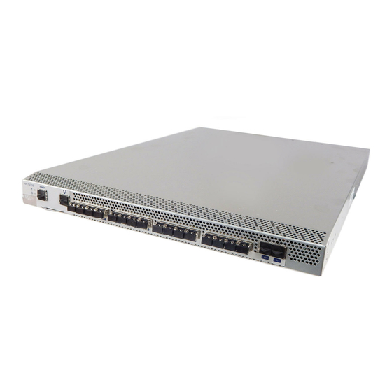
1 Console management (serial) port 5 System status LED 2 Ethernet management port 6 Power status LED 3 Fibre ports (0-15) 7 IP address tab location 4 GbE ports (2) Port side view Figure 1 EMC Connectrix B Series AP-7600B Hardware Reference Manual... - Page 17 Introduction The Fibre Channel ports are numbered from left to right, in eight-port groups, and are also numbered on the faceplate (see Figure IOIOI 1 Fibre Channel Ports 0 through 3 4 Fibre Channel Ports 12 through 15 2 Fibre Channel Ports 4 through 7 5 Gbe ports (2) 3 Fibre Channel Ports 8 through 11 Port numbering in the switch...
- Page 18 2 Power supply on/off switch 7 Power plug 3 Power supply 1 8 Power supply on/off switch 4 Fan assembly 3 9 Power supply 2 5 Fan assembly 2 Nonport side of the switch Figure 3 EMC Connectrix B Series AP-7600B Hardware Reference Manual...
-
Page 19: Managing The Switch
For information, see the Fabric Manager User’s Guide. connection Web Tools Ethernet or serial management port For information, see the Connectrix B Series 5.3 Web Tools connection Administrator’s Guide.. Standard SNMP applications Ethernet or serial management port For information, see the Fabric OS MIB Reference Manual. -
Page 20: Supported Features
The following optional software is available with the purchase of a specific license key: Fabric Watch ◆ ISL Trunking ◆ Performance Monitoring ◆ For information on these features, see the Connectrix B Series 5.3 Fabric OS Administrator’s Guide. EMC Connectrix B Series AP-7600B Hardware Reference Manual... -
Page 21: Installation
Installation This chapter provides information as a stand alone device or in a cabinet. Installation and safety considerations ..........22 ◆ Items included with the switch............24 ◆ Time and items required ..............25 ◆ Installing the switch................26 ◆ Setting up the switch as a standalone unit ........ -
Page 22: Installation And Safety Considerations
Ensure that airflow and temperature requirements are met on an ◆ ongoing basis, particularly if the switch is installed in a closed or multirack assembly. EMC Connectrix B Series AP-7600B Hardware Reference Manual... - Page 23 Installation Verify that the additional weight of the switch does not exceed the ◆ cabinet’s weight limits or unbalance the cabinet in any way. Secure the cabinet to ensure stability in case of unexpected ◆ movement. Installation and safety considerations...
-
Page 24: Items Included With The Switch
• One RJ-45 serial cable, approximately 3 m (10 feet) long. The switch uses an RJ-45 connector for serial port. An RJ-45 to DB9 adaptor is also provided with the switch. EMC Connectrix B Series AP-7600B Hardware Reference Manual... -
Page 25: Time And Items Required
Installation Time and items required Table 4 provides a list of installation tasks, the items required, and estimated time to complete each task. Installation tasks with time estimate and item required Table 4 Installation task Time estimate Items required Installing rack mount kit 30 minutes See the documentation contained in the kit you ordered. -
Page 26: Installing The Switch
Installation Installing the switch You can install the switch either as a standalone unit or within a standard EIA cabinet using a rack mount kit. EMC Connectrix B Series AP-7600B Hardware Reference Manual... -
Page 27: Setting Up The Switch As A Standalone Unit
The switch must be configured correctly before it can operate within a network and fabric. For instructions on configuring the switch, review the Connectrix B Series 5.3 Fabric OS Administrator’s Guide. Setup requirements The following items are required for configuring and connecting the... - Page 28 The serial cable provided with the switch ◆ An Ethernet cable ◆ SFP transceivers and compatible fibre cables, as required ◆ Access to an FTP server, for backing up (uploading) or ◆ downloading the switch configuration EMC Connectrix B Series AP-7600B Hardware Reference Manual...
-
Page 29: Installation Tasks
Installation Installation tasks To configure the switch, you must perform the following tasks: “Preparing to set up the switch” on page 29 “Create a serial connection” on page 30 “Connect to the switch using the serial connection” on page 31 “Set the switch IP address”... -
Page 30: Provide Power To The Switch
Windows or TERM in a UNIX environment) and configure the application as follows: • In a Windows NT, 2000, 2003, ME, or XP environment: – Bits per second:9600 – Databits: 8 – Parity: None – Stop bits: 1 EMC Connectrix B Series AP-7600B Hardware Reference Manual... - Page 31 Installation – Flow control: None • In a UNIX environment, enter the following command at the prompt: tip /dev/ttyb -9600 Connect to the switch using the serial connection To log in to the switch through the serial connection, follow these steps: 1.
- Page 32 Enter the configure command. The command prompts display sequentially; enter a new value or press Enter to accept each default value. c. Enter y after the “Fabric parameters” prompt: Fabric parameters (yes, y, no, n): [no] y EMC Connectrix B Series AP-7600B Hardware Reference Manual...
- Page 33 The ports selected for use in trunking groups must meet specific requirements. For a list of these requirements, see the Connectrix B Series 5.3 Fabric OS Administrator’s Guide. To install the transceivers: a. Remove the plugs from the ports to be used.
- Page 34 “MMDDhhmm[CC]YY” where: • MM is the month (01-12) • DD is the date (01-31) • hh is the hour (00-23) • mm is minutes (00-59) • CC is the century (19-20) EMC Connectrix B Series AP-7600B Hardware Reference Manual...
- Page 35 Installation • YY is the year (00-99) Year values greater than 69 are interpreted as 1970-1999; year values less than 70 are interpreted as 2000-2069. The date function does not support Daylight Savings Time or time zones, so changes will have to be reset manually.
- Page 36 (difference from UTC) Atlantic Standard -4,0 Atlantic Daylight -3,0 Eastern Standard -5,0 Eastern Daylight -4,0 Central Standard -6,0 Central Daylight -5,0 Mountain Standard -7,0 Mountain Daylight -6,0 Pacific Standard -8,0 Pacific Daylight -7,0 EMC Connectrix B Series AP-7600B Hardware Reference Manual...
- Page 37 For specific instructions about how to back up the configuration, see the Connectrix B Series 5.3 Fabric OS Administrator’s Guide. The switchShow, fabricShow, and Provide power to the switch...
- Page 38 Installation configUpload commands are described in detail in the Connectrix B Series 5.3 Fabric OS Command Reference Manual. EMC Connectrix B Series AP-7600B Hardware Reference Manual...
-
Page 39: Recommendations For Cable Management
Installation Recommendations for cable management Cables can be organized and managed in a variety of ways, such as by using cable channels or patch panels. Following is a list of recommendations: Plan cable management before installing the switch in a cabinet or ◆... - Page 40 Installation EMC Connectrix B Series AP-7600B Hardware Reference Manual...
-
Page 41: Operation And Maintentance
Operation and Maintentance This chapter provides information on operating and maintaining the switch. Maintenance approach ..............42 ◆ LEDs on the port side of the switch ..........43 ◆ Troubleshooting using the LEDs............45 ◆ LEDs on the nonport side of the switch.......... 47 ◆... -
Page 42: Maintenance Approach
Web Tools ◆ You can also set up monitoring alerts using SNMP, syslog, or software features (such as Web Tools). Refer to the Connectrix B Series 5.3 Fabric OS Web Tools Manual for additional information. Monitor system components System activity and status can be determined through the activity of the LEDs on the switch. -
Page 43: Leds On The Port Side Of The Switch
Operation and Maintentance LEDs on the port side of the switch The port side of the switch has the following LEDs: One system status LED (above) on the left side ◆ One power status LED (below) on the left side ◆... - Page 44 4 IP address pull out tab 10 Gbe ports (2) 5 Ethernet speed LED 11 A0 port 6 Ethernet link LED 12 A1 port LEDs on the port side of the switch Figure 4 EMC Connectrix B Series AP-7600B Hardware Reference Manual...
-
Page 45: Troubleshooting Using The Leds
“1”), the power cables attached, and your power source is live. If the system power LED is not green, the unit may be faulty. Contact your EMC Customer Service representative Steady green System is on and power supplies are No action required. - Page 46 The portCfgPersistentDisable command seconds; then off 2 is persistent across reboots. seconds) Fast-flashing amber SFP or port is faulty. Replace the SFP. (on 1/2 second; Reset the port. then off 1/2 second) EMC Connectrix B Series AP-7600B Hardware Reference Manual...
-
Page 47: Leds On The Nonport Side Of The Switch
The power cable is disconnected Verify that the power supply is powered on The power supply has failed Contact your EMC Customer Note: When the switch is first Service representative to replace the power supply FRU powered on the power supply status LED will show amber until POST has completed. -
Page 48: Interpreting Post Results
Web Tools). For information about how to turn beaconing on and off, see the Connectrix B Series 5.3 Fabric OS Administrator’s Guide or the Advanced Web Tools Administrator’s Guide. • Follow the recommended action for the observed LED... -
Page 49: Maintaining The Switch
Operation and Maintentance Maintaining the switch The switch is designed for high availability and low failure; it does not require any regular physical maintenance. It includes diagnostic tests and field-replaceable units, described in the following sections. Performing diagnostic tests In addition to POST, Fabric OS includes diagnostic tests to help you troubleshoot the hardware and firmware. - Page 50 Each fan assembly contains two fans, identified by Fabric OS as follows (viewing the switch from the nonport side): Fan assembly 1 on the right ◆ Fan assembly 2 in the center ◆ Fan assembly 3 on the left ◆ EMC Connectrix B Series AP-7600B Hardware Reference Manual...
- Page 51 Operation and Maintentance Any of the following methods can be used to determine whether a fan assembly requires replacing: Check the fan status LED on the face of the fan assembly (see ◆ “LEDs on the nonport side of the switch” on page 47).
-
Page 52: Powering Off The Switch
Operation and Maintentance Powering off the switch To power off the switch: 1. Using the CLI, enter the sysShutdown command. 2. Set each power supply AC power switch to “0”. EMC Connectrix B Series AP-7600B Hardware Reference Manual... -
Page 53: Chapter 4 Fan Assembly Replacement
Fan Assembly Replacement This chapter shows how to replace the fan assembly. Fan assembly replacement..............54 ◆ Fan Assembly Replacement... -
Page 54: Fan Assembly Replacement
. scale: 5/16" = 1" 1 Switch. 4 Fan assembly 2. 2 Nonport side. 5 Fan assembly 1. 3 Fan assembly 3. Switch fan assemblies on the nonport side Figure 5 EMC Connectrix B Series AP-7600B Hardware Reference Manual... -
Page 55: Time Required
Fan Assembly Replacement CAUTION Disassembling any part of the fan assembly voids the part warranty and regulatory certifications. There are no user-serviceable parts inside the fan assembly. Because the cooling system relies on pressurized air, do not leave any of the fan assembly slots empty longer than two minutes while the switch is operating. -
Page 56: Replacing A Switch Fan Assembly
The fan status can also be viewed using the Web Tools application. Figure 5 on page 54 for the locations of fan assembly 1, fan assembly 2, and fan assembly 3. EMC Connectrix B Series AP-7600B Hardware Reference Manual... - Page 57 Fan Assembly Replacement Scale: 1/4" = 1" 1 switch. 4 Handle. 2 Fan assembly. 5 Nonport side of switch. 3 Captive screw. Inserting the fan assembly to the switch Figure 6 Fan assembly replacement...
- Page 58 Fan Assembly Replacement EMC Connectrix B Series AP-7600B Hardware Reference Manual...
-
Page 59: Chapter 5 Power Supply Replacement
Power Supply Replacement This chapter explains how to replace the power supply in a switch. Power supply replacement ............... 60 ◆ Power Supply Replacement... -
Page 60: Power Supply Replacement
Scale: 1/8" = 1" Scale: 5/16" = 1" 1 Switch 3 Power supply 1 2 Nonport side 4 Power supply 2 Switch power supplies on the nonportside Figure 7 EMC Connectrix B Series AP-7600B Hardware Reference Manual... -
Page 61: Time Required
Power Supply Replacement CAUTION Disassembling any part of the power supply voids the part warranty and regulatory certifications. There are no user-serviceable parts inside the power supply. The cooling system relies on pressurized air, do not leave either of the power supply slots empty longer than two minutes when the switch is operating. -
Page 62: Replacing A Power Supply
(see Table 9 on page 61). If the LED is not a steady green, ensure that the power supply is securely installed and seated properly. EMC Connectrix B Series AP-7600B Hardware Reference Manual... - Page 63 Power Supply Replacement 9. Optionally, if using the Command Line Interface (CLI), enter the psShow command at the command line prompt to display power supply status. Power supply status can also be viewed using the Web Tools application. See Figure 8 for the location of Power supply 1 and Power supply 2.
- Page 64 Power Supply Replacement EMC Connectrix B Series AP-7600B Hardware Reference Manual...
- Page 65 Product Specifications This chapter provides information on product specifications and agency compliance information. Switch components................66 ◆ Weight and physical dimensions ............. 67 ◆ Power supply specifications............. 69 ◆ Environmental requirements............70 ◆ General specifications................ 71 ◆ Data transmission ranges..............72 ◆...
-
Page 66: Switch Components
They default to high speed upon boot, then switch to low speed as Fabric OS comes online, returning to high speed only as required. EMC Connectrix B Series AP-7600B Hardware Reference Manual... -
Page 67: Weight And Physical Dimensions
Product Specifications Weight and physical dimensions Table 10 provides a list of the weight and dimensions of the AP-7600B. Table 10 Physical specifications Dimension Value Height 1U = 42.44 mm (1.67 in.) Depth 635mm (25.0 inches) Width 429 mm (16.89 in.) Weight (with two power supplies and three fan assemblies installed) 12.43 kg (27.4 lbs) Facility requirements... - Page 68 • All equipment in cabinet must be grounded through a reliable branch circuit connection. • The additional weight of the switch must not exceed the cabinet’s weight limits. • The cabinet must be secured to ensure stability in case of unexpected movement. EMC Connectrix B Series AP-7600B Hardware Reference Manual...
-
Page 69: Power Supply Specifications
Product Specifications Power supply specifications The power supplies are universal and capable of functioning worldwide without voltage jumpers or switches. They meet IEC 61000-4-5 surge voltage requirements and are autoranging in terms of accommodating input voltages and line frequencies. Each power supply has a built-in fan for cooling, pushing air towards the port side of the switch. -
Page 70: Environmental Requirements
0 to 12 km (40,000 ft) above sea level Shock 20 G, 6 ms, half-sine wave 15 G, 12-18 milliseconds, trapezoid Vibration 0.5 G, 5-500 Hz 2.0 G, 5-500 Hz Air Flow 31 cu ft/min (52.7 cu m/hr) EMC Connectrix B Series AP-7600B Hardware Reference Manual... -
Page 71: General Specifications
Product Specifications General specifications Table 13 lists the general specifications for the switch. Table 13 General specifications Specification Description Configurable port types The Fibre Channel ports can be E_Ports, FL_Ports, or F_Ports. System architecture Nonblocking shared-memory switch System processor PowerPC 440GX, 800 MHz CPU ANSI Fibre Channel protocol FC-PH (Fibre Channel Physical and Signalling Interface standard) Modes of operation... -
Page 72: Data Transmission Ranges
80 km (50 mi) 4 Gbit/sec 150 m (492 ft) 62.5 70 m (230 ft) 10 km (6.2 mi) Up to 500km at 1G is supported when using long distance transport system such as DWDM. EMC Connectrix B Series AP-7600B Hardware Reference Manual... -
Page 73: Memory Specifications
Product Specifications Memory specifications The switch has three types of memory devices: Boot flash - 4 Mb ◆ Compact flash — 1 Gb ◆ Main memory (DDR SDRAM) — 1 Gb ◆ Memory specifications... -
Page 74: Fibre Channel Port Specifications
The ports meet all required safety standards. For more information about these standards, see “Regulatory compliance” on page The ports are capable of operating at 1-, 2-, or 4-Gbit/sec and are able to auto-negotiate to the maximum link speed. EMC Connectrix B Series AP-7600B Hardware Reference Manual... -
Page 75: Gbe Port Specifications
Product Specifications GbE port specifications The GbE ports in the switch are IEEE-compliant RJ-45.. The ports meet all required safety standards. For more information about these standards, see “Regulatory compliance” on page The GbE ports are capable of operating at 1-Gbit/sec. . GbE port specifications... -
Page 76: Serial Port Specifications
Table 15 lists the serial cable pinouts. Serial cable pinouts Table 15 Signal Description Not supported Not supported UART1_TXD Transmit data Logic ground Logic ground UART1_RXD Receive data Not supported Not supported EMC Connectrix B Series AP-7600B Hardware Reference Manual... -
Page 77: Post And Boot Specifications
Product Specifications POST and boot specifications The switch runs POST by default each time it is powered on; it typically requires approximatley 10 minutes to boot and complete POST. POST can be skipped after subsequent reboots by entering the fastBoot command. For more information about this command, see the Fabric OS Command Reference Manual. -
Page 78: Regulatory Compliance
Operation of this equipment in a residential area is likely to cause harmful interference, in which case the user will be required to correct the interference at the user’s own expense. MIC statement (Republic of Korea) EMC Connectrix B Series AP-7600B Hardware Reference Manual... - Page 79 The standards compliance label on the switch contains the CE mark which indicates that this system conforms to the provisions of the following European Council directives, laws, and standards: Electromagnetic Compatibility (EMC) Directive 89/336/EEC and ◆ the Complementary Directives 92/31/EEC and 93/68/EEC Low Voltage Directive (LVD) 73/23/EEC and the ◆...
- Page 80 This product is designed for an IT power system with phase-to-phase voltage of 240V. After operation of the protective device, the equipment is still under voltage if it is connected to an IT power system. EMC Connectrix B Series AP-7600B Hardware Reference Manual...
-
Page 81: Environmental Regulation Compliance
In no event do the EPUP logos shown on the product and FRU's alter or expand that warranty that provides with respect to its products as set forth in the applicable contract between EMC and its customer. EMC hereby disclaims all other warranties and representations with... - Page 82 Biphenyl (PBB) (PBDE) Fibre Channel Switch Fan, Blower assemblies PCBA cards Power Supply kit SFPs (optical cable connectors) Sheet Metal Chassis Assembly Mechanical brackets and Slides Slot Filler Cable management tray Cable Comb EMC Connectrix B Series AP-7600B Hardware Reference Manual...
- Page 83 Product Specifications China ROHS hazardous substances/toxic substances (HS/TS) Table 16 concentration chart (continued) Hazardous/toxic substance/elements Hexavalent Polybrominated Name of the Mercury Cadium chromium Polybrominated diphenyl ether component Lead (PB) (Hg) (CD) (CR6+) Biphenyl (PBB) (PBDE) Cables and power cords Replacement Doors Software/ Documentation...
- Page 84 主要部件名称 有害/有毒物质或元素 铅(Pb 汞(Hg 镉(Cd 六价铬(C 多溴联苯( 多溴二苯醚(PB R6+) PBB) DE) ) ) ) 光纤通道交换机 风扇/冷却组装件 线路板部件 电源 SFP(光纤接 头) 钣金件 机箱部件 机械支架及滑轨 插槽填充物 电缆整理盘 梳状线缆 线束及电源 线 替换门 软件/文档光盘 表示此类部件内同质材料中的有害/有毒含量高于SJ/T11363-2006的限量要求。 表示未使用此类物质或其含量低于上述限量要求。 EMC Connectrix B Series AP-7600B Hardware Reference Manual...
-
Page 85: Regulatory Certifications
Product Specifications Regulatory certifications Table 17 lists the safety and EMC (electromagnetic compatibility) specifications for which the switch is certified. EMC certifications Table 17 Country Safety specification EMC specification Argentina IEC 60950-1:2001 IEC 60825-1:1993+A1+A2 Australia and New Zealand EN 55022: 1998 Class A Canada CSA60950-1-03 1st Ed. - Page 86 Product Specifications EMC Connectrix B Series AP-7600B Hardware Reference Manual...
-
Page 87: Index
73 FCC warning (US only) 78 MIC statement (Republic of Korea) 78 Fibre Channel port specifications 74 Fibre Channel Ports performance of 13 field replaceable units (FRUs) 49 nonport side view 17 EMC Connectrix B Series AP-7600B Hardware Reference Manual... - Page 88 20 switch components 65 synchronize local time with an external source 35 time setting 34 VCCI statement 79 verify correct operation and backup the configuration 37 weight and physical dimensions 67 EMC Connectrix B Series AP-7600B Hardware Reference Manual...
Need help?
Do you have a question about the Connectrix B Series and is the answer not in the manual?
Questions and answers