EMC Connectrix B Series Hardware Reference Manual
Hide thumbs
Also See for Connectrix B Series:
- Hardware reference manual (218 pages) ,
- Reference manual (76 pages) ,
- Hardware reference manual (88 pages)

Related Manuals for EMC Connectrix B Series


Summary of Contents for EMC Connectrix B Series
- Page 1 ® ® Connectrix B Series MP-7500B v5.2.1a Hardware Reference Manual P/N 300-004-888 REV A01 EMC Corporation Corporate Headquarters: Hopkinton, MA 01748 9103 1000 www.EMC.com...
- Page 2 Copyright © 2007 EMC Corporation. All rights reserved. Published June, 2007 EMC believes the information in this publication is accurate as of its publication date. The information is subject to change without notice. THE INFORMATION IN THIS PUBLICATION IS PROVIDED “AS IS.” EMC CORPORATION MAKES NO...
-
Page 3: Table Of Contents
Set the switch domain ID............27 Install SFPs and cable the switch..........28 Set the switch date and time .............29 Synchronize local time with an external source.....30 Correct the time zone of a switch ..........30 EMC Connectrix B Series MP-7500B Hardware Reference Manual... - Page 4 POST..................... 70 Boot....................70 Regulatory compliance ..............71 FCC warning (US only) ............. 71 MIC statement (Republic of Korea) ......... 71 VCCI statement................72 BSMI statement (Chinese) ............73 CE statement ................74 EMC Connectrix B Series MP-7500B Hardware Reference Manual...
- Page 5 Contents Canadian requirements..............74 Laser compliance.................74 RTC battery ..................75 Electrical safety................75 Regulatory certifications ............76 Index ..........................77 EMC Connectrix B Series MP-7500B Hardware Reference Manual...
- Page 6 Contents EMC Connectrix B Series MP-7500B Hardware Reference Manual...
-
Page 7: Preface
Preface As part of an effort to improve and enhance the performance and capabilities of its product lines, EMC periodically releases revisions of its hardware and software. Therefore, some functions described in this document may not be supported by all versions of the software or hardware currently in use. For the most up-to-date information on product features, refer to your product release notes. - Page 8 Preface Related Related documents include: documentation EMC Connectrix B Series Diagnostic and System Error Message Reference Manual EMC Connectrix B Series Fabric Watch Reference Manual EMC Connectrix B Series Management Information Base (MIB) Reference Manual EMC Connectrix B Series Fabric OS Command Reference Manual EMC Connectrix B Series Web Tools Administrator’s Guide...
- Page 9 Preface Typographical conventions EMC uses the following type style conventions in this document: Normal Used in running (nonprocedural) text for: • Names of interface elements (such as names of windows, dialog boxes, buttons, fields, and menus) • Names of resources, attributes, pools, Boolean expressions,...
- Page 10 Technical support — For technical support, go to EMC Customer Service on Powerlink. To open a service request through Powerlink, you must have a valid support agreement. Please contact your EMC sales representative for details about obtaining a valid support agreement or to answer any questions about your account.
-
Page 11: Introducing The Mp-7500B Switch
Invisible Body Tag Introducing the MP-7500B switch This chapter provides the following information about the MP-7500B switch. Overview of the MP-7500B............... 12 Port side of the MP-7500B switch ............ 13 Nonport side of the MP-7500B ............15 Managing the MP-7500B ..............16 Supported features................ -
Page 12: Overview Of The Mp-7500B
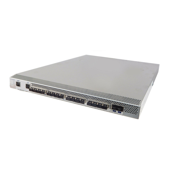
The MP-7500B is a 1U switch with 16 Fibre Channel SFP ports and 2 physical Gigabit Ethernet (GbE) ports. It includes the Fabric Operating System and is compatible with the entire EMC Connectrix B product family. It can operate independently or in a fabric containing multiple switches. -
Page 13: Port Side Of The Mp-7500B Switch
Introducing the MP-7500B switch Port side of the MP-7500B switch Figure 1 shows the port side of the MP-7500B. scale: 1/8" = 1" ra c in . fo r /6 4 g th le n re w g to x im ti n IOIOI Port side view of the MP-7500B... - Page 14 Fibre Channel Ports 4 through 7 GbE ports (2) The port side of the MP-7500B also displays the system status LED, power status LED, and port status LEDs (Figure 4 on page 39). EMC Connectrix B Series MP-7500B Hardware Reference Manual...
-
Page 15: Nonport Side Of The Mp-7500B
Introducing the MP-7500B switch Nonport side of the MP-7500B Figure 3 shows the nonport side of the MP-7500B, which contains the power supplies (including the AC power receptacle and AC power switch) and fans. scale: 1/8" = 1" x im ti n s c re g to... -
Page 16: Managing The Mp-7500B
IP over Fibre Channel managment port Up to two admin sessions and four user sessions simultaneously. For connection more information, see the Connectrix B Series Fabric OS Administrator’s Guide and the Fabric OS Command Reference Manual. Fabric Manager Ethernet or serial... -
Page 17: Supported Features
Performance Monitoring Fabric Watch Extended Fabric Trunking For information on these features, see the Connectrix B Series Fabric OS Administrator’s Guide. Features not supported The following feature is not supported: ISL Trunking is not supported on EX_Ports on the MP-7500B. - Page 18 Introducing the MP-7500B switch EMC Connectrix B Series MP-7500B Hardware Reference Manual...
-
Page 19: Installing And Configuring The Mp-7500B Switch
Invisible Body Tag Installing and Configuring the MP-7500B Switch This chapter provides the following information on installing the MP-7500B. Installation and safety considerations ..........20 Items included with the MP-7500B ..........21 Setting up the MP-7500B as a standalone unit....... 22 Installing in an EIA cabinet .............. -
Page 20: Installation And Safety Considerations
Verify that the additional weight of the switch does not exceed the cabinet’s weight limits or unbalance the cabinet in any way. • Secure the cabinet to ensure stability in case of unexpected movement EMC Connectrix B Series MP-7500B Hardware Reference Manual... -
Page 21: Items Included With The Mp-7500B
Installing and Configuring the MP-7500B Switch Items included with the MP-7500B The following items are included with the standard shipment of the MP-7500B: The MP-7500B switch, containing three fan assemblies and two power supplies One accessory kit, containing the following items: •... -
Page 22: Setting Up The Mp-7500B As A Standalone Unit
1. Clean the four corner depressions on the bottom of the switch and place a rubber foot in each one. This helps prevent the switch from accidentally sliding off the supporting surface. 2. Place the switch on a stable, flat surface. EMC Connectrix B Series MP-7500B Hardware Reference Manual... -
Page 23: Installing In An Eia Cabinet
Installing and Configuring the MP-7500B Switch Installing in an EIA cabinet The MP-7500B can be installed into an EIA cabinet using the optionally available rack mount kit. Refer to the documentation that is shipped with the rack kit for installation instructions. The switch can be installed using the slide rack mount kit in two ways: •... -
Page 24: Initial Setup Of The Mp-7500B
For instructions on configuring the switch to operate in a fabric containing switches from other vendors, see the Connectrix B Series Fabric OS Administrator’s Guide. The following items are required for configuring and connecting the... -
Page 25: Provide Power To The Switch
Installing and Configuring the MP-7500B Switch Provide power to the switch To provide power to the MP-7500B: 1. Connect the power cords to both power supplies and then to power sources on separate circuits to protect against AC failure. Ensure that the cords have a minimum service loop of 6 in. available and are routed to avoid stress. -
Page 26: Connect To The Switch Using The Serial Connection
3. Record the IP address on the pull out tab (see Figure 1 on page provided for this purpose on the port side of the MP-7500B. EMC Connectrix B Series MP-7500B Hardware Reference Manual... -
Page 27: Create An Ethernet Connection
Installing and Configuring the MP-7500B Switch 4. If the serial port is no longer required, log out of the serial console, remove the serial cable, and replace the plug in the serial port. Create an Ethernet connection To create an Ethernet connection to the MP-7500B: 1. -
Page 28: Install Sfps And Cable The Switch
A 50-micron cable should not be bent to a radius less than 2 in. under full tensile load and 1.2 in. with no tensile load. Tie wraps are not recommended for optical cables because they are easily overtightened. EMC Connectrix B Series MP-7500B Hardware Reference Manual... -
Page 29: Set The Switch Date And Time
Installing and Configuring the MP-7500B Switch a. Orient a cable connector so that the key (the ridge on one side of connector) aligns with the slot in the transceiver. Then, insert the cable into the transceiver until the latching mechanism clicks. For instructions specific to cable type, see the cable manufacturer’s documentation. -
Page 30: Synchronize Local Time With An External Source
2. Enter the tsTimeZone command as follows: tstimezone [houroffset [, minuteoffset]] For Pacific Standard Time, enter tsTimeZone -8,0 For Central Standard Time, enter tsTimeZone -6,0 For Eastern Standard Time, enter tsTimeZone -5,0 EMC Connectrix B Series MP-7500B Hardware Reference Manual... - Page 31 Installing and Configuring the MP-7500B Switch The default time zone for switches is universal time conversion (UTC), which is 8 hours ahead of Pacific Standard Time. Additional time zone conversions are listed later in this section. The parameters listed do not apply if the time zone of the switch(es) has already been changed from the default (8 hours ahead of PT).
-
Page 32: Fcip And Fibre Channel Routing Services Configuration
Online switchMode: Native switchRole: Subordinate switchDomain: switchId: fffc31 switchWwn: 10:00:00:05:1e:37:0d:a5 zoning: ON (cfg_em) switchBeacon: FC Router BB Fabric ID: 1 Area Port Media Speed State ============================== Online E-Port 10:00:00:60:69:e4:20:3e "sw48000" (upstre EMC Connectrix B Series MP-7500B Hardware Reference Manual... - Page 33 Installing and Configuring the MP-7500B Switch am)(Trunk master) No_Light Online LS E-Port (Trunk port, master is Port Online LS E-Port 10:00:00:60:69:e4:20:3e "sw48000" (Tru nk master) No_Light No_Light No_Light No_Light No_Light No_Light No_Light No_Light No_Light No_Light No_Light No_Light Online VE-Port 10:00:00:60:69:e4:20:3e "sw48000" Online VE-Port 10:00:00:60:69:e4:20:3e "sw48000"...
- Page 34 Connectrix B Series Fabric OS Administrator’s Guide. The switchShow, fabricShow, and configUpload commands are described in detail in the Connectrix B Series Fabric OS Command Reference. EMC Connectrix B Series MP-7500B Hardware Reference Manual...
-
Page 35: Recommendations For Cable Management
Installing and Configuring the MP-7500B Switch Recommendations for cable management Cables can be organized and managed in a variety of ways, such as by using cable channels or patch panels. Following is a list of recommendations: Plan cable management before installing the switch in a rack. Leave at least one meter of slack for each port cable. - Page 36 Installing and Configuring the MP-7500B Switch EMC Connectrix B Series MP-7500B Hardware Reference Manual...
- Page 37 Invisible Body Tag Operating the MP-7500B This chapter provides the following information about operating the MP-7500B switch. Interpreting LED activity ..............38 Interpreting POST results ..............43 Maintaining the MP-7500B ............... 44 Powering off the MP-7500B .............. 46 Operating the MP-7500B...
-
Page 38: Interpreting Led Activity
The port LEDs are located in the array in the same relative positions as the ports. One port status LED for each GbE port Figure 4 on page 39 shows the port side of the MP-7500B. EMC Connectrix B Series MP-7500B Hardware Reference Manual... - Page 39 Operating the MP-7500B IOIOI IOIOI scale: 5/16" = 1" scale: 3/4" = 1" LEDs on the Port side of the MP-7500B Figure 4 MP-7500B Ethernet Link LED System Status LED Ethernet Port System Power LED Fibre Channel Ports 0-3 Console Port Port 0 Status LED IP Address Pull Out Tab GbE ports...
- Page 40 No light There is no link. Verify that the Ethernet cable is connected correctly. Steady green There is a link. No action required. Flashing green There is link activity (traffic). No action required. EMC Connectrix B Series MP-7500B Hardware Reference Manual...
-
Page 41: Leds On The Nonport Side Of The Switch
Operating the MP-7500B Port Side LED patterns during normal operation (continued) Table 3 LED name LED color Status of hardware Recommended action Port Status No light Indicates one of the following: Verify the power LED is on, and check the SFP and cable. No signal or light carrier (media or cable) detected. - Page 42 Contact your EMC Customer the user Service Representative to replace the fan FRU Note: When the switch is first powered on the fan status LED will show amber until POST has completed. EMC Connectrix B Series MP-7500B Hardware Reference Manual...
-
Page 43: Interpreting Post Results
Operating the MP-7500B Interpreting POST results POST is a system check that is performed each time the switch is powered on, rebooted, or reset, and during which the LEDs flash different colors. To determine whether POST completed successfully and whether any errors were detected: Verify that the LEDs on the switch indicate that all components are healthy (LED patterns are described in... -
Page 44: Maintaining The Mp-7500B
The two power supplies are hot-swappable. They are identical and fit into either power supply slot. The Fabric OS identifies the power supplies as follows (viewing the switch from the nonport side): EMC Connectrix B Series MP-7500B Hardware Reference Manual... - Page 45 Operating the MP-7500B Power supply #1 on the right Power supply #2 on the left Any of the following methods can be used to determine whether a power supply requires replacing: Check the power supply status LED next to the On/Off switch (see “LEDs on the nonport side of the switch”...
-
Page 46: Powering Off The Mp-7500B
Operating the MP-7500B Powering off the MP-7500B To power off the MP-7500B: 1. Run the sysShutdown command. 2. Set each AC power switch to “0”. EMC Connectrix B Series MP-7500B Hardware Reference Manual... -
Page 47: Chapter 4 Removing And Replacing System Components
Removing and Replacing System Components This chapter includes the following sections: Fan assembly replacement..............48 Power supply replacement ............... 52 Removing and Replacing System Components... -
Page 48: Fan Assembly Replacement
Removing and Replacing System Components Fan assembly replacement Fan Assembly replacement should be performed by an EMC Customer Service Representative. CAUTION Customer servicing of the MP-7500B could result in the voiding of the warranty or service agreement. The MP-7500B switch has three fan assemblies as displayed in Figure 5. - Page 49 Removing and Replacing System Components CAUTION Disassembling any part of the fan assembly voids the part warranty and regulatory certifications. There are no user-serviceable parts inside the fan assembly. Because the cooling system relies on pressurized air, do not leave any of the fan assembly slots empty longer than two minutes while the switch is operating.
- Page 50 5. Optionally, display the fan status using the fanShow command from the CLI (see Figure 6 on page 51 for the locations of Fan assembly #1, Fan assembly #2, and Fan assembly #3). EMC Connectrix B Series MP-7500B Hardware Reference Manual...
- Page 51 Removing and Replacing System Components Scale: 1/4" = 1" Inserting the fan assembly in the MP-7500B switch Figure 6 MP-7500B switch Handle Fan Assembly Nonport side of switch Captive Screw Fan assembly replacement...
-
Page 52: Power Supply Replacement
Removing and Replacing System Components Power supply replacement Power supply replacement should be performed by an EMC Customer Service Representative. CAUTION Customer servicing of the MP-7500B could result in the voiding of the warranty or service agreement. The MP-7500B switch has two power supplies, as displayed in Figure 7. - Page 53 Removing and Replacing System Components CAUTION Disassembling any part of the power supply voids the part warranty and regulatory certifications. There are no user-serviceable parts inside the power supply. Because the cooling system relies on pressurized air, do not leave either of the power supply slots empty longer than two minutes while the switch is operating.
- Page 54 (see Table 6 on page 53). If the LED is not green, ensure that the power supply is securely installed, the power plug is secure, and the primary power is available. EMC Connectrix B Series MP-7500B Hardware Reference Manual...
- Page 55 Removing and Replacing System Components 9. Optionally, type the psShow command at the command line prompt to display power supply status (see Figure 8 for location of Power supply #1 and Power supply #2). Scale: 1/4" = 1" Inserting the power supply in the MP-7500B switch Figure 8 MP-7500B Handle...
- Page 56 Removing and Replacing System Components EMC Connectrix B Series MP-7500B Hardware Reference Manual...
- Page 57 Product Specfications This chapter provides the following information about MP-7500B requirements and specifications. Switch components................58 Weight and physical dimensions ............. 59 Facility requirements ................. 60 Power supply specifications............. 61 Environmental requirements............62 General specifications................ 63 Data transmission ranges..............65 Memory specifications ..............
-
Page 58: Switch Components
They default to high speed upon boot, then switch to low speed as Fabric OS comes online, returning to high speed only as required. EMC Connectrix B Series MP-7500B Hardware Reference Manual... -
Page 59: Weight And Physical Dimensions
Product Specfications Weight and physical dimensions Table 7 lists the weight and dimensions of the MP-7500B. Table 7 Physical specifications Dimension Value Height 1U = 42.44 mm (1.67 in.) Depth 635mm (25.0 inches) Width 429 mm (16.89 in.) Weight (with two power supplies and three fan assemblies 12.43 kg (27.4 lbs) installed) Weight and physical dimensions... -
Page 60: Facility Requirements
• All equipment in cabinet must be grounded through a reliable branch circuit connection. • The additional weight of the switch must not exceed the cabinet’s weight limits. • The cabinet must be secured to ensure stability in case of unexpected movement. EMC Connectrix B Series MP-7500B Hardware Reference Manual... -
Page 61: Power Supply Specifications
Product Specfications Power supply specifications The power supplies are universal and capable of functioning worldwide without voltage jumpers or switches. They meet IEC 61000-4-5 surge voltage requirements and are autoranging in terms of accommodating input voltages and line frequencies. Each power supply has a built-in fan for cooling, pushing air towards the port side of the switch. -
Page 62: Environmental Requirements
0 to 12 km (40,000 ft) above sea level Shock 20 G, 6 ms, half-sine wave 15 G, 12-18 milliseconds, trapezoid Vibration 0.5 G, 5-500 Hz 2.0 G, 5-500 Hz Air Flow 31 cu ft/min (52.7 cu m/hr) EMC Connectrix B Series MP-7500B Hardware Reference Manual... -
Page 63: General Specifications
Description Configurable port types The GbE ports can be VE_Ports or VEX_Ports. The Fibre Channel ports can be E_Ports, EX_Ports, FL_Ports, or F_Ports. EMC (electromagnetic compatibility) Emissions An operating MP-7500B conforms to the emissions requirements specified by the following regulations: FCC Rules &... - Page 64 128 Gbit/sec if all 16 FC ports are running at 4 Gbit/sec, full duplex 4 Gbit/sec if both GbE ports are running at 1 Gbit/sec, full duplex Port-to-port latency Less than 2 microseconds with no contention (destination port is free) EMC Connectrix B Series MP-7500B Hardware Reference Manual...
-
Page 65: Data Transmission Ranges
Product Specfications Data transmission ranges Table 11 provides the data transmission ranges for different cable types and port speeds. Data transmission ranges Table 11 Cable size Short wavelength Long wavelength Extended long Port speed (microns) (SWL) (LWL) wavelength (ELWL) 1 Gbit/sec 500 m (1,640 ft) 62.5 300 m (984 ft) -
Page 66: Memory Specifications
Product Specfications Memory specifications The MP-7500B has three types of memory devices: Boot flash - 4 MB Compact flash - 1 G Main memory (SDRAM) - 512 MB EMC Connectrix B Series MP-7500B Hardware Reference Manual... -
Page 67: Fibre Channel Port Specifications
Product Specfications Fibre Channel port specifications The Fibre Channel ports in the MP-7500B are compatible with SWL, LWL, and ELWL SFP transceivers. The strength of the signal is determined by the type of transceiver in use. The ports meet all required safety standards. For more information about these standards, see “Regulatory compliance”... -
Page 68: Gbe Port Specifications
“Regulatory compliance” on page The GbE ports are capable of operating at 1-Gbit/sec. The 8 virtual FCIP Fibre Channel links over each physical GbE connection share this bandwidth. EMC Connectrix B Series MP-7500B Hardware Reference Manual... -
Page 69: Serial Port Specifications
Product Specfications Serial port specifications The serial port is located on the port side of the switch. The MP-7500B uses an RJ-45 connector for serial port. An RJ-45 to DB9 adaptor is also provided with the switch. Note: To protect the serial port from damage, keep the cover on the port when not in use. -
Page 70: Post And Boot Specifications
POST can be skipped after subsequent reboots by entering the fastBoot command. For more information about this command, see the Connectrix B Series Fabric OS Command Reference Manual. POST The success/fail results of the diagnostic tests that run during POST can be monitored through LED activity, the error log, or a command line interface. -
Page 71: Regulatory Compliance
Product Specfications Regulatory compliance This section describes the regulatory compliance requirements for the MP-7500B. It contains: • “FCC warning (US only)” on page 71 • “MIC statement (Republic of Korea)” on page 71 • “VCCI statement” on page 72 • “BSMI statement (Chinese)”... -
Page 72: Vcci Statement
Control Council for Interference by Information Technology Equipment (VCCI). If this equipment is used in a domestic environment, radio disturbance might arise. When such trouble occurs, the user might be required to take corrective actions. EMC Connectrix B Series MP-7500B Hardware Reference Manual... -
Page 73: Bsmi Statement (Chinese)
Product Specfications BSMI statement (Chinese) Regulatory compliance... -
Page 74: Ce Statement
Canadian Interference-Causing Equipment Regulations, ICES-003 Class A. Laser compliance This equipment contains Class 1 laser products and complies with FDA Radiation Performance Standards, 21 CFR Subchapter I and the international laser safety standard IEC 825-2. EMC Connectrix B Series MP-7500B Hardware Reference Manual... -
Page 75: Rtc Battery
Product Specfications CAUTION Use only optical transceivers that are qualified by EMC and comply with the FDA Class 1 radiation performance requirements defined in 21 CFR Subchapter I, and with IEC 825-2. Optical products that do not comply with these standards might emit light that is hazardous to the eyes. -
Page 76: Regulatory Certifications
EN 61000-3-2 Limits for Harmonic Current Emissions Malta, Poland, EN 61000-3-3 Flicker Portugal, Slovakia, Slovenia, Spain, Sweden, The Netherlands, United Kingdom) and Republic of Korea Australia and New EN 55022: 1998 Class A Zealand EMC Connectrix B Series MP-7500B Hardware Reference Manual... -
Page 77: Index
60 MIC statement (Republic of Korea) 71 FCC warning (US only) 71 FCIP and Fibre Channel Routing Services configuration 32 FCIP tunneling service 11, 19, 37, 47, 57 nonport side view 15 EMC Connectrix B Series MP-7500B Hardware Reference Manual... - Page 78 22 supported features 17 synchronize local time with an external source 30 time setting 29 VCCI statement 72 verify correct operation and backup the configuration 32 weight and physical dimensions 59 EMC Connectrix B Series MP-7500B Hardware Reference Manual...
Need help?
Do you have a question about the Connectrix B Series and is the answer not in the manual?
Questions and answers