
Related Manuals for FLASHFORGE 3D PRINTER Inventor II S


Summary of Contents for FLASHFORGE 3D PRINTER Inventor II S
- Page 1 FlashFor ge Inventor IIS 3D Pr inter User Guide InventorIIS User Guide | www.flashforge.com...
-
Page 2: Table Of Contents
Content Content..........................2 Preface..........................3 Introduction........................4 Notice..........................5 Chapter 1: 3D Printing Technology................8 Chapter 2: About InventorⅡS..................10 2.1 About Your InventorⅡS................. 10 Chapter 3:Unpacking....................23 Chapter 4: Hardware Assembly..................27 4.1 Filament Installation..................27 4.2 Printer Start-up....................28 4.3 Loading Filament.....................28 4.4 Unloading Filament..................30 Chapter 5: Build Plate Leveling..................32 Chapter 6: About Software................... -
Page 3: Preface
On the completion of this User Guide, thanks all FlashForge engineers and the FlashForge 3D printer users for their unremitting efforts and sincere assistance. The FlashForge InventorⅡS User Guide is designed for the InventorⅡS users to start their printing journey with FlashForge Inventor Ⅱ... -
Page 4: Introduction
Intr oduction Notes: ·Please read FlashForge InventorIIS 3D Printer User Guide carefully before use. ·The User Guide is written based on Windows 7 OS. ·The version of the FlashPrint is latest. The FlashForge Inventor Ⅱ S 3D Printer User Guide contains the information needed for you to set up and use this device. -
Page 5: Notice
Notice Safety Notice ! Notices: Read all the instructions in the manual and familiarize yourself with the FlashForge Inventor Ⅱ S User Guide before setting-up and using. Failure to comply with the warning and instructions may result in individual injury, fire, equipment damage or property damage. - Page 6 ③ Dress properly. Do not wear loose clothing or jewelry. Keep your hair, clothing and gloves away from moving parts. ④ Do not operate the device while you are tired or under the influence of drugs, alcohol or medication. · Cautions ①...
- Page 7 · Filament Requir ements Do not abuse the filament. Please make sure you use the FlashForge filament or the filament from the brands accepted by FlashForge. · Filament Stor age All polymers degrade with time. Do not unpack filament until necessary. Filament should be stored at clean and dry conditions.
-
Page 8: Chapter 1: 3D Printing Technology
Chapter 1: 3D Pr inting Technology 3D printing refers to transforming three-dimensional models into physical objects that you can hold and touch. It is also called additive manufacturing because the 3D model is created by “adding” layers upon layers of material until the object is fully formed. Fused Filament Fabrication (FFF) is the most common method of 3D printing. - Page 9 ·Fr om the Cloud The most popular way of obtaining a 3D model is to download it from websites that allow users to upload 3D models that they designed. E.g. : www. thingiverse.com 1.1.2 Slice and Expor t the 3D Model: Slice software is the software that prepares 3D models for printing and turns them into instructions for the 3D printers.
-
Page 10: Chapter 2: About Inventorⅱs
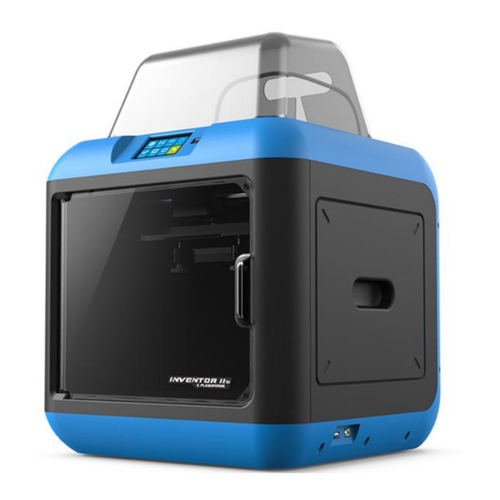
Chapter 2: About Inventor ⅡS 2.1 About Your Inventor ⅡS 2.1.1 Views Front Right Back 1. Touch screen 6. Leveling knob 11. Spring presser 12. Camera 7. Filament cartridge 2. Touch screen button 13. USB cable input 8. Extruder 3. Nozzle 14. - Page 11 2.1.2 Ter ms The surface on which the InventorⅡS builds an object. InventorIIS has an extracting magnet build plate, which is composed of 3 parts: build tape, flexible metal sheet and Build Plate magnetic patch. It is convenient for users to take down the model, and can be used directly as operating platform for processing model result.
- Page 12 2.1.3 Refer ence InventorⅡS Name Number of Extruder Print Technology Fused Filament Fabrication(FFF) Screen Size 3.5’’ color IPS Touch Screen Build Volume 150×140×140mm Layer Resolution 0.1 - 0.4mm Build Accuracy ±0.1mm Positioning Accuracy Z axis 0.0025mm; XY axis 0.011mm 1.75mm(±0.07) Filament Diameter Nozzle Diameter 0.4mm...
- Page 13 2.1.4 Inter face Menus Build Read the print file from The internal memory The USB stick The Polar Cloud Connection Back Select the target print file among the list Build: To begin printing Copy: To copy the files to the local memory card from the USB stick.(The button is not available while printing from internal memory )
- Page 14 To set extruder temperature during printing: After extruder temperature has reached target temperature, temperature figure will be underlined in print interface, Tap the temperature figure to adjust; Tap [Yes] to save the setting while tap [No] to cancel the setting. 180—240℃...
- Page 15 Tap the [Pr eheat] button to enter the preheat interface. Tap the [Star t] button to heat up to the setting temperature. The default temperature is 220℃. Tap the temperature display bar to set the temperature. To set the preheat temperature. Tap [Yes] to save the setting while tap [No] to cancel the setting.
- Page 16 Tools Tap [Tools] to enter tool options. Filament: To load/unload the filament. Level: To adjust the build plate. Home: To make the X, Y and Z axes back to the zero point. Manual: To manually adjust the positions of X, Y and Z axes.
- Page 17 Tap [Setting] to enter the setting interface Language: To set the display language WiFi: To turn on/off the WiFi WLan hotspot: To turn on/off the WLan hotspot. Polar Cloud Connection: To turn on/off the Polar Cloud Connection. ...
- Page 18 WiFi: Turn on WiFi: Turn on the WiFi, release the WiFi hotspot and set the WiFi on computer Back WLan hotspot OFF/On: To turn on/off the Wlan hotspot. Setup Wlan hotspot: To set the SSID and password. SSID: The name of hotspot. Password: The password of hotspot.
- Page 19 Cloud Connection: To turn on/off the polar cloud connection. Setup Cloud Connection: To set cloud connection Account and PIN which have already been registered on: https://polar3d.com Account: The email address of your Cloud account. PIN: The PIN code of your Cloud account.
- Page 20 [Filament Check] Off: The filament detection is turned off. Note: Filament exhausted or interrupted cannot be detected.The print job can still work normally when filament is not set into the filament cartridge. [Door Opened Pause] On: If printer front door is opened during printing, door opened pause hint will pop out on printer touch screen.
- Page 21 Status: It displays the real-time status of the extruder temperature, door, filament and original extruder position. About:(First page) It displays the basic information about the device. About:(Second page) It displays the basic information about the device. License It displays the basic information about the license.
- Page 22 Accessor ies Filament*1 Power Adapter Power Cable USB Cable Filament Guide Tube Quick Start Guide USB Stick Screwdriver Allen Wrench Solid Glue Stamping Wrench Unclogging Pin Tool After-sale Service Card PTFE Tube Grease InventorIIS User Guide | www.flashforge.com...
-
Page 23: Chapter 3:Unpacking
Chapter 3:Unpacking (r efer ence video:Unpacking) This chapter will present you the whole unpacking procedure of InventorⅡS 3D printer.(Note: Make sur e you r ead the whole unpacking guide) (3-1) Place the packaging box on a clean work surface InventorIIS User Guide | www.flashforge.com... - Page 24 Open the box, grasp the two handles and then lift your InventorⅡS out of the (3-2) box. (3-3) Remove the accessory box, you can see a quick start guide and an after-sales service card, in the box it contains a power adapter, a power cable, glue stick, USB cable, guide tube and accessory bag(USB stick*1, stamping wrench*1, unclogging pin tool*1, and screwdriver*1 Allen wrenches*2, Grease and PTFE tube.) (3-4) Remove the side protective foam sheets.
- Page 25 (3-5) Remove the bag to unveil the InventorⅡS (3-6)Remove the top foam sheet (3-7)Remove the tape on for fixing the flat cable and cut off four ribbons that used for fixing the guide rod. Then slide the extruder to make sure the extruder is in good condition.
- Page 26 (3-8) Slightly squeeze the bottom of the lid, and remove it carefully. (3-9) Take out the left foam, left the build plate up and take out the protective foam. (3-9) Take out left side foam sheet. Elevate the build plate up and then take the bottom foam sheet out.
-
Page 27: Chapter 4: Hardware Assembly
Chapter 4: Har dwar e Assembly Your Inventor Ⅱ S has been installed before leaving factory, you can start up the InventorⅡS for printing after mounting the filament spool and completing leveling. 4.1 Filament Installation (4-1) The filament cartridge is at the rear of InventorⅡS. Lift the cartridge out of the InventorⅡS. -
Page 28: Printer Start-Up
4.2 Pr inter Star t-up Power Input Power switch (4-3) Insert the power supply into the power input on the back of the InventorⅡS and plug the power cord into an electrical outlet. 4.3 Loading Filament For stable filament loading and proper device protection, you need to install the filament guide tube properly. - Page 29 (4-6) Insert the filament from the filament guide tube into the filament intake. Next, we will load the FlashForge filament.(Note: Please lower the build plate to incr ease the distance between the nozzle and build plate to 50mm at least for avoiding nozzle jam.) (4-7) Tap [Tool].
-
Page 30: Unloading Filament
(4-9)After the extruder’s temperature reaching 220℃, the printer will sound a beep to prompt you to load the filament into the extruder. 4-10 (4-10) Insert the filament into the extruder at an upright angle. Then the filament will be drawn through the extruder. Do not tap [Cancel] until the filament load the extruder steadily. - Page 31 4-12 、 (4-12) After the extruder reaching 220℃, the printer will sound a beep to prompt you to unload the filament from the extruder. Press the spring presser, press down the filament for about three seconds and gently pull the filament out. Note: Do not pull out the filament with for ce as it will damage the gear s.
-
Page 32: Chapter 5: Build Plate Leveling
Chapter 5: Build Plate Leveling InventorⅡS creatively adopts three-point intelligent leveling system, which will give clear and comprehensive feedback to users. There are three spring-loaded knobs under the build platform. The distance between the plate and nozzle increases while tightening the knobs. On the contrary, the distance reduces. (5-1) Tap [Tools]-[Level] on your Inventor Ⅱ... - Page 33 (5-2) After tapping [Yes], the extruder starts to move towards the first point and the plate moves up and down to verify the distance between nozzle and plate. (5-3) When it shows that the distance is too big, please unscrew corresponding nut under platform clockwise until hearing a steady beep and the [Ver ify] button appears.
-
Page 34: Chapter 6: About Software
Chapter 6: About Softwar e This chapter talks about the basic function of FlashPrint. For more information about advanced function, you can browse our website www.FlashForge.com. 6.1 Softwar e Installation 6.1.1 Softwar e Acquisition Method 1: To get the installation package from the USB disk in the toolkit. Method 2: Open the link below to download the installation package: http://www.FlashForge.com Steps:... - Page 35 Note! After starting FlashPrint, you need to select the target machine type first. When you start FlashPrint, a dialog box will pop up. Just select FlashForge InventorIIS in the machine type list and click [OK]. You can also change the machine type via clicking [Pr int]--[Machine type].
- Page 36 Load files. Enter the support edit mode Print it directly with your InventorIIS or export to your USB Stick View FlashPrint home screen from one of six viewing angles Move model around on XY-plane; shift+click to move along Z axis Turn and rotate your model Scale the size of your object Cut model into several parts...
- Page 37 Note: .STL, .OBJ , and .FPP, ways to store 3D models, are supported by FlashPrint for editing. Gener ating Rilievo Load a png, jpg, jpeg, bmp picture file into the FlashPrint. And the following dialogue box (6-3) will pop up. The setting box includes settings for shape, mode, maximum thickness, base thickness, bottom thickness, width, height, top diameter and bottom diameter.
- Page 38 Plane (6-5) Tube(6-6) Canister (6-7) InventorIIS User Guide | www.flashforge.com...
- Page 39 Lamp (6-8) Seal (6-9) 6.2.4 Views ①Changing views Change model views by moving, rotating, scaling. ● Dr ag Click the [View] icon and then you can move the object by the following three methods: Method 1: Hold down the left mouse button and drag. Method 2: Hold down the mouse wheel and scroll up and down.
- Page 40 Method 3: Hold down the Shift key, hold down the right mouse button and drag. ● Rotate Click the [View] icon and then you can rotate the object by the following two methods: Method 1. Hold down the right mouse button and drag. Method 2.
- Page 41 ⑤Show Steep Over hang Click [View]--[Show Steep Over hang]. When the intersection angle between the model surface and horizontal line is within the overhang threshold value, the surface has steep overhang and it becomes red in the software. Overhang threshold value could be set as needed.
- Page 42 6.2.7 Scale Select the target object and scale the object by the following two methods: Method 1: Click the [Scale] icon on the left, hold down the left mouse button and scale the model. The corresponding values will display near the object. Method 2: Click the [Scale] icon on the left and then enter into scale values in X/Y/Z...
- Page 43 ③Y Plane ④Z Plane 6.2.9 Suppor ts After loading the model, click [Edit]--[Suppor ts] or click the Suppor ts icon directly, then you will enter the support edit modem (as shown in the picture below). Click [Back] to exit when you finish editing. 6-10 InventorIIS User Guide | www.flashforge.com...
- Page 44 ①Suppor t Options Click the Support Options, an option box will appear, supports options include “treelike” and “linear”, when choose “treelike”, click [OK], then it will generate treelike structure; when choose “linear”, click [OK], then it will generate linear structure; if it is a model with supports, when you choose one of the supports options, software will judge whether existing supports need to be deleted or not on the basis of the type of existing support, and will pop up the corresponding prompt to let you make the choice.
- Page 45 meet with model, then support will be generated on origin and terminal point(the highlighted preview support won’t generate support structure) Clear Suppor ts ④ Click [Clear Suppor ts], all supports will be deleted. The operation can be repealed via clicking [Undo] or pressing the shortcut key l+Z.
- Page 46 ②Pr int when slice done: Print or not when slice done ③Mater ial type: Choose according to the type of model ④ Suppor ts: When print suspended structure models, support is necessary. Click [suppor ts] to create support part for the printing. ⑤Raft: This function will help the model to stick well on the platform.
- Page 47 b. Bottom Solid Layer : Maximum is 30, minimum is 1. ● Infill a. Fill Density means fill rate. b. Fill Patter n is the pattern of filling shape which effects printing duration. c. Combine Infill: You can select the layers for combining according to the layer thickness.
- Page 48 needs to be saved or not. Click [Yes] will save the modification, while click [No] will abandon it. If click [Cancel] or close tool tip, then will cancel the new project. 6-13 ②Saving After finishing the model edit and adjustment, there are two ways below to save all models in the scene.
- Page 49 ● Font Size: Set the font size. ● Auto layout newly-impor ted model: Set Yes or No. ● Pr inting Window Type: Including Basic Mode and Expert Mode ● Check for Update after star t up: It is used to preset if it is necessary to activate the online automatic update function, if choose yes, every time when you open software, it can online detect if it is a new version software, once new version found, it will reminds users to download and install new version firmware.
- Page 50 Select the object and duplicate the object through the following two methods: Method 1: Click [Edit]--[Duplicate] Method 2: Press the shortcut Ctr l+D Delete ⑥ Select the object and delete the object through the following two methods: Method 1: Click [Edit]--[Delete] Method 2: Press the shortcut Delete...
- Page 51 6.2.13 Pr int Menus ① Connect Machine You can connect the InventorIIS with your PC via a USB cable or WiFi. Note: The machine icon on the bottom right displays the connection status: Connected Disconnected Method 1:Connect Via USB Cable a.
- Page 52 Method 2: Connect Via WiFi ①Connect Inventor ⅡS with your PC under AP mode a.Turn on your InventorⅡS b. Tap [Tools]-[Setting]-[WLan hotspot]-[WLan hotspot ON]. c. Click on the wireless network setting in your computer, and find the wireless signal-“Inventor Ⅱ”. Click [Connect] to connect your computer with Inventor Ⅱ...
- Page 53 6-18 If successfully connected, you will see the following red mark. 6-19 Disconnect Inventor ⅡS Click [Pr int]--[Disconnect] to disconnect your PC and InventorIIS. 6.2.14 Tool Menus ①Contr ol Panel After connecting PC with InventorIIS, click [Tools]--[Contr ol Panel] to open the control panel.
- Page 54 ● J og Contr ols J og Mode:Select the distance that extruder/ build plate move a single time (that is, the distance extruder/ build plate move upon your single click). Six blue ar r ow dir ection buttons: Control the move along X/Y/Z axis. X/Y axis button control extruder move, Z axis button control build plate move.
- Page 55 ● Stepper Motor Contr ols: Allows users to control to stepper motor. Click [Enable], and lock the motor so it does not allow any movement; click [Disable], and unlock the motor to be controlled manually. ● LED Color : Allow users to change the LED color of Inventor ⅡS. ●...
- Page 56 Step 2: Choose corresponding printer type and firmware version and click [OK] in the firmware updating box. After confirming the printer is in free state, the software will automatically update the firmware. 6-22 Step 3: Reboot you Inventor ⅡS and wait for 4-5 seconds, then you can see the update process bar.
- Page 57 6.2.15 Help Menus ① Fir st Run Wizar d ② Help Contents:Click [Help]--[Help Contents], you can read the help contents. ③ Check for Updates : Click [Help]--[Check for Update] to detect the available updates online. ④ About FlashPr int : Click [Help]--[About FlashPr int], the software information...
-
Page 58: Chapter 7: Basic Printing
Chapter 7: Basic Pr inting This chapter will provide a step-by-step guide on turning a 3D model into a physical reality. Before proceeding, it is recommended that you’d better go over prior chapters on loading/unloading filament, leveling the build platform, and the functions and capabilities of FlashPrint. - Page 59 the Platfor m] [Center ] to ensure the model be on the platform. Note:If you’ve place your model in a r ight place, you can skip the step above. (7-5) Click the [Pr int] icon on the top, you should make some setups for your print job.
-
Page 60: Print Methods
you print via USB stick, you should not check the box. Machine Type: FlashForge InventorⅡS Suppor ts: If you print a model with supports, you should click the inverted triangle and select [Enable]. Raft: You are suggested to select [Enable]. Resolution: You are suggested to select [Standar d] Mor e Options: You are suggested to keep them default. - Page 61 completing transference, the printer will heat up automatically. And when heating finishes, the print will start to build the model. When your PC connects with FlashPrint successfully. The status box on the ④ bottom right displays the real-time nozzle temperature. After finishing preheating, your InventorⅡS starts the print job directly.
- Page 62 ● Click the [Pr int] button, the PC will transfer the Gcode file to the printer. 7-10 ● After finishing transferring, the printer will heat up automatically. And when heating finishes, the print will start to build the model. InventorIIS User Guide | www.flashforge.com...
- Page 63 7-11 7.2.3 Pr int fr om USB Stick ①Insert your USB stick with target .g or .gx file to your InventorⅡS. Turn on the Inventor Ⅱ S. Make sure the build plate has been leveled and the ② filament is loaded. [Pr int] and then tap the icon in the middle.
- Page 64 7.2.4 Pr int fr om FlashFor ge Cloud connection 1) Turn on [WiFi] connection on printer’s setting interface to connect the printer to Internet with WiFi. Turn on [FlashForge Cloud] connection on printer’s setting interface. 2) Register a FlashForge Cloud account with your computer, on website: https://cloud.sz3dp.com/ 3) Register your account on FlashForge cloud: After activate your account through your email box, login in Flashforge cloud with your account.
- Page 65 5) Add a printer completed as showed in the picture below. More than one of the Flashforge printers can be added to a FlashForge Cloud account, Flashforge Finder, InventorII/InventorIIS, Adventurer3 printers all support FlashForge Cloud connection. Using FlashForge Cloud connection print, printers and print jobs management can be done in batches.
- Page 66 7) Select the printer for this print job on left upper position, Click[Print]. Click[Start] to start printing, the selected printer will start printing automatically. Time remaining for this print job, instant extruder/buildplate temperature or other printing details are all showed in this webpage, you can also pause or cancel this print job anytime during printing process.
- Page 67 7.2.5 Pr int fr om Polar Cloud connection 1)Register a Polar Cloud account with your computer, on website: https://polar3d.com/ Register your account using one of the four following options, take the third microsoft live option as an example, create your new Polar Cloud account. 2)Enter the Polar Cloud homepage after you create your Polar Cloud account.
- Page 68 Connect the printer to internet with WiFi; Tap [Tools]-[Settings]-[Polar Cloud connection] on printer’s touch screen; Input your polar 3D cloud account’s Email address(as Account) and PIN Code, Tap[save] . InventorIIS User Guide | www.flashforge.com...
- Page 69 3)Enter the Polar Cloud homepage with your computer again. Tap [Explore] on the left upper corner showed in the picture below, then Tap [Objects] Enter the objects page, choose a model you are going to print. Tap【3D PRINT】button InventorIIS User Guide | www.flashforge.com...
- Page 70 Tap【PRINT】button Tap【START】button,the printer starts downloading printing file automatically,after downloading completed,you can interactively operate the printer on your computer, including Change Filament, Pause, Stop etc. 4) More than one of the Flashforge printers can be added to a Polar 3D Cloud account, Flashforge GuiderIIS/GuiderII, Finder, InventorIIS/InventorII, Adventurer3 printers all support Polar 3D Cloud connection.
- Page 71 uploading your own sliced print files. Print files can be transferred to corresponding printer and printing will be started automatically. You can also adjust the extruder temperature, or explore other cloud functions. 6)Delete a printer from a polar cloud account.(If someone else wants to use the same printer under another polar cloud account, please make sure you’v delete the printer from your current-using polar cloud account, or others can not use the printer.) InventorIIS User Guide | www.flashforge.com...
- Page 72 Click the printer you want to delete. Click [MANAGE] button on the right upper position of this printer’s details webpage. Then click [SETTINGS] button on the right upper position of the next webpage. Finally, drag the next page to bottom down, click [DELETE PRINTER] button. After you’v completed the above delete steps, this printer can now be used by others under his own polar cloud account.
-
Page 73: Camera
7.3 Camer a 7.3.1 Connect fr om Polar Cloud For detailed connection method,please refer to 7.2.5 After InventorIIS printer has added to Polar Cloud account and connected successfully (InventorIIS printer and your computer should link to Internet by WiFi, printer and computer do not need to connect the same WiFi signal), Then InventorIIS printer’s camera can be used to monitor the real-time printing status. -
Page 74: Chapter 8: Supports And Service
Chapter 8: Suppor ts and Ser vice FlashForge team is on standby and ready to help you with any challenges you may have with your InventorIIS. If the issues or questions are not covered in this User Guide, you can seek for solutions on our official website or contact us via telephone. There are solutions and instructions to common issues that can be found in our knowledge base.
Need help?
Do you have a question about the Inventor II S and is the answer not in the manual?
Questions and answers