Table of Contents
Advertisement
Quick Links
Download this manual
See also:
User Manual
Advertisement
Table of Contents

Related Manuals for Multitech CC1600 Series


Summary of Contents for Multitech CC1600 Series
- Page 1 CC1600-Series MT2834BLR Intelligent Data/Fax Modem Owner’s Manual...
- Page 2 Multi-Tech Systems, Inc. 2205 Woodale Drive Mounds View, Minnesota 55112 U.S.A. (612) 785-3500 or (800) 328-9717 U. S. FAX 612-785-9874 Fax-Back Service 612-717-5888 Technical Support (800) 972-2439 BBS (612) 785-3702 or (800) 392-2432 Internet Address: http://www.multitech.com Technical Writer: brian@multitech.com...
-
Page 3: Table Of Contents
Contents Chapter 1 - Introduction and Description Introduction ............................6 Features ............................6 How to Use This Manual ......................... 7 Chapter 2 - Installation and Connection Preliminaries ............................ 10 2.1.1 Card Cage .......................... 10 2.1.2 Serial Cable ........................10 2.1.3 Telephone Line ........................ - Page 4 Chapter 4 - Modem AT Commands Modem AT Commands ........................32 4.1.1 Callback Security Commands .................... 42 4.1.2 V.25bis Commands ......................43 4.1.3 Remote Configuration ......................44 4.1.4 Remote Configuration Procedures ..................44 S-Registers ............................. 45 Result Codes ........................... 49 4.3.1 AT Commands and S-Register Summary ................
-
Page 5: Chapter 1 - Introduction And Description
CC1600-Series Chapter 1 - Introduction and Description... -
Page 6: Introduction
MT2834BLR Owner’s Manual Introduction Welcome to the world of data communications. You have acquired one of the finest intelligent data/ fax modems available today, model MT2834BLR, from Multi-Tech Systems. Your MT2834BLR modem provides data communication at 33,600-14,400 bps (*Enhanced V.34/V.32terbo/V.32bis), as well as other prevalent datacomm standards. -
Page 7: How To Use This Manual
Chapter 1 - Introduction and Description How to Use This Manual This chapter begins with a short introduction, a profile on modem features, followed by a guide (which you are now reading) to the use of this manual. This manual includes hardware installation and configuration described in Chapter Chapter 3... - Page 8 MT2834BLR Owner’s Manual...
-
Page 9: Chapter 2 - Installation And Connection
CC1600-Series Chapter 2 - Installation and Connection... -
Page 10: Preliminaries
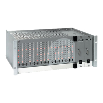
The rack has a sixteen modem slot capacity, one power supply source (the CC1600 series card cage has a redundant power supply capability), sixteen 25- pin (female) connectors for RS-232C/V.24 interface and sixteen DB-9 (female) connectors for phone line (the CC1600 series card cage has RJ-11 back-plane connectors for phone line interface). -
Page 11: Installation
Chapter 2 - Installation and Connection Installation Perform the following procedure to install modem cards in the CC916, CC1416, CC2816 or CC1600 racks*. The installation process involves: 1. Power cord must be unplugged prior to installation of the Power Source(s). Insert Power Source(s) (PS216A or PS1600) into far right of the rack cage. -
Page 12: Pc Board Controls
MT2834BLR Owner’s Manual PC Board Controls The MT2834BLR is designed on a single printed circuit board. This board contains sixteen DIP- Switches. There is a two-position"Out of Service" (OOS) toggle switch that extends from the front of the modem circuit card. There is also a two-position MI/MIC berg jumper and TEST/OOS berg jumper. -
Page 13: Dip-Switch Settings
Chapter 2 - Installation and Connection 2.4.1 DIP-Switch Settings The vast majority of installations are similar, with the MT2834BLR being used to dial up a remote installation where the call is automatically answered. The factory default DIP-Switch settings are based on this assumption. The following is a brief description and summary of the MT2834BLR's DIP-Switch options: DIP-Switch Summary Asynchronous Mode... - Page 14 MT2834BLR Owner’s Manual Synchronous Mode DIP-Switch Condition Effect DTR Dependent On interface Down DTR forced On at all times SDLC Mode On Down BSC Mode On Command Mode Response Off Down* Command Mode Response On AS/400 Mode Off Down AS/400 Mode On Answer Mode On Down Originate Mode On...
-
Page 15: Oos (Busy Out) Toggle Switch
Chapter 2 - Installation and Connection OOS (Busy Out) Toggle Switch The MT2834BLR contains a two-position OOS switch on the front panel. This switch can be used to create a “busy out” (OOS) condition for the modem (i.e., take the modem off-hook). To place a modem in the Busy condition, move the OOS toggle switch to the (BUSY) position. -
Page 16: Dial-Up And Leased Lines
MT2834BLR Owner’s Manual 2.6 Dial-Up and Leased Lines Connection to the phone system is made via RJ-11 type jacks such as an RJ-11C or RJ-11W. It can also be connected to an RJ-41 or an RJ-45S jack, but would not use these jack's dB-level programming features. -
Page 17: Modem Led Indicators
Chapter 2 - Installation and Connection Modem LED Indicators The MT2834BLR has ten LED diagnostic indicators. They are: 1. Receive Data (RCV). This LED blinks when data is being received, on for a space, off for a mark. The state of this RCV LED matches that of the RCV circuit on Pin 3 of the RS-232C/V.24 interface. - Page 18 MT2834BLR Owner’s Manual...
-
Page 19: Chapter 3 - Communications Software And Modem Basics
CC1600-Series Chapter 3 - Communications Software and Modem Basics... -
Page 20: Introduction
MT2834BLR Owner’s Manual Introduction This chapter talks about using data communications software with your MT2845BLR. The first section describes how to install Trio data/fax software. The rest of the sections cover the basiscs of using a modem. These sections are intended as an introduction to new users, and as a refresher to those who are familiar with data communications. - Page 21 Chapter 3 - Software Configuration 6. Click Install Trio... to continue. The Select Language dialog is displayed. 7. Click OK to proceed with the default language, English, or select the desired language from the drop-down list and click OK. The License Agreement dialog is displayed. 8.
- Page 22 MT2834BLR Owner’s Manual 13. In the Com Port Selection group select the COM port, on which your modem is installed, from the drop-down list. 14. In the Modem Type group select Class 2 Compatible from the drop-down list. 15. Click Next Dialog. The Phone Numbers and Prefixes dialog is displayed. 16.
-
Page 23: Is Your Modem Ready For Use
Chapter 3 - Software Configuration Is Your Modem Ready for Use? As soon as you have connected power to the modem, if you are an experienced modem user, you may simply want to check your modem’s settings for data compression, error correction, and so on. You may find that you can get moving quite quickly if you just issue an ATL5, ATL6 and an ATL7 command. -
Page 24: How Can You Identify Your Uart Type
MT2834BLR Owner’s Manual 3.5.1 How Can You Identify Your UART Type? If you have MS-DOS 6.0 or later, you can find your UART type from a diagnostic program called MSD. To use it, type MSD at the DOS prompt. After the opening screen, select COM Ports..The last line of the report tells you what type UART you have for each COM port. -
Page 25: Configuring Your Software
Chapter 3 - Software Configuration Configuring Your Software Communications software must be configured to work with your modem, your computer, and the remote system it is calling. Fortunately, most communications programs make the process easy by providing a default initialization string for your modem as well as defaults for most of the other required parameters. -
Page 26: Pc Initialization Strings
MT2834BLR Owner’s Manual PC Initialization Strings We recommend the following initialization string for a MultiModem connected to a PC-compatible computer when sharing a line with a telephone: AT &F X4 S0=0 ^M This string resets the modem to the factory default settings, selects extended result codes with NO DIAL TONE and BUSY, and turns off auto-answer. -
Page 27: Macintosh Initialization
Chapter 3 - Software Configuration Macintosh Initialization Macintosh computers cannot use RTS/CTS hardware flow control without a serial cable wired for hardware control. The Macintosh 128 and 512 models cannot use RTS/CTS flow control at all. For those Macintoshes turn off the default RTS/CTS hardware flow control, turn on XON/XOFF flow control and pacing, and ignore DTR: AT &F X4 &E5 &E13 &D0 ^M For hardware flow control, use the following initialization string:... -
Page 28: Configuring Software For Your Computer
MT2834BLR Owner’s Manual Configuring Software for Your Computer You must configure your communications software to match your computer’s configuration. If the modem is connected to the COM2 serial port, you must tell the software you are using COM2. Another important parameter is the serial port baud rate. This is the speed at which your modem communicates with your computer, not the speed at which your modem communicates with another modem. -
Page 29: When To Disable Data Compression
Chapter 3 - Software Configuration 3.10 When to Disable Data Compression If your serial port cannot keep up because it has an older UART, you may lose data when using data compression. Also, the speed advantage hardware compression gives you is entirely dependent on how much the data being transmitted can be compressed. -
Page 30: Using At Commands
MT2834BLR Owner’s Manual 3.11 Using AT Commands You control your modem by issuing AT commands, setting S-Registers, and setting DIP-Switches. You can easily change the settings of your DIP-Switches, as they are located on the right side of your modem’s chassis. Right now your modem is set up for the most typical user application, that is, as a traditional modem set to make a dial-up call to a remote installation where the call is answered automatically;... -
Page 31: Chapter 4 - Modem At Commands
CC1600-Series Chapter 4 - Modem AT Commands... -
Page 32: Modem At Commands
MT2834BLR Owner’s Manual 4.1 Modem AT Commands AT commands are the means by which you, and your communications software, are able to communicate with and configure your modem. They enable you to establish, read, and modify parameters in addition to dialing. The following provides a summary and brief explanation of the AT commands recognized by the MT2834BLR. - Page 33 Chapter 4 - Modem Commands, S-Registers & Result Codes COMMAND: VALUES: n = 0 thru 3 DEFAULT: DESCRIPTION: #A0 selects initial handshake at 33,600 to 31,200 to 28,800 to 24000 to 21,600 to 19,200 to 16,800 to 14,400 to 12,000 to 9600 to 4800 to 2400 to 1200 to 300 bps.#A1 selects initial handshake at 33,600 bps only.#A2 selects initial handshake at 33,600 to 31,200 to 28,800 to 24000 to 21600 to 19,200 to 16,800 19,200 to 14,400 to 9600 to...
- Page 34 MT2834BLR Owner’s Manual COMMAND: VALUES: s = phone # DEFAULT: DESCRIPTION: Dial a telephone number “s”, where s may include up to 60 digits or T, P, R, comma and ; characters. COMMAND: DsNd VALUES: s = phone # and d = 0 thru 9 DEFAULT: DESCRIPTION: Store telephone number.
- Page 35 Chapter 4 - Modem Commands, S-Registers & Result Codes COMMAND: &En VALUES: n = 0 thru 15 DEFAULT: &E1, &E4, &E6, &E10, &E13, &E15 DESCRIPTION: &E0 selects no error correction. &E1 selects V.42 Auto-reliable Mode. &E2 selects V.42 Reliable Mode. &E3 selects no modem-initiated flow control.
- Page 36 MT2834BLR Owner’s Manual COMMAND: &Gn VALUES: n = 0, 1 or 2 DEFAULT: &G02 DESCRIPTION: &G0 turns off CCITT guard tones. &G1 turns on CCITT 550 Hz guard tone. &G2 turns on CCITT 1800 Hz guard tone. (Not used in International models.) COMMAND: VALUES: n = 0 or 1...
- Page 37 Chapter 4 - Modem Commands, S-Registers & Result Codes COMMAND: VALUES: n = 0 thru 3 DEFAULT: DESCRIPTION: #L0 selects modems negotiate V.42 Mode. #L1 selects MNP on and LAP-M off. #L2 selects LAP-M on and MNP off. #L3 selects no detection phase; go directly to LAP-M mode. COMMAND: $LLn VALUES:...
- Page 38 MT2834BLR Owner’s Manual COMMAND: &Pn VALUES: n = 0 or 1 DEFAULT: &P0 DESCRIPTION: &P0 selects 60-40 pulse ratio. &P1 selects 67-33 pulse ratio. COMMAND: VALUES: n = 0, 1 or 2 DEFAULT: DESCRIPTION: Q0 selects Result Codes displayed. Q1 selects Result Codes suppressed (quiet). Q2 selects Dumb Answer Mode.
- Page 39 Chapter 4 - Modem Commands, S-Registers & Result Codes COMMAND: VALUES: r = 0-11, 13, 15-17, 24-26, 29, 30, 32, 34, 36, 37, 48 DEFAULT: DESCRIPTION: Reads value of S-Register “r” and displays value in 3-digit decimal format. COMMAND: $SBn VALUES: n = speed DEFAULT:...
- Page 40 MT2834BLR Owner’s Manual COMMAND: VALUES: n = 0 or 1 DEFAULT: DESCRIPTION: #T0 turns off Trellis Coded Modulation #T1 turns on Trellis Coded Modulation COMMAND: VALUES: n = 0, 1, 2, or 3 DEFAULT: DESCRIPTION: U0 places modem in Analog Loop Originate Mode. U1 places modem in Analog Loop Answer Mode.
- Page 41 Chapter 4 - Modem Commands, S-Registers & Result Codes COMMAND: VALUES: n = 0 or 1 DEFAULT: DESCRIPTION: #X0 selects single XOFF character sent until XON level returns. #X1 selects multiple XOFF characters after buffer level is full. COMMAND: VALUES: n = 0 or 1 DEFAULT: DESCRIPTION:...
-
Page 42: Callback Security Commands
MT2834BLR Owner’s Manual 4.1.1 Callback Security Commands COMMAND: #DBn VALUES: n= 0, 1, or 2 DEFAULT: DESCRIPTION: #DB0 disables Callback Security and answering Yes to the prompt turns off Callback Security and erases stored phone numbers and passwords. Answering No to the prompt aborts the command. #DB1 activates remote and local password security. -
Page 43: V.25Bis Commands
Chapter 4 - Modem Commands, S-Registers & Result Codes 4.1.2 V.25bis Commands COMMAND: VALUES: n= 0, 1, 2, 5, or 6 DEFAULT: DESCRIPTION: $V0 returns modem to AT command mode when in V.25bis mode. $V1 enables V.25bis mode of operation. $V2 allows modem to receive one V.25bis command while in AT command mode without leaving AT command mode. -
Page 44: Remote Configuration
MT2834BLR Owner’s Manual 4.1.3 Remote Configuration The Remote Configuration feature is a network management tool that allows you to configure modems remotely. This means you could configure modems anywhere in your network from one location without having to visit the sites or rely on remote users to follow your instructions. With Remote Configuration, which is protected by two level security, you can downline load new parameters, program new V.42 capabilities and implement new features. -
Page 45: S-Registers
Chapter 4 - Modem Commands, S-Registers & Result Codes Password Commands COMMAND: #Ixxxxxxxxxx VALUES: DEFAULT: #IMULTITECH DESCRIPTION: Login Password is any keyboard characters (x) (upper/lower case sensitive), minimum 6 and maximum 10 characters. The default Login Password is MULTI-TECH. COMMAND: #Syyyyyyyyyy VALUES: DEFAULT:... - Page 46 MT2834BLR Owner’s Manual Line Feed Character Unit: ASCII Character Range: 0-127 Default: Description: Defines the character recognized as LINE FEED. Backspace Character Unit: ASCII Character Range: 0-127 Default: Description: Defines the character recognized as BACKSPACE. Wait Time for Dial Tone Unit: 1 second Range:...
- Page 47 Chapter 4 - Modem Commands, S-Registers & Result Codes Remote Configuration Escape Character Unit: ASCII Character Range: 0-127 Default: 37 (% sign) Description: Defines the remote configuration escape character. Callback Time Delay Unit: Seconds Range: 10-255 Default: Description: S15 defines the time delay for Callback attempts after initial passwords have been exchanged between modems.
- Page 48 MT2834BLR Owner’s Manual Failed Password Attempts Unit: 1 failed attempt Range: 0-255 Default: Description: Counts the number of times there has been a failed password attempt. Local Inactivity Timer Unit: minutes Range: 1-255 Default: Description: Defines the amount of idle time that can elapse between AT commands after the SETUP password has been entered.
-
Page 49: Result Codes
Chapter 4 - Modem Commands, S-Registers & Result Codes 4.3 Result Codes The MT2834BLR Command mode provides you with several responses, or “Result Codes”, that can aid you in Command mode operation. These Result Codes are displayed on your video monitor. AT&Q0 selects Multi-Tech responses with Reliable/Compression modifiers. -
Page 50: At Commands And S-Register Summary
MT2834BLR Owner’s Manual modem is set-up to do so with an X1, X2, X3, or X4 command.) Table 4-3. &Q1 "Standard AT" Result Codes TERSE VERBOSE CONNECT RING NO CARRIER ERROR CONNECT 1200 NO DIAL TONE BUSY NO ANSWER CONNECT 2400 CONNECT 4800 CONNECT 9600 CONNECT 14400... -
Page 51: Chapter 5 - Modem Testing
CC1600-Series Chapter 5 - Modem Testing... -
Page 52: Introduction
MT2834BLR Owner’s Manual Introduction Each time you power up the modem, it performs an automatic self- test to ensure proper operation. The modem also has four diagnostic test features: Local Analog Loopback, Digital Loopback (remote/ automatic), Digital Loopback (local/manual) and a modem Back-to-Back test. A loopback test involves entering data from your PC and looping that data through the circuits of your modem and/or a remote modem. -
Page 53: Local Analog Loopback Test/V.54 Loop 3
Chapter 5 -Testing Your Modem Local Analog Loopback Test/V.54 Loop 3 In this test, data from your computer or terminal is sent to your modem's transmitter, converted into analog form, looped back to the receiver, converted into digital form and then received back at your monitor for verification. -
Page 54: Digital Loopback Test/V.54 Loop 2 (Local/Manual)
MT2834BLR Owner’s Manual Digital Loopback Test/V.54 Loop 2 (Local/Manual) In this test, your modem must be On-Line with another modem that can respond to a request for Digital Loopback, such as another MT2834BLR. The Digital Loopback Test is an on-line test that loops data sent from one modem across the phone line to another modem, then back to the first modem. -
Page 55: Digital Loopback Test/V.54 Loop 2 (Remote/Automatic)
Chapter 5 -Testing Your Modem Digital Loopback Test/V.54 Loop 2 (Remote/Automatic) In this test, your modem must be On-line with another modem set up to respond to a request for Digital Loopback, such as another MT2834BLR. With the MT2834BLR, this ability to respond is controlled by the &T command. -
Page 56: Synchronous Mode Testing
MT2834BLR Owner’s Manual Synchronous Mode Testing The following tests must be run with your modem in Synchronous mode (DIP Switch #12 in the Up (OPEN) position), DIP Switch #9 controls the modem’s Synchronous mode testing function. (Refer to Chapter 9 for DIP Switch information.) The test procedures for Synchronous mode are different from those for Asynchronous mode. -
Page 57: Digital Loopback Test (Local/Manual) (Synchronous Mode)
Chapter 5 -Testing Your Modem Digital Loopback Test (Local/Manual) (Synchronous Mode) This test must be run when you have a data connection with another modem. If a Local Analog Loopback Test resulted in errors, and this test passes without errors, then the problem exists in your computer-to-modem connection. -
Page 58: Digital Loopback Test (Remote/Automatic) (Synchronous Mode)
MT2834BLR Owner’s Manual Digital Loopback Test (Remote/Automatic) (Synchronous Mode) This test must be run when you have a data connection with another modem. In this test, data is passed to the remote modem and is looped back to the local modem (as if an ATU2 command was issued in Asynchronous test mode), as shown in Figure 5-6. -
Page 59: Chapter 6 - Warranty, Service And Tech Support
CC1600-Series Chapter 6 - Warranty, Service and Tech Support... -
Page 60: Introduction
Defective products must be returned by Customer to MTS’s factory transportation prepaid. MTS WILL NOT BE LIABLE FOR CONSEQUENTIAL DAMAGES AND UNDER NO CIRCUMSTANCES WILL ITS LIABILITY EXCEED THE PURCHASE PRICE FOR DEFECTIVE PRODUCTS. 6.2.1 On-line Warranty Registration To register your MultiModem on-line, click on the following link: http://www.multitech.com/register... -
Page 61: Tech Support
Chapter 6 - Service, Warranty & Tech Support Tech Support Multi-Tech has an excellent staff of technical support personnel available to help you get the most out of your Multi-Tech product. If you have any questions about the operation of this unit, call 1-800-972- 2439. -
Page 62: Service
MT2834BLR Owner’s Manual Service If your tech support specialist decides that service is required, modems may be sent (freight prepaid) to our factory. Return shipping charges will be paid by Multi-Tech Systems (within North America). Include the following with your modem: •... -
Page 63: The Multi-Tech Bbs
Chapter 6 - Service, Warranty & Tech Support The Multi-Tech BBS For customers who do not have Internet access, Multi-Tech maintains a bulletin board system (BBS) that mirrors its FTP site. Information available from the BBS includes new product information, product upgrade files, and problem-solving tips. -
Page 64: Upgrading The Multimodem
7. If you need more assistance programming FLASHPRO, then contact our tech support department. About Multi-Tech’s Internet Presence Multi-Tech's presence includes a Web site at: http://www.multitech.com and an ftp site at: ftp://ftp.multitech.com About Ordering Accessories SupplyNet, Inc. can supply you with replacement transformers, cables and connectors for select Multi-Tech products. -
Page 65: Appendices
CC1600-Series Appendices... -
Page 66: Appendix A-Compliance With Babt Requirements
MultiModemBL Owner’s Manual Appendix A-Compliance with BABT Requirements\ Compliance with BABT Requirements Approved for connection to telecommunications system specified in the instructions for use subject to the conditions set out in them. Warning: Interconnection directly, or by way of other apparatus, of ports marked "SAFETY WARNING see instructions for use"... - Page 67 Appendix A-Complaince With BABT Requirements Compliance with BS6305 Clause 6.2, BS6320 Clause 7.2, and BABT/SITS/ 82/005S/D The modem is suitable for connection to the Public Switched Telephone Network (PSTN) provided by British Telecommunications plc or Kingston Communications (Hull) plc. Circuit supply by British Communications, Mercury Communication, or Hull City Council.
- Page 68 MultiModemBL Owner’s Manual Compliance with BS6789: Section 3.1 and Part 2 The modem is not capable of allowing Auto Call using '999' or other PABX emergency numbers. Modes other than modes 1, 2, or 3 should not be used on the BT PSTN. This modem is a mode 1 device.
-
Page 69: Appendix B-Fcc Regulations For Telephone Line Interconnection
RJ-11C or RJ-11W (single line) Service Center in USA: Multi-Tech Systems, Inc. 2205 Woodale Drive Mounds View, Minnesota 55112 U.S.A. (612) 785-3500 or (800) 328-9717 U. S. FAX 612-785-9874 Technical Support (800) 972-2439 BBS (612) 785-3702 or (800) 392-2432 Internet Address: http://www.multitech.com... - Page 70 MultiModemBL Owner’s Manual Canadian Limitations Notice Notice: The ringer equivalence number (REN) assigned to each terminal device provides an indication of the maximum number of terminals allowed to be connected to a telephone interface. The termination of a interface may consist of any combination of devices subject only to the requirement that the sum of the ringer equivalence numbers of all the devices does not exceed 5.
-
Page 71: Appendix C -Technical Specifications
Appendix C -Technical Specifications Appendix C -Technical Specifications Your MT2834BLR data/fax modem meets the specifications listed below: Model Numbers MT2834BLR, MT2834BLRI, MT2834BLR-MAC Data Rates (modem) 33,600, 31,200, 28,800, 26,400, 24,000, 21,600, 19,200, 16,800, 14,400, 12,000, 9600, 7200, 4800, 2400, 1200, 0-300 bps Data Rates (fax) 14,400, 12,000, 9600, 7200, 4800, 2400, 1200, 300 bps Data Format... - Page 72 MultiModemBL Owner’s Manual Carrier Frequencies 1800 Hz V.32/V.32bis/V.32terbo/V.34/Enhanced V.34--33.6K/31.2K/28.8K/26.4K/24K/21.6K/19.2K/16.8K/ 14.4K/12K/9.6K/7.2K/4.8K Carrier Frequencies Transmit Originate: 1200 Hz 2400 & 1200 bps Transmit Answer: 2400 Hz (V.22bis/V.22 or Receive Originate: 2400 Hz Bell 212A Standard) Receive Answer: 1200 Hz Carrier Frequencies, 1270 Hz Mark, 1070 Hz Space for 300 bps Transmit Originate (Bell Standard)
- Page 73 Index Carrier Loss Disconnect Delay Time ....46 Index S10 ..............46 Carrier ON ............17 Symbols Changing Break Time ......... 47 S17 ..............47 &E0 ..............29 Clear to Send ............. 38 &E1 ..............29 cleardown on disconnect ........33 &E14 ..............
- Page 74 MultiModemBL Owner’s Manual S25 ..............47 Limited Warranty ..........60 DTR signal ............27 Line Feed Character ........... 46 S4 ..............46 Line Probe ............34 list operating parameters ........36 Enq/Ack pacing ..........35 Local Analog Loopback Test ....... 52 Erase callback password ........
- Page 75 Index Pause Time for Comma ........46 Speed Conversion ..........71 S8 ..............46 speed conversion ..........33 PBX/CBX Disconnect Drop Time for DSR/CTS/CD47 Standard AT command set responses ....49 S24 ..............47 "Standard AT" Result Codes ......50 PC Board Controls ..........
- Page 76 MultiModemBL Owner’s Manual ZIP files .............. 29...
Need help?
Do you have a question about the CC1600 Series and is the answer not in the manual?
Questions and answers