Table of Contents
Advertisement
Quick Links
Advertisement
Table of Contents

Related Manuals for Multitech MultiConnect MTC-LAT1-B02


Summary of Contents for Multitech MultiConnect MTC-LAT1-B02
- Page 1 ® MultiConnect Cell MTC-LAT1 User Guide...
- Page 2 Legal Notices The MultiTech products are not designed, manufactured or intended for use, and should not be used, or sold or re-sold for use, in connection with applications requiring fail-safe performance or in applications where the failure of the products would reasonably be expected to result in personal injury or death, significant property damage, or serious physical or environmental damage.
-
Page 3: Table Of Contents
CONTENTS Contents Chapter 1 – Product Overview ..........................6 About the MultiConnect Cell Modem........................... 6 Documentation ................................6 Dimensions..................................7 Serial.................................... 7 Serial with GPS ................................8 USB....................................9 Descriptions of LEDs..............................10 Side Panels .................................. 11 MTC-LAT1 Specifications............................. 12 RS-232 9-Pin Female Connector .......................... - Page 4 Antenna System Cellular Devices..........................23 LTE Antenna Information ............................23 Antenna Specifications ............................. 23 GPS Antenna Specifications ............................24 MultiTech Ordering Information..........................24 Antenna Specifications.............................. 24 Account Activation for Cellular Devices ........................24 Device Phone Number ..............................24 Chapter 5 – Configuring and Communicating with Your Device................25 Interacting with Your Device Overview ........................
- Page 5 CONTENTS Connection tab................................44 Details tab ................................. 44 Terminal tab................................44 Charts tab.................................. 44 Troubleshooting ................................44 Serial COM port is not available in the Serial Modem Settings................44 Device is not detected ("No Device") ........................44 MultiConnect Cell USB Modem is not detected ....................... 45 Connection Manager is not working, and a device connected to the computer is not detected......
-
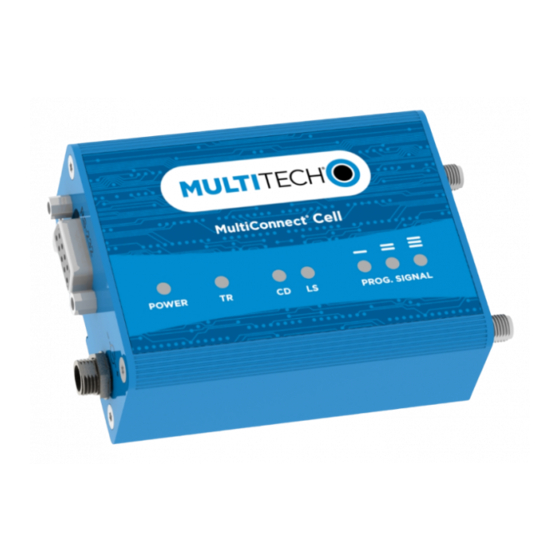
Page 6: Chapter 1 - Product Overview
It is intended for use in energy, utility, or industrial settings. The MTC-LAT1 is available with RS-232 and optional GPS connector, or as a USB to Cellular device. Documentation The following documentation is available at https://www.multitech.com/brands/multiconnect-cell-100-series Select your model to get the documentation for that device. Document Description... -
Page 7: Dimensions
PRODUCT OVERVIEW Dimensions Serial ® MultiConnect Cell MTC-LAT1 User Guide... -
Page 8: Serial With Gps
PRODUCT OVERVIEW Serial with GPS ® MultiConnect Cell MTC-LAT1 User Guide... -
Page 9: Usb
PRODUCT OVERVIEW ® MultiConnect Cell MTC-LAT1 User Guide... -
Page 10: Descriptions Of Leds
PRODUCT OVERVIEW Descriptions of LEDs The top panel contains the following LEDs: Power and Terminal Ready LEDs—The Power LED indicates that DC power is present and the TR LED indicates when the unit is ready to receive data. Modem LEDs—Two modem LEDs indicate carrier detection and link status. Signal LEDs—Three signal LEDs display the signal strength level of the wireless connection. -
Page 11: Side Panels
PRODUCT OVERVIEW Side Panels The device has connectors on either side. The figures that follow show the side panels. Serial Serial with ® MultiConnect Cell MTC-LAT1 User Guide... -
Page 12: Mtc-Lat1 Specifications
PRODUCT OVERVIEW Note: The power-saving switch—which appears with the NORMAL and LOW POWER labels—is included only on models that have a serial connector. MTC-LAT1 Specifications Category Description General Standards LTE 3GPP Release 9 HSPA+ 21/GPRS fallback USB interface is CDC-ACM compliant TCP/IP Functions FTP, SMTP, SSL, TCP, UDP Frequency Bands... - Page 13 PRODUCT OVERVIEW Category Description Power Requirements Operating Voltage Serial Models: 5-32 VDC USB Models: 5 VDC Category Description Point-to-Point messaging Mobile-Terminated SMS Mobile-Originated SMS Certifications and Compliance EMC Compliance FCC Part 15 Class B Radio Compliance FCC Part 22, 24, 27 Safety Compliance UL 60950-1 2nd ED cUL 60950-1 2nd ED...
-
Page 14: Rs-232 9-Pin Female Connector
PRODUCT OVERVIEW RS-232 9-Pin Female Connector Abbreviation Description In/Out Carrier Detect Receive Transmit Data Terminal Ready Ground Data Set Ready Request to Send Clear to Send Ring Indicator Power Measurements Multi-Tech Systems, Inc. recommends incorporating a 10% buffer into your power source when determining product load. -
Page 15: Serial Model With Gps: Mtc-Lat1-B02 Power Draw
PRODUCT OVERVIEW Radio Sleep mode Sleep mode Cellular call Average Average TX Total inrush Total inrush Protocol current, current, measured pulse charge, in charge connected to connected to connection, current amplitude millicoulomb duration wireless live network, no data (milliamps) current s (mC) during (milliamps) -
Page 16: Usb Model: Mtc-Lat1-B03 Power Draw
PRODUCT OVERVIEW USB Model: MTC-LAT1-B03 Power Draw Radio Sleep mode Cellular Average Average TX pulse Total inrush Protocol current connection idle, measured current amplitude current charge in (milliamps) no data (milliamps) at (milliamps) millicoulombs (milliamps) maximum power (mC) 5 Volts GSM 850 23.1 1080... -
Page 17: Chapter 2 - Safety Warnings
SAFETY WARNINGS Chapter 2 – Safety Warnings Radio Frequency (RF) Safety Due to the possibility of radio frequency (RF) interference, it is important that you follow any special regulations regarding the use of radio equipment. Follow the safety advice given below. Operating your device close to other electronic equipment may cause interference if the equipment is inadequately protected. -
Page 18: Antenna
SAFETY WARNINGS Antenna The antenna intended for use with this unit meets the requirements for mobile operating configurations and for fixed mounted operations, as defined in 2.1091 and 1.1307 of the FCC rules for satisfying RF exposure compliance. If an alternate antenna is used, consult user documentation for required antenna specifications. ®... -
Page 19: Chapter 3 - Installing And Using The Device
INSTALLING AND USING THE DEVICE Chapter 3 – Installing and Using the Device Installing the Device Connect suitable antenna(s) to the antenna connector(s). If your device is the serial version: Connect the DE9 male connector (9-pin) of the RS-232 cable to the RS-232 connector on the device, then connect the other end to the serial port on the other desired device. -
Page 20: Usb Cable Recommendations
If possible, use a USB port that connects directly to the motherboard rather than a USB port with added cabling inside the computer chassis. Use USB 3.0 ports if available. These ports are typically rated for more current. You can order the USB cable through MultiTech. The part number is CA-USB-A-MINI-B-3 Powering Down Your Device CAUTION: Failing to properly power down the device before removing power may corrupt your device's file system. -
Page 21: Removing A Sim Card
Some environments are harsher on particular bands. MultiTech products have antenna connectors at the best spacing for the product size. Placing antennas in close proximity to each other is not optimal, but you can do it if necessary. It depends on the signal strength to and from each antenna. -
Page 22: Antenna Approvals And Safety Considerations
All antennas need to have a minimum flammability rating. Safety requirements depend on your final product. Unless otherwise noted, antennas certified by MultiTech are not approved for outdoor use. Do not extend these antennas outside of any building. Diversity and Power Draw There are no significant power draw differences. -
Page 23: Chapter 4 - Antenna And Activation Information
The cellular radio portion of the device is approved with the following antenna or for alternate antennas meeting the given specifications. Manufacturer: EAD Ltd. Description: LTE Antenna with SMA-Male Connector Model Number: WTR7270 MultiTech Part Number: 45009760L MultiTech ordering information: Model Quantity ANLTE3-2HRA ANLTE3-10HRA ANLTE3-50HRA... -
Page 24: Gps Antenna Specifications
Account Activation for Cellular Devices Some MultiTech devices are pre-configured to operate on a specific cellular network. To use the device, you must set up a cellular data account with your service provider. Each service provider has its own process for adding devices to their network. -
Page 25: Chapter 5 - Configuring And Communicating With Your Device
CONFIGURING AND COMMUNICATING WITH YOUR DEVICE Chapter 5 – Configuring and Communicating with Your Device Interacting with Your Device Overview This section describes how to use AT commands to interact with your device. Using terminal software such as Kermit, you can issue AT commands to communicate with and configure your modem. The AT commands let you establish, read and modify device parameters and help you control how the device operates. -
Page 26: Verifying Signal Strength
CONFIGURING AND COMMUNICATING WITH YOUR DEVICE Data bits: 8 Parity: none Stop bit: 1 Flow control: hardware To confirm communication with the device: Type AT and press Enter. If the device responds with OK, it is properly communicating. Verifying Signal Strength To verify the device signal strength, enter: AT+CSQ The command indicates signal quality, in the form:... -
Page 27: Example
CONFIGURING AND COMMUNICATING WITH YOUR DEVICE Note: Signal strength of 10 or higher is needed for successful packet data sessions. Example A example response to AT+CSQ: +CSQ: 15,1 Checking Network Registration Before establishing a packet data connection, verify the is device registered on the network. To do this enter the network registration report read command: AT+CREG? If the device returns:... -
Page 28: Configuring Device As Udp Listener To Accept Udp Client Connections
CONFIGURING AND COMMUNICATING WITH YOUR DEVICE To close Socket 1, enter: AT#SH=1 The device responds with OK. To close the data connection: Enter: AT#SGACT=1,0 The device responds with OK. Configuring Device as UDP Listener to Accept UDP Client Connections To configure the device as a UDP client: Check signal strength. -
Page 29: Configuring Device As Udp Client To Connect To Udp Server
CONFIGURING AND COMMUNICATING WITH YOUR DEVICE Exit Data Mode and Close Connection To exit data mode and close the socket: Enter the escape sequence: To close Socket 1, enter: AT#SH=1 The device responds with OK. To close the data connection, enter: AT#SGACT=1,0 The device responds with OK. -
Page 30: Transferring Ftp File To Ftp Server
CONFIGURING AND COMMUNICATING WITH YOUR DEVICE AT#SH=1 The device responds with OK. To close the data connection, enter: AT#SGACT=1,0 The device responds with OK. Transferring FTP File to FTP Server To connect to FTP server and upload files: Check signal strength. Enter: AT+CSQ Activate context one... -
Page 31: Downloading File From Ftp Server
CONFIGURING AND COMMUNICATING WITH YOUR DEVICE AT#FTPCLOSE Close the PPP data connection. Enter: AT#SGACT=1,0 The device responds with OK. Downloading File from FTP Server To connect to an FTP server and download files: Check signal strength. Enter: AT+CSQ Activate context one Enter: AT#SGACT=1,1 Set FTP operations timeout to 10 seconds... -
Page 32: Reading, Writing And Deleting Messages
CONFIGURING AND COMMUNICATING WITH YOUR DEVICE AT#FTPCLOSE Close the PPP data connection. Enter: AT#SGACT=1,0 The device responds with OK. Reading, Writing and Deleting Messages Reading Text Messages To read a text message in text mode: Put the device in text mode. Enter: AT+CMGF=1 Read message. -
Page 33: Deleting Messages
CONFIGURING AND COMMUNICATING WITH YOUR DEVICE AT+CMGF=1 AT+CMGS="0001112222" > How are you? <CTRL+Z to send> +CMGS: 255 Where 0001112222 is the phone number. Deleting Messages To delete one text message, enter: AT+CMGD=I,# where I is the index in the select storage and # is the delflag option. Enter: Deletes message in the specified index. -
Page 34: Chapter 6 - Regulatory Information
REGULATORY INFORMATION Chapter 6 – Regulatory Information Industry Canada Class B Notice This Class B digital apparatus meets all requirements of the Canadian Interference-Causing Equipment Regulations. Cet appareil numérique de la classe B respecte toutes les exigences du Reglement Canadien sur le matériel brouilleur. -
Page 35: Fcc Interference Notice
2015/863 of the European Parliament (Restriction of the use of certain Hazardous Substances in electrical and electronic equipment - RoHS). These MultiTech products do not contain the following banned chemicals Lead, [Pb] < 1000 PPM Mercury, [Hg] <... -
Page 36: Information On Hs/Ts Substances According To Chinese Standards
REGULATORY INFORMATION Information on HS/TS Substances According to Chinese Standards In accordance with China's Administrative Measures on the Control of Pollution Caused by Electronic Information Products (EIP) # 39, also known as China RoHS, the following information is provided regarding the names and concentration levels of Toxic Substances (TS) or Hazardous Substances (HS) which may be contained in Multi-Tech Systems Inc. -
Page 37: Information On Hs/Ts Substances According To Chinese Standards (In Chinese)
REGULATORY INFORMATION Information on HS/TS Substances According to Chinese Standards (in Chinese) 依 依 照 照 中 中 国 国 标 标 准 准 的 的 有 有 毒 毒 有 有 害 害 物 物 质 质 信 信 息 息 根据中华人民共和国信息产业部... -
Page 38: Chapter 7 - Using Connection Manager
Click Connection Manager. Open or unzip the Connection Manager file and run the installer (.msi file). In the MultiTech Connection Manager Setup Wizard, read the end-user license agreement and check I accept the terms in the License Agreement. Click Next to have the installer automatically disable the native WWAN AutoConfig service in Windows. -
Page 39: Setting Up A Serial Device In Windows Device Manager
To specify a folder for Connection Manager, use the default folder or click Change to browse to the folder you want to use. Click Install. A separate wizard opens for installing Telit drivers. Some MultiTech devices use embedded modules from Telit Wireless Solutions to provide cellular connectivity; these devices require Telit drivers. Select Complete setup type. - Page 40 USING CONNECTION MANAGER In the Add Hardware Wizard: Click Next. Select Install the hardware that I manually select from a list, then click Next. Select Modems, then click Next. Check Don't detect my modem; I will select it from a list, then click Next. Select Standard Modem Types, then select Standard 33600 bps Modem on the right.
-
Page 41: Connecting A Device
USING CONNECTION MANAGER Connecting a Device Before You Begin Make sure that your device is connected to the computer where Connection Manager is installed. Set up the device in Device Manager. Refer to Setting Up a Serial Device in Windows Device Manager. -
Page 42: Uninstalling Connection Manager
The steps above describe how to uninstall Connection Manager using Control Panel. You can also uninstall the application by using the installer file (.msi). Double-click the file, in the MultiTech Connection Manager Setup Wizard, click Next, and then select Remove on the next two pages. -
Page 43: Main Tab
USING CONNECTION MANAGER Connection Details Terminal Charts Main tab The Main tab displays the following: Status of device connection: Searching, Connecting, Connected, Disconnecting, or Disconnected The action button, which changes according to the current device connection status: Detect, Connect, or Disconnect Signal strength bars and percentage indicator (only when connection to the carrier's network is established) Note:... -
Page 44: Settings Tab
USING CONNECTION MANAGER Settings tab Use the Settings tab to specify the type of device: USB Modem or Serial Modem. If USB Modem is selected, the tab displays USB settings. These settings cannot be edited. If Serial Modem is selected, the tab displays the serial settings that match the serial-port settings for the device. - Page 45 USING CONNECTION MANAGER Try the following steps: Click the Settings tab and make sure that the appropriate modem type is selected: USB or Serial. If you are connecting a serial device, make sure that all serial modem settings correspond to the serial modem and serial port configuration.
Need help?
Do you have a question about the MultiConnect MTC-LAT1-B02 and is the answer not in the manual?
Questions and answers