Table of Contents
Advertisement
Advertisement
Table of Contents

Related Manuals for GST GST-IFP8


Summary of Contents for GST GST-IFP8
- Page 1 GST-IFP8 USER MANUAL...
- Page 2 This instructions covered in this manual have been carefully checked for accuracy and are presumed to be correct. However, the manufacturer assumes no responsibility for inaccuracies and reserves the right to modify and revise this document without notice. This manual covers the installation, programming and commission of the GST IFP8 Fire Alarm Control Panels.
-
Page 3: Table Of Contents
Contents Preface EN 54 Information ......................... 4 Introduction ............................5 Installation ............................6 System Lay-out ........................... 8 Main Power Lay-out ..........................9 Main Control Board .......................... 10 Terminal Connection ........................10 Device Addressing ..........................11 Control Panel and Indication ...................... -
Page 4: Preface En 54 Information
Preface EN 54 Information The GST IFP8 is an Intelligent Fire Alarm Control Panel complies with the latest requirement of EN standard. GST-IFP8 Intelligent Fire Alarm Control Panel (FACP) complies with the requirements of EN 54-2 1997 + A1: 2006 and EN 54-4 1997 + A1: 2002 + A2: 2006. -
Page 5: Introduction
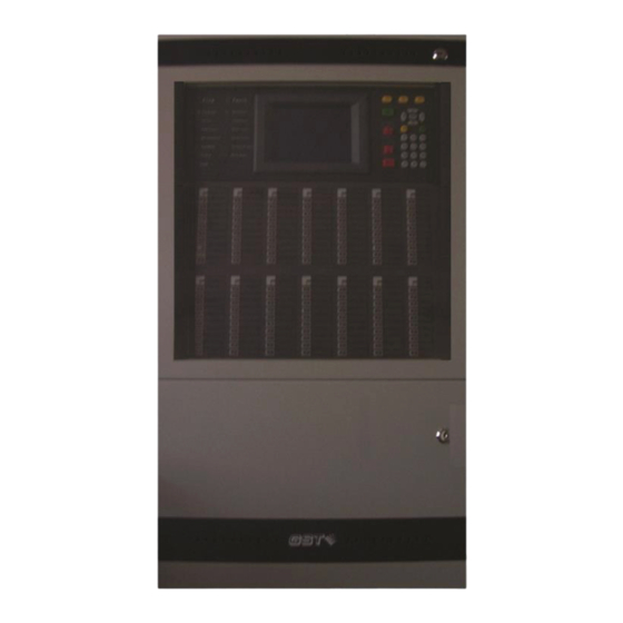
Introduction The GST-IFP8 is an intelligent fire alarm control panel. Flush-mounted type housing it provides the perfect solution for all medium to large system by utilizing advance GST Protocol. The system is compatible with the complete range of GST Intelligent detectors, Sounders, Call Points, and Interfaces, including intrinsically safe and gaseous extinguishing control. -
Page 6: Installation
Install lation Installatio on of the pa anel should be carried out by train ed personn el only. The e electronic components inside th he panel are e vulnerable to damage by electros static discha arges. It is re ecommende ed to wear a wrist stra ap designed... - Page 7 Locate and placed the panel and marked the three holes for mounting.
-
Page 8: System Lay-Out
System Lay-out Main Control Board Main Indication Board Main Power Board AC Filter Power Switch AC/DC Power Converter Zone Indication Board Printer... -
Page 9: Main Power Lay-Out
Maximum Charge Voltage: 27.3V±0.3V Type: Sealed lead acid batteries Maximum Charge Capacity: Two 12V/38Ah batteries Recommended manufacturer and model of battery: Yuasa NP38-12I Maximum Internal Resistance: 0.7Ω Quiescent Current under Full-loaded Condition: 1.4A Maximum Operating Current: 4.2A Recommended Cable: GST fire cable... -
Page 10: Main Control Board
Main Control Board Warning: Use static precautions when handling boards, grounding wrist strap and contact with chassis. Setting the card address Numbering sequence, lower card recommended lowest numerical setting. Set dials on the additional board in ascending order. Each card must be set at least one higher digit than the lower card. -
Page 11: Device Addressing
Recommended Cable length: 1000 meters Recommended Cable: GST Fire Cable Loop protection: Optional loop isolator (C- 9503/4) Device Addressing The device address can be programmed manually through handheld programmer (P-9910B) or can be changed in the control panel. The address of the device is recommended to be consecutive number but not limited in order to have flexibility and should not be repeated. - Page 12 Description: Device Alarm Stop – via Output Condition Disable CE Mode Delay Time Number (Default) Silence Button Alarm Routing A 00000083 Immediate Routing Output to Sounder A 00000082 Immediate Sounder Output to FPE A 00000081 Immediate FEED BACK: Feedback signal input for alarm routing devices. It gives fault signal when connecting line is shorted or opened.
-
Page 13: Control Panel And Indication
Contro ol Panel and Indi ication Descript tion of LED Indicato olour Descriptio w to clear Display: This provides s the message e of the event ts and system status. Fire When illumina ated it indicate t that a FIRE has s been Attend d the condition... -
Page 14: Description Of Controls
When illuminated it indicates the power supply is Power GREEN present Correct the alarm condition then SILENCE YELLOW When illuminated it indicates that the SILENCE perform the panel rest. Note: If there button has been pressed and. a new alarm occurs, the panel will resound again. -
Page 15: Zone Indication Panel
Zone Indication Panel Every FACP comes with two zone indication panels, appearance of which is shown in Fig. 3-4. On the indication panel, each unit consists of two indicators and a label. The user can put the name of device on the right of the indicators. Indicators Colour Description... -
Page 16: System Commissioning
System Commissioning Commission Mode The control panel should be set to commissioning mode in order to have a full access in any programming menu of the system. To set the control panel in or out of commissioning mode: • Press the SYSTEM SETUP button, input the management password, no default password just press Enter •... -
Page 17: How To Check Duplicated Address And Device Mismatch
How to check duplicated address and device mismatch To access the duplicated address check and device mismatched the system should be in DIGITAL mode (see the System Initialization). The device mismatch will indicate if given a wrong device type on the actual installed detector. -
Page 18: How To Modify The Device Sensitivity
How to modify the device sensitivity To access modify sensitivity the system should be in DIGITAL mode (see the System Initialization) • Press the SYSTEM SETUP button, input the management password, no default password just press Enter • Then press number 4 button or using the cursor up and down and select 4 Commissioning •... -
Page 19: System Programming
System Programming The control panel should be set to commissioning mode in order to have a full access in any programming menu of the system. How to program the device detail To set the control panel in programming the device detail: •... -
Page 20: How To Program The Zone
How to program the zone To set the control panel in programming the zone • Press the SYSTEM SETUP button, input the management password, no default password just press Enter • Then press number 1 button or using the cursor up and down and select 1 PROGRAMMING •... -
Page 21: How To Program The Equation
How to program the equation To set the control panel in programming the equation • Press the SYSTEM SETUP button, input the management password, no default password just press Enter • Then press the number 1 button or using the cursor up and down and select 6 C&E EQUATION SETUP then press Enter. -
Page 22: How To Edit The Device Type
How to edit the device type To set the control panel in programming the device type • Press the SYSTEM SETUP button, input the management password, no default password just press Enter • Then press the number 1 button or using the cursor up and down and select 7 Device Type Setup then press Enter. -
Page 23: System Browsing
System Browsing To view the control panel programmed • Press the USER SETUP button, input the user password, no default password just press Enter • Then press number 1 button or using the cursor up and down and select 1 BROWSE the press Enter *BROWSE* ***************************************** 1 BROWSE DEVICES... -
Page 24: To View The Zone (Input) Assignment
To view the zone (INPUT) assignment • Press the number 2 button or using cursor up and down and select 2 BROWSE ZONE • Select the loop using arrow cursor up or down and press Enter. Total number of INPUT Total number of OUTPUT Total Number of Total Number of... -
Page 25: To View The Duplicated Address
To view the duplicated address The duplicated address check under commissioning menu must be enabled first before viewing the address and the location of the loop. To view the duplicated address on the control panel. • Press the number 2 button or using cursor up and down and select 4 Browse Duplicated Address •... -
Page 26: To View The System History
To view the system history The history memory is divided in two parts FIRE HISTORY which stored only fire event and COMMON HITORY for different types of system event except fire. Both have the 999 event capacity in non-volatile memory To view the events in the control panel: •... -
Page 27: To Set-Up The Local Outputs
To set-up the local outputs This set-up allows the 3 on-board output circuits to delayed and placed in one or more alarm. • Press the SYSTEM SETUP button, input the system password, no default password just press Enter • Then press number 2 button or using the arrow cursor up and down and select 2 Local Output Setup then press Enter. -
Page 28: System Operation
SYSTEM OPERATION Dependency Mode/ Pre-alarm The signal from an automatic fire detection device selected for positive alarm sequence operation shall be acknowledged at the fire alarm control unit by a trained personnel within given time of annunciation in order to initiate the alarm investigation phase. -
Page 29: Test Mode
*Day Mode Pre-alarm Window: programmable from 1 sec. to 30 min. A distinctive pre-alarm indication shall be displayed. Alarm Verification window: programmable from 1 sec. to 30 min. *Night Mode (Default setting) Pre-alarm Window: preprogrammed 30 min. Auto-reset the Alarm in the Panel after 30 min (Type A) Pre-alarm Window: preprogrammed 5 min. -
Page 30: Disable/Enable Option
DISABLE/ENABLE OPTION Any or group of device registered onto the control panel can disable by manual operation by entering the zone number, address and device type. To set the panel into test mode • Press the USER SETUP button, input the user password, no default password just press Enter •... -
Page 31: Maintenance
Maintenance The FACP shall only be repaired by specially trained GST technical service personnel. Please disconnect the power before repair! Warning: The key to the FACP shall be kept by specially assigned maintenance personnel! Replacing the Battery Type of battery: Sealed lead-acid battery... -
Page 32: System Menu
System Menu System Setup 1 PROGRAMMING 1 Point-Setup: loop 01 point (1-242) Zone (1-999): Device Type: Attribute (0-6): Text (40 byte): 2 Zone Setup: (I-999) (Select the zone) Dependency type (0-2) 0 – Off 1 – Type A 2 – Type B Sounder Mode (0-1) 0 –... - Page 33 2. LOCAL OUTPUT SETUP Sounder A Mode (0-2) 0-one fire 1-more fire 2-On C&E FPE A Mode (0-2) 0-one fire 1-more fire 2-On C&E Alarm Routing A mode (0-2) 0-one fire 1-more fire 2-On C&E Delay Time: 00 (note: ratio 1:10) 3.
- Page 34 User Setup 1 BROWSE 1 Browse Devices: View the number of devices per loop and detailed provided with each device 2 Browse Zone: View the total number of Input devices per zone 3 Browse Group: View the total number of Output devices per group (Zone) 4 Browse Duplicated Address : View the repeated address in a loop 5 Browse Panel Status: View the panel configuration and version 6 Browse Event and Command: C&E or Sequence of operation detailed...
- Page 35 7 START/STOP DEVICE 1 Start Device 2 Stop Device By device code- Zone, address, device type 8 DISABLE/ENABLE 1 Dis/Enable Devices – By Code 1 Disable Device 2 Enable Device 2 Dis/Enable Device – By Address 1 Disable Device 2 Enable Device 2 Dis/Enable Zone 1 Disable Zone 2 Enable Zone...
-
Page 36: Lists Of Device Type And Condition
Lists of Device Type and Condition DEVICE CONDITON DEVICE TYPE NUMBER RELAY Undefine 0 MULTISENSOR 1 HEAT DETECTOR 2 OPTICAL SMOKE 3 USER DEFINED 4 GAS DETECTOR 5 FIRE BEAM DETECTOR 6 FLAME DETECTOR 7 CONVENTIONAL P 8 USER DEFINED 9 ... - Page 37 USER DEFINED 38 Net Unit 39 Repeator 40 ZONE VALVE 41 FLOW SWITCH 42 PRESSURE SWITCH 43 USER DEFINED 44 USER DEFINED 45 SUPERVISORY USER DEFINED 46 USER DEFINED 47 USER DEFINED 48 USER DEFINED 49 USER DEFINED 50 USER DEFINED ...
- Page 38 ALARM ROUTINGA 83 Loop Flash Data 84 Undefine 85 Panel charger 86 BAT Resistance 87 Undefine 88 Undefine 89 Undefine 90 Undefine 91 Undefine 92 Undefine 93 Undefine 94 Undefine 95 Undefine 96 ...
-
Page 39: Operation Following An Alarm Or Fault Condition
Operation Following an Alarm or Fault Condition FIRE Alarm Tone and Red LED Fire Sum:001 001: 13 Jan 10:01 Zone 001 Sum001/002 [√] Second Floor →Press [Enter] to view details →Press [L/R Scroll] to switch inf. type Last Fire: 13Jan 10:01 Zone001 [√]... - Page 40 FAULT Alarm Tone and Yellow LED Fault Sum:001 001: 13 Jan 10:01 Zone 001 Sum001/002 [√] Second Floor →Press [Enter] to view details FAR:OK FPE:OK OTS:OK 10:20:01 1. Open the door. LCD screen displays: The first, and in multiple alarm condition also the last fault, time and zone location.
- Page 41 Tel: +44 1283 225 478 Fax: +44 1283 220 690 Email: info@gst.uk.com www.gst.uk.com Global System Technology PLC PO Box 17998 Unit ZA04 JEBEL ALI Free Zone, Dubai, UAE Tel: +971 (0) 4 8833050 Fax: +971 (0) 4 8833053 Email: info@gst.uk.com www.gst.uk.com...
Need help?
Do you have a question about the GST-IFP8 and is the answer not in the manual?
Questions and answers