
Subscribe to Our Youtube Channel
Related Manuals for StewMac ’64 REVERB UNIT


Summary of Contents for StewMac ’64 REVERB UNIT
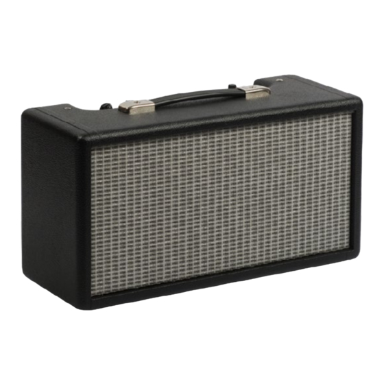
- Page 1 ’64 REVERB UNIT O R I G I N A L 6 G 1 5 C I R C U I T Reverb you can't get from a pedal. A S S E M B LY I N S T R U C T I O N S With loads of helpful tips!
-
Page 2: Table Of Contents
COPYRIGHT WARNING This material is protected by copyright and has been created by and solely for the purposes of StewMac . You may not sell, alter or further reproduce any part of this material, or distribute it to any other per- son . -
Page 3: About This Iconic Reverb Unit
Follow our steps closely for safety, too: we’ve carefully laid out a path that even newcomers can follow in handling electrical components . Building an electronics kit can seem daunting, but nobody makes it easier than StewMac . Watch for helpful tips along the way, too—we’re here to help! Let’s get building! stewmac.com... -
Page 4: How To Build This Kit
+120 POWER TRANSFORMER 125A12A +130 To tube heaters and pilot light +295 +300 AC SWITCH FUSE 1 amp slow-blow #10733 © 2018 StewMac Resistor Capacitor Electrolytic Cap. Potentiometers Diode Transformer Jack Ground Shielded Preamp tube Power tube Rectifier tube ’64 REVERB UNIT... -
Page 5: Parts List
(4) 4-40 machine screw, 1/4" (1) Capacitor pan (6) 4-40 locknut (1) Chassis (4) Self-tapping screw (1) Black wood screw (2) Eyelet boards (1) Power cord clamp (2) Insulator boards (1) Strain relief for power cord (6) Rubber grommet stewmac.com © 2018 StewMac... - Page 6 (1) 100K control pot (L-linear taper) (1) Reverb wiring kit (shielded wire and 4 RCA plugs) (2) 250K control pot (L-linear taper) (3) Knob (1) Three-lug terminal (1) Four-lug terminal (1) Power switch (1) Power cord stewmac.com © 2018 StewMac...
-
Page 7: Tools And Supplies
Drill with a 5/32" bit 5/32" for mounting eyelet board to chassis #3000 Guitar Tech Ruler Screwdriver Set Item #4905 StewMac Shop Rule Digital multimeter Item #3618 Fieldpiece Pocket Multimeter #1606 Snuffer stick (bleed resistor) Wire Stripper Item #1552 Snuffer Stick... -
Page 8: Amp Voltages Are Seriously Dangerous
To discharge a capacitor, clip the snuffer stick lead to ground—preferably a mounting bolt on the power transformer . Hold the tip of the stick to the cap’s positive lead and use your multimeter to watch the voltage drain to less than 18V . stewmac.com © 2018 StewMac... -
Page 9: How To Read Resistor Values
Installing capacitors with the polarity backwards will make the circuit malfunction and quickly destroy the capacitor— even causing it to explode . x1,000 +/- 5% +/- 5% Blue Gray Orange Gold K = 1,000 Read this band first (closest to an end) stewmac.com © 2018 StewMac... -
Page 10: Complete Wiring Diagram
Our diagrams one step at a time . show a flat Your circuit-building skills will get stronger with each step! view of the metal chassis stewmac.com © 2018 StewMac... -
Page 11: Prepping The Cabinet
3/8" of the internal to mark the depth, or use a StewMac cloth shielding . Insert the exposed Depth-stop Drill Bit (item #1712) . -
Page 12: Prepping The Boards
The main board will be mounted inside the chassis, and the filter cap board will be mounted on the outside . In the photo above, we’ve positioned the empty boards just to show their eventual mounting locations . stewmac.com © 2018 StewMac... -
Page 13: Installing The Chassis-Mounted Components
240V: black/red striped transformer is mounted, but make sure the grommets do not pull out of In North America for example, you their holes . would twist the white wire together with the black wire for 120V . stewmac.com © 2018 StewMac... - Page 14 . These jacks are for of the chassis . Mount the modified the reverb in, reverb out, and the three-lug grounding strip under the footswitch . front locknut . stewmac.com © 2018 StewMac...
- Page 15 . Install the pilot lamp socket Mount the pilot lamp socket by screw- ing the lens from the outside into the socket assembly . Position the socket so the tabs are facing up for soldering . stewmac.com © 2018 StewMac...
- Page 16 . Wrap the other lead of this cap and solder the black lead to the left connection yet . through the middle lug of the tone lug on the power switch . pot . Solder both leads in place . stewmac.com © 2018 StewMac...
- Page 17 . makes them a safe place to anchor these unused live wires . The remain- ing lug on this strip is grounded to the chassis, and will be used later to ground the power cord . stewmac.com © 2018 StewMac...
- Page 18 Solder the connection to the center eyelet board later on . Assume there's a mistake and lug of the footswitch jack along with you’re the one who’ll find it. the jumper from socket V1 . stewmac.com © 2018 StewMac...
-
Page 19: How To Wrap And Solder The Eyelet Board
Also tin component leads like multi- is shiny—a sign that it was left to cool when you strip away about 1/4" of the strand wires to help the solder flow . undisturbed . cloth wrap . stewmac.com © 2018 StewMac... -
Page 20: Filter Cap Eyelet Board
B . Add another 22μF electrolytic cap with the positive lead through eyelet G and the negative through eyelet C . Wrap a third 22μF electrolytic cap between eyelets H (positive lead) and D (negative) . stewmac.com © 2018 StewMac... -
Page 21: Main Eyelet Board
9 . Wrap the resistor's other lead Connect a 3-1/2" white jumper to tween eyelets 10 and 38 . onto eyelet 8 . eyelet 32 . Add a 3" green jumper to eyelet 14 . stewmac.com © 2018 StewMac... - Page 22 36 . 17 and pull it tight to keep it in place . Flip the board over and add a 2-3/4" green jumper between the back of eyelet 8 and the back of eyelet 14 . stewmac.com © 2018 StewMac...
- Page 23 Add a 100K resistor between eyelets 4 and 5 . 13 and 34 . Add a 1 .5K resistor between eyelets Add a .0022μF Orange Drop cap be- 4 and 21 . tween eyelets 5 and 34 . stewmac.com © 2018 StewMac...
- Page 24 1 and 2 . Add the work, make sure through the bottom of hole 28 and second between eyelets 18 and 24 . every connection pull it tight to keep it in place . is tight! stewmac.com © 2018 StewMac...
-
Page 25: Soldering And Installing The Eyelet Boards
4-40 locknut . jack . stewmac.com © 2018 StewMac... -
Page 26: Connecting The Eyelet Board To The Chassis Components
Trim all excess wire ends and inspect Wrap the white jumper from hole 30 your solder joints . through pin 2 of socket V2 and solder in place . Trim all excess wire ends and inspect your solder joints . stewmac.com © 2018 StewMac... - Page 27 Coming through the grommeted hole near the back wall of the chassis will be the black filter choke leads . Solder one of these leads to eyelet 1 and solder the other lead to eyelet 18 . stewmac.com © 2018 StewMac...
- Page 28 Next you’ll install the Trim the excess wires . wires that power the heating elements in the tubes . That part’s a little tricky, so review the following page carefully before you start on it . stewmac.com © 2018 StewMac...
-
Page 29: Installing The Heater Wires
. Twisted bending them . This keeps the wires are easier to route away heater wires from mingling from signal wires . with the signal wires . stewmac.com © 2018 StewMac... - Page 30 . them at a 90° angle toward socket V1 . Twist the other ends of 1” untwisted Trim the excess wire . jumpers together . stewmac.com © 2018 StewMac...
- Page 31 . The strain relief is a tight fit . Use pliers to squeeze it onto the power cord out- side the chassis, and keep squeezing to fit it into the mounting hole . stewmac.com © 2018 StewMac...
-
Page 32: Completed 6G15 Wiring
© 2018 StewMac... -
Page 33: Final Assembly
. The next page is Make sure the socket cap is secure . going to keep you Never use a fuse rated above 1 amp in this unit . out of trouble! stewmac.com © 2018 StewMac... -
Page 34: Testing And Troubleshooting
2 for your B+ voltage . This should be roughly 420V DC . Unplug the unit . Danger: Remember to discharge the capacitors before working on the circuit. See how to use a snuffer stick on page 6 . stewmac.com © 2018 StewMac... - Page 35 23 . StewMac is here to help! your reverb cables again for a short . For more than fifty years, StewMac If all of these voltages come within If the unit squeals or seems unstable,...
-
Page 36: Learning More: Secrets Revealed In The Schematic
This then passes through a series of three large electrolytic capacitors which filter out the pulsing to create a smooth current . As each cap smoothes a bit more, the current is also passing through resistors that lower the voltage . stewmac.com © 2018 StewMac... -
Page 37: 6G15 Circuit Schematic
© 2018 StewMac... - Page 38 . It’s all here: clarity, distortion, and rectifier tube sag . D I F F I C U LT Y H O U RS : #10737 22 WATTS / 12" SPEAKER / ORIGINAL AB763 CIRCUIT stewmac.com © 2018 StewMac...
- Page 39 This isn't a pocket-sized digital simulation; this is the real deal! Listen to Dick Dale’s “Misirlou” while doing this easy build . D I F F I C U LT Y #10733 ORIGINAL 6G15 CIRCUIT H O U RS : stewmac.com © 2018 StewMac...
- Page 40 © 2018 StewMac...
-
Page 41: Tube Replacement Chart
O R I G I N A L 6G 1 5 C I R C U I T I C O N K I T S DANGER: Unplug the unit before changing tubes. Tube locations from left to right: 12AT7 12AX7 (ECC81) (ECC83) Use only 1-amp slow-blow fuse. #10733 stewmac.com © 2018 StewMac... - Page 44 StewMac tools + ideas for guitarmaking 21 N . Shafer St ., Athens, OH 45701 800-848-2273 stewmac .com ©2018 StewMac . All rights reserved . #i10733 Updated December, 2018...
Need help?
Do you have a question about the ’64 REVERB UNIT and is the answer not in the manual?
Questions and answers