
Related Manuals for StewMac ’57 MINI TWEED


Summary of Contents for StewMac ’57 MINI TWEED
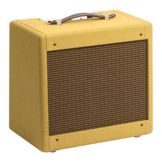
- Page 1 ’57 MINI TWEED C O M B O A M P K I T O R I G I N A L 5 F 1 C I R C U I T One-knob titan of tone. A S S E M B LY I N S T R U C T I O N S With loads of helpful tips!
-
Page 2: Table Of Contents
COPYRIGHT WARNING This material is protected by copyright and has been created by and solely for the purposes of StewMac . You may not sell, alter or further reproduce any part of this material, or distribute it to any other per- son . -
Page 3: About This Iconic Amp
. These artists include Joe Walsh and Eric Clapton (listen to “Layla” while you build this kit!) . StewMac ICON KITS bring classics that are no longer made, or are simply unaffordable, within reach . And the best part is you get to build them with your own hands . -
Page 4: How To Build This Kit
See how your guitar’s signal gets processed into sound Power page 10K 2W Power AC switch 1 amp slow-blow fuse 5Y3 GT To tube heaters and pilot light #10730 © 2018 StewMac Resistor Capacitor Potentiometer Transformer Jack Ground Diode tube Triode tube Pentode tube ’57 TWEED 5W... -
Page 5: Parts List
(2) 4-40 machine screw, 1/4" (1) Insulation board (6) 4-40 locknut (1) Black wood screw (1) 4Ω, 8" speaker (1) Strain relief for power cord (1) Cable clamp for power cord (2) Rubber strain relief grommet stewmac.com © 2018 StewMac... - Page 6 Wire (1) Control pot with switch (1M) (1) Yellow wire (1) Green wire (1) Chicken head knob (1) Speaker wire (two leads) (2) Three-lug ground terminal (1) Power cord Transformers (1) Power transformer (1) Output transformer stewmac.com © 2018 StewMac...
-
Page 7: Tools And Supplies
#3000 Guitar Tech 3/16" for mounting chassis to cabinet Screwdriver Set 5/32" for mounting eyelet board to chassis Ruler Item #4905 StewMac Shop Rule #1606 Digital multimeter Wire Stripper Item #3618 Fieldpiece Pocket Multimeter Snuffer stick (bleed resistor) Item #1552 Snuffer Stick Copper shielding tape Item #0028 2"... -
Page 8: Amp Voltages Are Seriously Dangerous
To discharge a capacitor, clip the snuffer stick lead to ground—preferably a mounting bolt on the power transformer . Hold the tip of the stick to the cap’s positive lead and use your multimeter to watch the voltage drain to less than 18V . stewmac.com © 2018 StewMac... -
Page 9: How To Read Resistor Values
Installing capacitors with the polarity backwards will make the circuit malfunction and quickly destroy the capacitor— even causing it to explode . x1,000 +/- 5% +/- 5% Blue Gray Orange Gold K = 1,000 Read this band first (closest to an end) stewmac.com © 2018 StewMac... -
Page 10: Complete Wiring Diagram
. If it looks complex now, don’t worry; we’ll start at the very beginning and do this one step at a time . Your amp-building skills will get stronger with each step! stewmac.com © 2018 StewMac... -
Page 11: Prepping The Cabinet
. Before soldering these leads, place use a StewMac Depth-stop Drill Bit a business card or other protection Drill two 3/16" holes through the (item #1712) . - Page 12 Don’t leave any solder on the outside the wood panel . of the plug tip, or it won’t fit into the jack . This criss-cross pattern keeps the speaker frame flat against the cabinet. Tightening in a circular pattern makes it warp. stewmac.com © 2018 StewMac...
-
Page 13: Prepping The Boards
. Using a sharp pen- eyelets and holes by number . Use a cil through the holes, mark the hole pencil to mark these numbers onto locations onto the insulator board . your eyelet board: stewmac.com © 2018 StewMac... -
Page 14: Installing The Chassis-Mounted Components
8-32 locknuts socket so pin 3 is toward the open side with the large washer on the outside . inside . Mount the two grounding of the chassis . strips at the corners as shown . stewmac.com © 2018 StewMac... - Page 15 . Bend and snap this Don’t solder these connections yet . off, so the pot can mount flush to the surface of the chassis . Mount the pot so its three lugs face out toward the chassis opening . stewmac.com © 2018 StewMac...
- Page 16 3-lug terminal Trim and solder the other black lead to strip along with the green wire from the remaining switch lug on the back the power cord . of the volume pot . stewmac.com © 2018 StewMac...
- Page 17 When everything speaker output jack . green wire to create all the jumpers checks out, you're ready to move on you’re going to need . to the eyelet board . stewmac.com © 2018 StewMac...
-
Page 18: How To Wrap And Solder The Eyelet Board
You should also tin component leads, once . Resoldered joints are messy and to cook out of the joint . like coating multi-strand wires to help more likely to fail . the solder flow for a more solid joint . stewmac.com © 2018 StewMac... -
Page 19: Wrapping Parts Onto The Eyelet Board
8 and 24 . This cap is not polarized, so it can be installed in either direction . Add a 4" yellow jumper to eyelet 8 . stewmac.com © 2018 StewMac... - Page 20 Turn the board over and add a 5" up through hole 23 and pull it tight . eyelet 20 . yellow jumper at eyelet 7 . Run the jumper up through hole 19 and pull it tight so it stays in place . stewmac.com © 2018 StewMac...
- Page 21 3 . Cut a 3/4" piece of wire and remove the insulation . Wrap this between eyelets 2 and 3 . These wires make the ground bus for the three filter capacitors . stewmac.com © 2018 StewMac...
- Page 22 15 . Leave 2-1/2" of lead coming find them now than after soldering! through hole 1 and about 3-1/2" at As you check your work, make sure all hole 15 . the connections are tight . stewmac.com © 2018 StewMac...
-
Page 23: Soldering And Installing The Boards
. you didn’t miss one . Secure it with a lock nut on the out- side of the chassis . Do the same with the second machine screw . stewmac.com © 2018 StewMac... -
Page 24: Installing The Eyelet Board And Insulator Board
(tip connection) of input Solder the jumper from hole 4 to the jack 2 . center lug on the volume pot . Solder the jumper from eyelet 8 to the right lug on the volume pot . stewmac.com © 2018 StewMac... - Page 25 (five wires) . Trim away the ends of short jumper between pins 8 and 1 . 12AX7 socket . the wires . Solder the connections to this socket (eight wires) . Trim away the ends of the wires . stewmac.com © 2018 StewMac...
- Page 26 Wrap the other green jumper from before moving on . the 6V6 socket (from either pin 7 or pin 2) through pins 4 and 5 of the 12AX7 socket, joining those pins in one connection . stewmac.com © 2018 StewMac...
-
Page 27: Final Assembly
Insert the 1-amp fuse into the fuse socket from the front of the chassis . Make sure the socket cap is securely in place . Never use a fuse rated above 1 amp in this amplifier . stewmac.com © 2018 StewMac... -
Page 28: Testing And Troubleshooting
. Once that probe is secured to ground, measure the DC voltage at eyelet 16 . This B+ voltage should be roughly 370V DC . If this reading is correct and the amp continues to behave normally, unplug the amp . stewmac.com © 2018 StewMac... - Page 29 18 to eyelet 14 . StewMac is here to help from the input jacks to the For more than fifty years, StewMac eyelet board has supplied instrument builders from the tube sockets to the...
-
Page 30: Learning More: Secrets Revealed In The Schematic
“grit” part of the amplifier, the first pre-amp tube in the Gain stage . control . We don’t recommend doing this, because it places stress on the output transformer . stewmac.com © 2018 StewMac... -
Page 31: 5F1 Circuit Schematic
© 2018 StewMac... - Page 32 . It’s all here: clarity, distortion, and rectifier tube sag . D I F F I C U LT Y H O U RS : #10737 22 WATTS / 12" SPEAKER / ORIGINAL AB763 CIRCUIT stewmac.com © 2018 StewMac...
- Page 33 This isn't a pocket-sized digital simulation; this is the real deal! Listen to Dick Dale’s “Misirlou” while doing this easy build . D I F F I C U LT Y #10733 ORIGINAL 6G15 CIRCUIT H O U RS : stewmac.com © 2018 StewMac...
- Page 34 © 2018 StewMac...
-
Page 35: Mounting Hole Template
© 2018 StewMac... - Page 36 © 2018 StewMac...
-
Page 37: Tube Replacement Chart
O R I G I N A L 5 F 1 C I R C U I T I C O N K I T S DANGER: Unplug the amp before changing tubes. Tube locations from left to right: 12AX7 Speaker 12AX7 jack (ECC83S) Use only 1-amp slow-blow fuse. stewmac.com © 2018 StewMac... - Page 38 © 2018 StewMac...
- Page 39 © 2018 StewMac...
- Page 40 StewMac tools + ideas for guitarmaking 21 N . Shafer St ., Athens, OH 45701 800-848-2273 stewmac .com ©2018 StewMac . All rights reserved . #i10730 Updated June, 2018...
Need help?
Do you have a question about the ’57 MINI TWEED and is the answer not in the manual?
Questions and answers