Kval 994-X Operation Manual
Pre-hanging door system, includes option rts-fx
Hide thumbs
Also See for 994-X:
- Operation and service manual (188 pages) ,
- Operation manual (130 pages) ,
- Service manual (116 pages)
Table of Contents
Advertisement
Quick Links
Download this manual
See also:
Service Manual
Advertisement
Table of Contents

Subscribe to Our Youtube Channel
Related Manuals for Kval 994-X


Summary of Contents for Kval 994-X
- Page 1 Operation Manual Published: 3/25/2019 Innovation, Quality & Honesty 994-X Pre-Hanging Door System Includes Option RTS-FX...
- Page 2 Proprietary Notice This Manual is confidential and contains proprietary information and intellectual property of KVAL Inc., and is to be used solely by Customer as an operating manual for KVAL Inc. machines. Neither this Manual nor any of the information contained herein may be reproduced or disclosed under any circumstances without the express written permission of KVAL Inc.
- Page 3 KVAL 994-X Operation Manual Your Feedback is Welcome: To help us design products that make your job easier and your business more successful, we'd like to gain your perspective about your user experience with our product - that is, the manual, the machinery, the software, etc.
- Page 4 KVAL 994-X Operation Manual...
-
Page 5: Table Of Contents
Introduction to the 994-X System Chapter 1 Overview of the 994-X Door Hanging System ......1-2 Available Options..................1-3 About this Manual ..............1-6 Safety First!................1-7 Safety Sheet Sign-Off Sheet..............1-7 Safety Terminology of Labels..............1-7 Safety Guidelines..................1-7 Lockout-Tagout Guidelines ............1-11 Follow the P-R-O-P-E-R lockout rule of thumb........1-11... - Page 6 High Frequency Panel ................2-32 Description of the Six Light Panel ........... 2-33 About Sensors ................. 2-34 Quick Start ................2-35 Powering Operations for the 994-X ......... 2-37 How to Power Up the 994-X ...............2-37 Home the 994-X..................2-38 How to Power Down the 994-X............2-38 Emergency Shutdown and Recovery ..........2-39...
- Page 7 Calibration of 994-X Chapter 3 About Calibration ..............3-2 Before you Calibrate ................3-2 Flow Chart of Calibration ..............3-3 About the KVAL Calibration Routine........3-4 Calibration Slot Drilling Specifications ..........3-5 Dimensions of a Calibration Cut ............3-5 Run the Calibration Routine............. 3-6 Select Calibration..................3-6 Select Door Parameters ...............3-6...
- Page 8 Lock Location Calibration ..............3-17 Fast and Slow Lock Plate Timing ............3-18 Option SB: CNC Back Section Calibration .........3-19 994-X Door Hanging System...
- Page 9 CHAPTER 1 Introduction to the 994-X System This chapter provides an overview of the KVAL 994-X Door Hanging System and important safety information to follow when operating the machine. Chapter 1 at a Glance Section Name Summary Page This section provides an overview of the 994-X.
-
Page 10: Overview Of The 994-X Door Hanging System
1-1/2 hp Hi-Frequency spindle motor. The 994-X will accommodate doors with raised molding one or both sides up to 3/4" high, and a minimum of 4" between the raised molding and the edge of the door. -
Page 11: Available Options
Options RT-FX Single Head machine with the Rotary Hopper stand. The Rotary option allows kind change of screw type with preloaded screws. For detailed information about available options, please contact our KVAL Sales and Service department. Option Title Description Option A Six Shooter Gun for 3-1/2'' X To attach 3-1/2"... - Page 12 Light will be mounted on the out-feed end of the 990-F4 that can be seen by the 700-C Assembly Table operator. The light will be on when the door in the 994-X is being machined as a right hand door and off for a left hand door.
- Page 13 Title Description Option Servo Backsection with Cor- The 994-X system combines very high quality hardware ner Squaring detailing, with high speed productivity. Unique features include computer controlled ball screw movements for all router and chisels, complete with square lock face plates.
-
Page 14: About This Manual
Overview of the 994-X Door Hanging System About this Manual About this Manual This manual is part of a package delivered with the machine line. Integration Package includes the following: includes the following: Operation Manual Chapter Title Description Introduction Descriptions of Machine Line and Safety Information. -
Page 15: Safety First
See “Safety Sign-Off Sheet” on page 1-21. Safety Terminology of Labels In addition to the nameplate, KVAL machines may have other warning labels or decals that pro- vide safety information to operators. Safety labels should be clearly visible to the operator and must be replaced if missing, damaged, or illegible. - Page 16 Before performing any mainte- nance or repairs on this machine turn off the main air disconnect. Lockout and tagout this connection. See “Lockout Tagout Procedure” on page 1-12. KVAL 994-X Service Manual...
- Page 17 This should be done in accordance with applicable state and/or federal code requirements. Laser Warnings On some machines, laser indicators are used to set boundaries. Follow the manufacturers safety precautions. KVAL 994-X Service Manual...
- Page 18 Safety First! Compliance with Codes and Regulations KVAL advises that you request an on-site state safety review of your installation of this machine. This is to ensure conformance to any additional specific safety and health regula- tions which apply in your geographic area.
-
Page 19: Lockout-Tagout Guidelines
O..OFF! Shut off all power sources and isolating devices P..Place lock and tag E..ENERGY: Release stored energy to a zero-energy state R ..Recheck controls and test to ensure they are in the “OFF” state KVAL 994-X Service Manual 1-11... -
Page 20: Lockout Tagout Procedure
Turn Switch to the Lock and Tag out Insert Lock into hole. OFF position Note: When multiple people are working on the machine, each person needs to have a lock on the handle in the extra holes provided. KVAL 994-X Service Manual 1-12... -
Page 21: Lockout Tagout Air Supply
The lock and tag can now be removed (only by the person(s) who placed them), and the machine can be re-energized. The tags must be destroyed and the locks and keys returned to the lockout center. KVAL 994-X Service Manual 1-13... -
Page 22: Zero-Energy To Start-Up
Replace Guards Replace all equipment guards. If part of equipment cannot be properly adjusted after start-up with guard on, contact the KVAL Service team. See “Getting Help from KVAL” on page 1-16. Check Controls Confirm that all switches are in the “OFF”... - Page 23 Be sure to follow the P-R-O- P-E-R lockout/tagout procedures, and that those around you do also. Close the Cage Gate Verify all cage gates are securely closed. Ensure all safety protocols are in effect. KVAL 994-X Service Manual 1-15...
-
Page 24: Getting Help From Kval
• Outside the U.S. and Canada, call (707) 762-7367 or fax (707) 762-0485 • Email address is service@kvalinc.com • Hours: 6:00 AM to 4:00 PM Pacific Standard Time, Monday through Thursday 6:30 AM to 1:30 PM Pacific Standard Time, Friday KVAL 994-X Service Manual 1-16... -
Page 25: On-Line Help
Product Return Procedure If you’ve contacted Kval for help and it is determined that a return is necessary, use the procedure below to return the machine or part. Note: Non-Warranty returns are subject to a 15% restocking charge. -
Page 26: How To Download The Service Application
Download Application To download the application, go the KVAL website ( http:// www.kvalinc.com At the KVAL website, select the tab. Follow the instruc- Support tions on the Support web page. Click the Download button to download the application that... - Page 27 Session code: An internal number to track this machine. It is auto filled. Your Name Field: Enter your name. The KVAL tech- nician will use this field to identify this machine. Description: Enter machine Serial number and issue.
- Page 28 How to Download the Service Application Page Intentionally Left Blank KVAL 994-X Service Manual 1-20...
-
Page 29: Safety Sign-Off Sheet
Name (print):__________________Signature: __________________ Date:____/____/___ Note: It is recommended you make a copy of this sheet for new operators. If a copy is needed, you may download a PDF at the KVAL website (http:// www.kvalinc.com). You may also contact our Service Department at (800) 553-5825 or email at service@kvalinc.com. - Page 30 Safety Sign-Off Sheet KVAL 994-X Service Manual 1-22...
- Page 31 This chapter describes components, assemblies, and the user interface of the KVAL 994-X Door The content is geared to help operators understand the basic operation of the Hanging System. 994-X. Included are instructions to calibrate the machine and process a door. Chapter 2 at a Glance Section Name Summary...
-
Page 32: Operator's Tour
Operator’s Tour Operator’s Tour This section takes you on a tour of the 994-X Pre-Hanging Door machine. The manual breaks down the machine in sections and describes the assemblies located in that section. Options Available KVAL offers options to adapt to many factory processes. This manual describes many of the pop- ular options. -
Page 33: Machine Component Terms
(3x3 pattern) Eight-Shooter The Eight -Shooter is located at the left side of the machine.Eight (Opt K) Shooters apply hinges and the secures them with screws. (4x4 pat- tern) KVAL 994-X Operation Manual... -
Page 34: Overview Of Machine
Valve Bank #3 Air Input: Fil- ter /Lubricator Hinge Carriage Lock Bore Assembly Shooter Hydraulic System Ball Catch Motor X2 (Opt BC) Eight-Shooter Out-Feed Hopper Electrical Panel # 2 Identification of Key Assemblies of 994-X FIGURE 2-1. KVAL 994-X Operation Manual... -
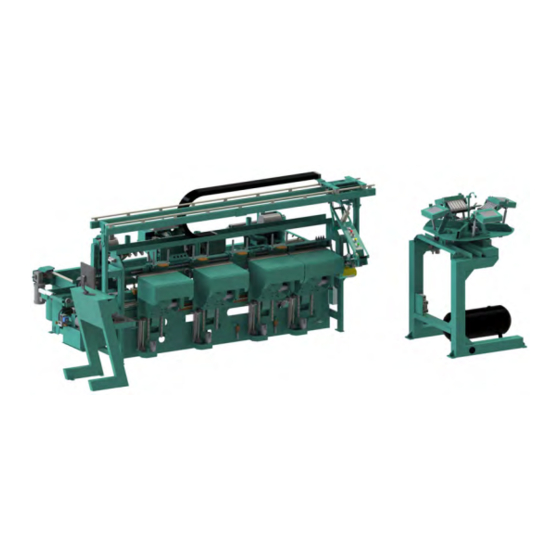
Page 35: 994-X With Rts-Fx Hoppers
Overview of Machine 994-X with RTS-FX Hoppers In-Feed Hydraulic System Six-Shooter Electrical Panel # 1 Valve Bank #1 Hinge Carriages #1-#4 Back Section Lock Plate Assembly Front Section Electrical Panel # 2 Valve Bank Valve Bank #3 Lock Bore Assembly... -
Page 36: About The Rts-Fx Rotary Hopper
90 degree increments. Screws are fed to the 994-X hinge applicator by way of air driven feed-hoses. The quantity of screw-drops will occur based on the quantity of hinges selected for processing at the machine operator’s interface. -
Page 37: Basic Operation Of The Rts-Fx
Screws are sent to the machine. Cylinders (X2): To 994-X Extends drop plate to be flush with Hopper to allow clean drop of screws. Retracts when screws are dropped. Repeats cycle for next Hopper. KVAL 994-X Operation Manual... -
Page 38: Operator Controls
The Operator’s Station can be placed at different locations as per customer requirements. Above are examples of an Operator’s Station attached to the machine and a centrally located station with a Handler interface. Operator’s Stations with touch Screen Interface FIGURE 2-2. KVAL 994-X Operation Manual... -
Page 39: Machine Control
Starts the occur press this sequence of button. machining a door. Disable Auto Feed: LH/ RH Door: Stops Door Feeding Select a Right Through. Hand or Left Hand Door. Machine Controls without Disable Auto Feed FIGURE 2-4. KVAL 994-X Operation Manual... -
Page 40: Door/Jamb Foot Pedal
Door Clamps: Two Clamps per Head. Can be Auto clamped and Manually clamped. Jamb Stop Door Clamps Jamb Ledge Jamb Clamps: Two Clamps per Head. Manually clamped. Jamb Stop Jamb Clamp Jamb Ledge Jamb Clamp Assemblies FIGURE 2-5. KVAL 994-X Operation Manual 2-10... -
Page 41: In-Feed Section
Shooter: Sets and lifts the Door through on jamb away from Eight Shooter out of the hinge the machine. machining process. pocket. Not shown: See “Front Section” on page 2-13. Key Assemblies on the In-Feed Section FIGURE 2-6. KVAL 994-X Operation Manual 2-11... -
Page 42: Door Stops
Spacers are located at the Operator’s Station. To match the length of the jamb, rotate the Jamb stop turrets. The turrets are located at the Out-Feed an In-Feed areas about the Door Stops. KVAL 994-X Operation Manual 2-12... -
Page 43: Front Section
Hinge Carriage # 4 Hinge Carriage # 1 Hinge Carriage # 2 Hinge Carriage # 3 Standard: Pre Drill, Router. Opt CR: adds CR Router. Opt CH: adds Chisels, 4 corners. View of Front Section FIGURE 2-8. KVAL 994-X Operation Manual 2-13... -
Page 44: Hinge Carriage
Changeover from 3-1/2” to 4” hinges is accomplished by selecting the desired size on the touchscreen. The Point to Point Pre-Drill system can be programmed to drill all common hinge patterns automatically. Standard Router Pre-Drill Retract/Extend Cylinders KVAL 994-X Operation Manual 2-14... - Page 45 Pre-Drill: Counter Rotate Router Standard Router Retract/Extend Cylin- ders Hinge Carriage Parts with added Counter Rotate Router (Option CR) FIGURE 2-9. KVAL 994-X Operation Manual 2-15...
- Page 46 Left Chisel Pre-Drill Counter Rotate Router Standard Router Right Chisel Hinge Carriage Parts with added Chisels (Opt CH) and Counter Rotate Router (Opt CR) FIGURE 2-10. KVAL 994-X Operation Manual 2-16...
-
Page 47: About The Six/Eight Shooter System
Screw Delivery Hoses Operator Controls Drive Assembly: • Air Motor • Gearbox • Six Screwdriver Bits Eight bits for Eight Shooter) Magnetic Indexing Fixture. (Hinge Is Placed Here) Photo of Six Shooter on the 994-X FIGURE 2-11. KVAL 994-X Operation Manual 2-17... -
Page 48: Option K: Eight Shooter
Four Door Screw applicators. Indexing Fixture: Magnetic. Aligns screws and attaches the hinge to the door and jamb. The Eight shooter attaches four screws to the jamb and four to the door. Eight Shooter Parts FIGURE 2-12. KVAL 994-X Operation Manual 2-18... -
Page 49: About The Six/Eight Shooter Controls
3-degree bevel front section. simply plunge the head and flip the trap out of position. This will allow the head to retract to the back position. Identify Controls on the Six/Eight Shooter FIGURE 2-13. KVAL 994-X Operation Manual 2-19... -
Page 50: About The Hopper
Any adjustment may cause timing issues with the operation of the Six Shooter. If you think problems are being caused by the cylinders, please contact the KVAL Service Department for direction. Important: Do not put Magnetized Screws in Hopper. Magne- tized screws can cause sluggish response to screws getting stuck. - Page 51 Press the button on the Six Shooter panel which is located mid machine on the Reset front section. Fill the Hopper with new screws. KVAL 994-X Operation Manual 2-21...
-
Page 52: Driver Assembly
Factory set to align hinge. Latch Arm: Latch Arm Cylinder: Latches to the H- Moves latch arm in and out Block to secure in of position. place. Six Shooter and Gear Box Call-Outs FIGURE 2-15. KVAL 994-X Operation Manual 2-22... -
Page 53: Option: Quick Change Knuckle Assembly
Switch to trigger solenoid. To Use this Function: Flip the switch to activate the Solenoid. Place the wide knuckle hinge into the Hinge Appli- cator. See “Quick Start” on page 2-35, for the procedure to apply hinge. KVAL 994-X Operation Manual 2-23... -
Page 54: About The Over-Head Track
Eight Shooter (Opt K): Keeps the Six Shooter in park and allows move- ment down the machine Six Shooter: Keeps the Eight Shooter in park and allows movement down the machine Over-Head Track FIGURE 2-16. KVAL 994-X Operation Manual 2-24... -
Page 55: Back Section
‘X’ axis. on LH Door. Ball Catch Shifts for 6’8'' to 8’0'' Door. Feed Belt: Feeds Door through Machine. Chip Out Location Lock Bore Motor and Drill: Drills locks holes on the face of the door. KVAL 994-X Operation Manual 2-25... -
Page 56: Back View Of Rear Section
Bolt Drill Extend and Retract Cylinder Lock Bore Oil Reservoir Bolt Drill Motor: Machines lock plate on the side of the door. Lock Bore Limit Switches Deep Face Plate Motor and Bit: Routs face plate. Shallow Retracted KVAL 994-X Operation Manual 2-26... -
Page 57: Option Sb: Back View Of Rear Section
Machines lock plate on the side of Ball Screw the door. Right Lock Plate Left Lock Plate Chisel Cylinder: Chisel Cylinder: Squares the edge Squares the edge of the lock plate. of the lock plate. KVAL 994-X Operation Manual 2-27... -
Page 58: Option Bc: Ball Catch Motors
Drills ball catch top edge Ball Catch Motor and Drill: (Out-Feed) on LH Door. Drills ball catch top edge (In- Feed) on RH Door Ball Catch Cylinder: Moves motor assembly to 8’-0'' or 6''-8'' door posi- tion. KVAL 994-X Operation Manual 2-28... -
Page 59: Out-Feed
Air Blow Off (Opt O): next stage. Air Drop Six Shooter: Blows off dust from the Sets and Lifts Six door as it Feeds Out Shooter out of Hinge pocket Key Assemblies on the Out-Feed Section FIGURE 2-17. KVAL 994-X Operation Manual 2-29... -
Page 60: Option O: Air Blow Off
Light is mounted on the Out-Feed end of the 994-X that can be seen by the 700-C Assembly Table Operator. The light will be on when the door in the 994-X is being machined as a right hand door and off for a left hand door. -
Page 61: About The Electrical Panels
If working on the panel, follow the safety protocol as described in Chapter 1. The 994-X system includes a Main Electrical Panel and a High Frequency Panel. Figure 2-18 below, is an overview of the location of assemblies in the panels. -
Page 62: High Frequency Panel
Contactors, Thermal Overload and Control Transformer Lock Bore Motor Bolt-Drill Motor Six Shooter screw Driver In-Feed Ball Catch (Opt BC) Out-Feed Ball Catch (Opt BC) Eight Shooter Screw Driver (Opt K) Overview of the High Frequency Panel FIGURE 2-19. KVAL 994-X Operation Manual 2-32... -
Page 63: Description Of The Six Light Panel
Description of the Six Light Panel Description of the Six Light Panel The six lights on this panel indicate the status of the 994-X system. The sequence that the lights activate is as follows: Control Power Overload Relay E-Stop Stop... -
Page 64: About Sensors
The Limit Switch is activated by an assembly moving a switch arm. • Depending on the model of limit switch, the amount of pre-travel (amount of movement from the arms resting position) is either 5 or 20 degrees before the limit switch actuates (Clicks). Switch Arm KVAL 994-X Operation Manual 2-34... -
Page 65: Quick Start
Quick Start Quick Start Ensure factory air is present at the machine and the 994-X main air supply valve is turned on. Power up the 994-X. See “How to Power Up the 994-X” on page 2-37. Home the 994-X. See “Home the 994-X” on page 2-38. - Page 66 Six Shooter or pressing the Unclamp Jamb Clamp foot pedal. To continue, repeat from the load door section in this quick start. If completed, shut down the machine. See “How to Power Down the 994-X” on page 2-38. KVAL 994-X Operation Manual 2-36...
-
Page 67: Powering Operations For The 994-X
Powering Operations for the 994-X Powering Operations for the 994-X This section describes how to power up and power down the 994-X. Powering up the system includes: • Applying power to the entire system. • Starting the Control Circuit. Powering down the system includes: •... -
Page 68: Home The 994-X
The 994-X must go through a homing routine before any operations are performed. The homing routine sets a zero reference from which the 994-X measures its movement and cutting process. If power is lost or the 994-X is reset, the homing routine must be performed again to reset the zero reference. -
Page 69: Emergency Shutdown And Recovery
Powering Operations for the 994-X Emergency Shutdown and Recovery There are several emergency shutdown (E-Stop) switches located at key points around the machine. Note: Depending on the machine option, E-Stop buttons may be located at various locations. The E-Stop switches are to be used when the machine is out of control or is about to damage personnel or equipment. -
Page 70: Description Of User Interface Screens
Note: Use this information to isolate issues if having problems with the machine. Controlling Access to User Screens The 994-X has the ability to lock out changes to certain parameters such as presets and calibra- tions. Note: Locked out parameters may vary due to customer design criteria. -
Page 71: Menu Maps Of The Operator Screens
Width Adjust Jog Hinge Carriage #1 Door Stop / Clamp[ Jog Hinge Carriage #2 Skip Hinges Jog Hinge Carriage #3 Feed Control Jog Hinge Carriage #3 Burn Chipout Test Mode Exit Application Jog Lock Location KVAL 994-X Operation Manual 2-41... - Page 72 Lower Right Chisel Pre-Drill Feed Sys timing Hinge Carriage Jamb Shelf Height Plate Fast Timers Plate Slow Timers See “About the Diagnostic Screen” on Diagnostics page 2-58. 990-H Log screen Total Door Count Daily Door Count KVAL 994-X Operation Manual 2-42...
-
Page 73: About The Main Screen
About the Main Screen About the Main Screen The Main Screen is also the startup screen for the 994-X. All the basic user interface controls are available to process a door are available on this screen. Options and customer preferences can change the interface buttons. For samples of... - Page 74 This button stops the door in the process. Shut Down System Button This button shuts down the computer. Use this button as part of the shutdown pro- cess.See “How to Power Down the 994-X” on page 2-38 Preset Selection Button Group Pressing a preset button calls one of twelve presets that are stored in memory.
- Page 75 Pre-Drill tion. To set Pre-Drill parameters, see “About the Pre-Drill Screen” on page 2-51. This section also contains the file list window, which displays files that are available to use. KVAL 994-X Operation Manual 2-45...
- Page 76 Enable or disable the Automatic Screw Drop. Press the to deliver a burst of Manual Air Injection air to the drop location to free any stuck screws or push a screw through. KVAL 994-X Operation Manual 2-46...
-
Page 77: About The Setup Screens
About the Setup Screens Note: This section describes the menus in the Setup Screens. For information about performing calibration, ”. See “Chapter 3, Calibration of the 994-X Select the Button on the Main Screen to open access to the: Setup •... - Page 78 Vertical: The amount of time, in seconds, to give the vertical movement of the lock plate when in ‘Fast Plate’ mode. Horizontal: The amount of time, in seconds, to give the horizontal movement of the lock plate when in ‘Fast Plate’ mode. KVAL 994-X Operation Manual 2-48...
-
Page 79: About The Setup Hinges 1-4 Screens
Figure 2-1 on page 4 head locations. • Setup Hinge 1 • Setup Hinge 2 • Setup Hinge 3 • Setup Hinge 4 Chisels: Option CH only Counter Rotate Route Hinge Setup Menu (1 of 3) FIGURE 2-22. KVAL 994-X Operation Manual 2-49... - Page 80 Use this menu to compensate for minor changes in tooling during calibration. Option CR: Chisel Adjustments These adjustments move Chisels in the X, Y, and Z direction. Use this menu to compensate for minor changes in tooling during calibration. KVAL 994-X Operation Manual 2-50...
-
Page 81: About The Pre-Drill Screen
The number '0' entered in both X and Y are equal to no drill. Important: Never enter a negative number in the 'Y' parameter. The pre-drill will try to drill off the door into the delrin. See the figure on the next page. KVAL 994-X Operation Manual 2-51... - Page 82 About the Setup Screens Sample of 4'' Hinge Dimensions 'X' Zero Point 'Y' Zero Point Sample of 3.5'' Hinge Dimensions 'X' Zero Point 'Y' Zero Point Pre-Drill Samples FIGURE 2-24. KVAL 994-X Operation Manual 2-52...
-
Page 83: About The Hopper Screen (Rotary)
Hopper for identification pur- poses. Hints: • A positive number moves the Hopper in the Clockwise direction. • For more information about using the calibration boxes, See “Enter a Positive or Negative Num- ber?” on page 3-7. KVAL 994-X Operation Manual 2-53... -
Page 84: About The Manual Operation Screens
At this screen, you can control certain functions of the machine in manual mode. This screen is mainly used in troubleshooting, checking cut specifications, and maintenance. Manual Operation Screen FIGURE 2-25. Jog Carriage screen FIGURE 2-26. KVAL 994-X Operation Manual 2-54... - Page 85 Toggle Buttons: The buttons to the right toggle auto functions on or off. For descriptions of these but- tons, see “Auto Enable and Disable Buttons and Screw Hopper” on page 2-46. KVAL 994-X Operation Manual 2-55...
- Page 86 If a narrow door gets stuck in a machine, push this button to lift and unclamp. Door can then be moved manually out of the machine. Jog Lock Location Use this menu to move the lock location on the back sec- tion. KVAL 994-X Operation Manual 2-56...
- Page 87 To stop, release the button. Select the white box and enter the speed of the Speed: carriage. The range is 1% to 100%. Use the number pad to enter the desired speed and press OK when fin- ished. KVAL 994-X Operation Manual 2-57...
-
Page 88: About The Diagnostic Screen
About the Diagnostic Screen About the Diagnostic Screen The Diagnostic Screen displays all the tasks the 994-X performs. This screen can help with trou- bleshooting by associating an error code to machine sections or functions. The top line will have the most current routine that is running. -
Page 89: Option Sb: About The Cnc Back Section Operator Screens
CNC Back Section option. Main Screen Square Plate: Some SB options have a Toggle to turn the square plate cut- ting routine ON or OFF. Lock Plate: Adjust Lock Plate to the X, Y and Z specifica- tions. KVAL 994-X Operation Manual 2-59... -
Page 90: Option Sb: Lock Calibration Screen
Option SB: Lock Calibration Screen Note: This section describes the menus in the Setup Screens. For information about performing calibration, ”. See “Chapter 2, Calibration of the 994-X The following screen is added in the CNC Back Section option. Chisels: Calibrates... -
Page 91: Option Sb: Manual Screen
Lock Access Button Access Tools (OFF): will move to a position for easy access. Lock Plate with Lock Access Button Access Tools (ON): Moves the out further if more room is needed to access tooling. Lock Plate KVAL 994-X Operation Manual 2-61... -
Page 92: Option: Ar-Hq2
Option: AR-HQ2 Some machines include the Rotate Table AR-HQ2. In this case, AR-HQ2 controls and menu but- ton are located on the Main Screen. Note: For information on 994-X with an AR-HQ option, see the “AR-HQ2 Control the direction Operation and Service Manual”. -
Page 93: Option: Checking Screw Delivery
After screws are cleared, continue with process. Screw Delivery Sensors: Ferro sensors located on each tube. Fail Indicator Light: If a screw is not delivered to the index of the six shooter this light will turn on. KVAL 994-X Operation Manual 2-63... -
Page 94: Option Nd: Auto Narrow Door
Note: Lock functions are not available in the narrow door setting. Pneumatic Controls for Narrow Door Narrow Door Fence Narrow Door Sensors: The width of the door is com- pared to the Standard Sen- sor inputs to activate. Standard Door Sensors KVAL 994-X Operation Manual 2-64... -
Page 95: Option N: Weather Strip Brackets
Option N: Weather Strip Brackets A protective bar across top of H block keeps the strip up and away from the routers. Protective Bar: Keeps Jamb weather stripping from inter- fering with the machining pro- cess. H Block Carriage KVAL 994-X Operation Manual 2-65... -
Page 96: Option: Securing Split Jambs
During process, press the button. Fire Side Nailer Note: The nail gun will not fire unless the enable button is activated on the Operators Screen and the safety switches are activated by the male split jamb. KVAL 994-X Operation Manual 2-66... - Page 97 Notes:...
- Page 98 Calibration of 994-X CHAPTER 3 This chapter describes the steps to calibrate the 994-X, Door Pre-Hanging Machine. Chapter 3 at a Glance Section Name Summary Page The Benefits of calibration and when to calibrate. page 3-2 About Calibration Specifications of the Calibration Routine.
-
Page 99: About Calibration
The KVAL 994-X has a built in Calibration routine to cut a horizontal slot with known parame- ters. The routine allows you to make the cut, measure, observe any anomalies, and help isolate to the component that causes the problem. -
Page 100: Flow Chart Of Calibration
About Calibration Flow Chart of Calibration The flow chart below illustrates the steps in performing a calibration on the 994-X. Calibration Process Flowchart FIGURE 3-1. KVAL 994-X Operation Manual... -
Page 101: About The Kval Calibration Routine
About the KVAL Calibration Routine About the KVAL Calibration Routine The calibration routine creates a reference cut to check settings against a “known good” source. The routine is used to verify the front section. It routes a horizontal slot and drills a center hole at precise specifications. -
Page 102: Calibration Slot Drilling Specifications
About the KVAL Calibration Routine Calibration Slot Drilling Specifications The calibration routine will route a slot with known dimensions as a reference. The placement of the slot and the parameters of the cut can help in dialing in the calibration. Each tool in the Car- riage Head will be part of the slot drilling process. -
Page 103: Run The Calibration Routine
Disables Hinge 2 of the hinges leaving one hinge enabled. Load the Door and Start the Cut Load the test door into the in-feed of the 994-X. Verify the setup and check for machine is safe to run. Press the button, to begin the process. -
Page 104: Check Specifications Of The Front Section
‘Z” axis, the thumb represents the positive direction of the ‘Y” axis, then second finger represents the positive the direction of the ‘X’ axis. Either Front Section or Back Section Cuts Y Axis Positive movement Z Axis Positive movement X Axis Positive movement KVAL 994-X Operation Manual... -
Page 105: General Instructions To Adjust Parameters
Offset: Select this button to add or to set a reference and end subtract the measured number of adjustment to store it. entered. Base: Keeps a Running Total of measured numbers entered. Sample of an Adjustment Menu FIGURE 3-5. KVAL 994-X Operation Manual... -
Page 106: Step 1: Hinge Carriage Calibration
Check Specifications of the Front Section Note: KVAL suggests to follow the steps in the order below. Step 1 Verify and Adjust the Hinge Carriage Step 2 Verify and Adjust the Router and Counter Rotate Router Calibration Step 3 Verify and Adjust the Pre-Drill Calibration Step 4 Verify and Adjust the Chisels Calibration (Opt. - Page 107 Enter the offset in this box. Select the check mark to confirm this number and exit to go back to the Setup screen. Exit out of the Setup screen and rerun the Calibration test. Re-measure the parameters of slot. KVAL 994-X Operation Manual 3-10...
- Page 108 If the depth is too deep, enter a negative number of the difference of the measured and the desired depth. If the depth is too shallow, enter a positive number of the difference of the measured and the desired depth. Rerun tests until the correct depth is achieved. KVAL 994-X Operation Manual 3-11...
-
Page 109: Step 2: Router Calibrations
X,Y and Z parameters. Router Calibration Menu FIGURE 3-8. Repeat until cut is centered. Select the button to finish. Combine with Base Repeat until cut is centered. Click “Combine with Base” to finish. KVAL 994-X Operation Manual 3-12... -
Page 110: Step 3: Pre-Drill Calibration
Run the Calibration Routine. See “Run the Calibration Routine” on page 3-6. Check, measure, and calculate specifications of Pre-Drill cut. To set a new reference, go to the calibration menu and select Combine with Base Enter calculations. KVAL 994-X Operation Manual 3-13... - Page 111 Z: To increase the depth, enter a positive value. To decrease the depth, enter a negative value. Pre-Drill Router Calibration Menu FIGURE 3-9. Repeat until hole is centered. Select to finish. Combine with Base KVAL 994-X Operation Manual 3-14...
-
Page 112: Step 4: (Option Ch) Chisel Calibration
Upper Left Chisel Chisel Jamb Door Lower Left Lower Right Chisel Chisel Adjusting the Chisels Identify the corner or comers to be calibrated. a.Upper Left Chisel b.Upper Right Chisel c.Lower Left Chisel d.Lower Right Chisel. KVAL 994-X Operation Manual 3-15... - Page 113 Click the “Combine with Base” button to combine the two numbers to create refer- ence. KVAL 994-X Operation Manual 3-16...
-
Page 114: Calibration Of The Back Section
Calibration of the Back Section Calibration of the Back Section For the 994-X, there are two screens available to calibrate the back section. To calibrate, follow the directions in “Enter a Positive or Negative Number?” on page 3-7 From the select -->... - Page 115 Note: Before adjusting the Slow Lock Plate Timing, make sure the Fast Plate Routine is set properly adjusted. If the settings are in adjust the Extend Time, Slow Lock Plate Timing. Fast and Slow Lock Plate Timing Menu FIGURE 3-12. Vertical: KVAL 994-X Operation Manual 3-18...
- Page 116 Enter a positive or negative number to move the tool in the desired direction. Moves Tool Set Z: Positive number Positive moves tools in, negative Number number moves tools out Positive Negative Negative Number Number Number KVAL 994-X Operation Manual 3-19...
- Page 117 Note the Positive # Negative # measurement value. Chisel Calibration (Back Section) These adjustments move Chisels in the X, Y, and Z direction. Use this to compensate for minor changes in tooling during calibration. KVAL 994-X Operation Manual 3-20...
- Page 118 Enter a positive or negative number to move the tool in the desired direction. Upper Upper Left Right Lower Lower Right Left Positive Positive number Number moves tools in, nega- tive number moves Negative Negative Positive tools Number Number Number KVAL 994-X Operation Manual 3-21...
- Page 119 Calibration of the Back Section KVAL 994-X Operation Manual 3-22...
- Page 120 2-38 combine with base how to use in-feed section control power indicator light description 2-33 key assemblies control transformer switch input and output terminals power up 2-37, 2-38 location electrical panels 2-32 KVAL 994-X Operation Manual...
- Page 121 Guidelines 1-14 reset machine button lockout procedure 1-12 description user interface 2-44 return material authorization (RMA) 1-16 returning the product to Kval 1-16 machine calibration group right hand door description 2-48 selecting 2-35 machine feed back router...
- Page 122 2-40, 2-41 location in high frequency panel 2-32 width adjust user interface description 2-55 X-axis calibration routine illustration of adjustment 3-10 Y-axis calibration hinges 3-10 illustration of calibration 3-11 zero-energy start-up clean up 1-14 inspect 1-14 KVAL 994-X Operation Manual...
- Page 123 KVAL 994-X Operation Manual...
- Page 125 Contacting KVAL Customer Service Phone and Fax: Mailing address: In the U.S and Canada, call (800) 553-5825 or fax Customer Support Department (707) 762-0485 Kval Incorporated Outside the U.S. and Canada, call (707) 762-7367 825 Petaluma Boulevard South or fax (707) 762-0485 Petaluma, CA 94952 Email: service@kvalinc.com...
Need help?
Do you have a question about the 994-X and is the answer not in the manual?
Questions and answers