Kval 990-FX Operation Manual
Pre-hanging door system
Hide thumbs
Also See for 990-FX:
- Operation and service manual (172 pages) ,
- Service manual (120 pages) ,
- Operation manual (96 pages)

Related Manuals for Kval 990-FX


Summary of Contents for Kval 990-FX
- Page 1 Operation Manual Published: June 7, 2023 Innovation, Quality & Honesty 990-FX Pre-Hanging Door System Includes Machines with Array Hoppers and Machines with RTS Hoppers...
- Page 2 Mon-Thu:6:00 AM - 4:00 PM PST Fri: 6:00 AM - 3:30 PM PST Parts Contact us for all parts related needs, from orders to inquiries. Call, email, contact us on our web- site at the “Contact Us” page. email: parts@kvalinc.com KVAL 990-FX Operation Manual...
- Page 3 KVAL 990-FX Operation Manual Technical Support For machinery support and troubleshooting. Call, email, contact us on our website at the “Contact Us” page. Mon-Fri:4:00 AM - 4:00 PM PST email: support@kvalinc.com Field Service Support For any other inquiries or to schedule on-site service. Call, email, contact us on our website at the “Contact Us”...
- Page 4 Revisions June 7 2023: Page 2-5 to Page 2-6 Added mechanical back section three degree setup instructions. KVAL 990-FX Operation Manual...
-
Page 5: Table Of Contents
Table of Contents Introduction to the 990-FX Chapter 1 Overview of the 990-FX Door Hanging System....... 1-1 Metal Door and Jamb Machine.............1-1 Table of Available Options ..............1-2 About this Manual .................1-4 Safety First!................1-5 Safety Sheet Sign-Off Sheet..............1-5 Safety Terminology of Labels..............1-5 Safety Guidelines.............. - Page 6 Safety Sign-Off Sheet .............. 1-17 A Note to the Operator................1-17 Operation of the 990-FX Chapter 2 Initial Powering Operations for the 990-FX Line ...... 2-1 How to Power Up the Line ..............2-1 Home the 990-FX .................2-2 How to Power Down the Machine............2-3 Emergency Shutdown and Recovery ...........2-3...
- Page 7 If the Beam is Broken .................4-10 To Resume Normal Operation after an Beam is Broken.....4-11 About Gates Latches ................4-12 Air Brake on 990-FX Screw Shooter...........4-12 About the In-Feed Section ............4-14 About the Front Section ............4-15 Carriage Head Shifting Process ............4-16...
- Page 8 Network Diagram ................4-31 Backing up the Computer ..............4-31 Procedure for Backing up Data............4-31 About Remote Connection to KVAL Service........4-32 Option BC: Ball Catch.............. 4-33 Option N: Dust Blow off System ..........4-34 Option 8.0: Machine Accepts 8.0 Foot Doors ......4-35 Option 8.0: About the Shift Function ...........4-35...
- Page 9 Introduction to the 990-FX CHAPTER 1 This chapter provides an overview of the Door Hanging System and important safety Kval 990-FX information to follow when operating the machine. TABLE 1- 1. Section Name Summary Page This section provides an overview of the...
-
Page 10: Overview Of The 990-Fx Door Hanging System
Overview of the 990-FX Door Hanging System Overview of the 990-FX Door Hanging System is the fastest and most productive pre-hanging system available in the industry. Kval's 990-FX will rout a door and jamb for three or four hinges, drill pilot holes for the hinge 990-FX screws, mortise for the lock, and apply three or (Opt four) hinges. -
Page 11: Table Of Available Options
Light will be mounted on the out-feed end of the 990- FX that can be seen by the 700-C Assembly Table operator. The light will be on when the door in the 990-FX is being machined as a right hand door and off for a left hand door. Option N... - Page 12 Overview of the 990-FX Door Hanging System Option Title Description Option Z Screw Changing Hoppers Screw-changing hoppers for changing screw colors. Price includes three 6-slot screw hoppers. Option Tooling and Lubricant Package Please review with your Kval consultant to determine your needs.
-
Page 13: About This Manual
Overview of the 990-FX Door Hanging System About this Manual This manual is part of a package delivered with the machine line. Integration Package includes the following manuals: Operation Manual Chapter Title Description Introduction Descriptions of Machine Line and Safety Information. -
Page 14: Safety First
Safety Terminology of Labels In addition to the nameplate, machines may have other warning labels or decals that provide Kval safety information to operators. Safety labels should be clearly visible to the operator and must be replaced if missing, damaged, or illegible. -
Page 15: Safety Guidelines
Safety Guidelines Safety Guidelines In addition to the caution and warning labels affixed to this machine, follow the guidelines below to help ensure the safety of equipment and personnel. Different versions of the stickers may have been applied to the machine. The Note: intent of safety is the same. -
Page 16: Lockout/Tagout Guidelines
Lockout/Tagout Guidelines Lockout/Tagout Guidelines Follow these Lockout/Tagout guidelines, • Place a tag on all padlocks. On the tag, each operator must put their own name and date. (These locks are only to be removed by the person who signs the tag) •... -
Page 17: Lockout/Tagout Procedure
Lockout/Tagout Procedure Lockout/Tagout Procedure This policy is required by OSHA regulation 1910.147 and Cal OSHA’S SB198 ruling of July 1991. Use the following lockout procedure to secure this machine while it is powered down. During a lockout, you disconnect all power and shut off the air supply. -
Page 18: Lockout/Tagout Air Supply
Lockout/Tagout Procedure push the red tab to pop it out. Place a pad- Disconnect style Electrical Panels: lock through the hole. Place your tag on the padlock, as per the tagout guide- lines below. (see illustration below). Turn Switch to the Lock and Tag out Insert Lock into hole. - Page 19 Lockout/Tagout Procedure Before removing the locks and tags, the person who attached them shall inspect the equipment to ensure that the machine will not be put in an unsafe condition when re-energized. The lock and tag can now be removed (only by the person(s) who placed them), and the machine can be re-energized.
-
Page 20: Zero-Energy To Start-Up
Replace Guards Replace all equipment guards. If part of equipment cannot be properly adjusted after start-up with guard on, contact the See “Getting Help from Kval” on page 1-16. Kval Technical Support. Check Controls Confirm that all switches are in the “OFF” position. Please be advised that some components of the machine may start automatically when energy is restored. -
Page 21: Close The Cage Gate
Zero-Energy to Start-Up Close the Cage Gate Verify all cage gates are securely closed. Ensure all safety protocols are in effect. Zero-Energy to Start-Up 1-12... - Page 22 Getting Help from Kval Getting Help from Kval Before you seek help, first try the troubleshooting procedures. Follow the procedures below. If you are unable to resolve the problem: Locate the machine’s Specification Plate and record the serial number, 3 phase volts, electrical print number, and air print number.
-
Page 23: Kval Return And Warranty Policy
Kval Return and Warranty Policy Kval Return and Warranty Policy goal is to provide customers with high quality products. If, for any reason, you are not com- Kval's pletely satisfied with your purchase, please contact us at: Email: parts@kvalinc.com +1 (800) 553-5825 Phone: •... -
Page 24: Customer Errors
Kval Return and Warranty Policy Customer Errors If the item is to be returned due to customer ordering error, the customer must return the item to or the shipper of origin at its expense. A 15% restocking fee may apply to manufactured... - Page 25 Kval Return and Warranty Policy Page Intentionally Left Blank Kval Return and Warranty Policy 1-15...
-
Page 26: Safety Sign-Off Sheet
It is recommended you make a copy of this sheet for new operators. If a copy is Note: needed, you may download a PDF at the website (http:// Kval www.kvalinc.com). You may also contact our at (800) 553- Technical Support 5825 or email at support@kvalinc.com. - Page 27 Operation of the 990-FX CHAPTER 2 This chapter describes the power-up and user interface of the Kval 990-FX Door Hanging System. The content is geared to help operators understand the basic operation of the 990-FX. Chapter 2 at a Glance...
-
Page 28: Initial Powering Operations For The 990-Fx Line
Initial Powering Operations for the 990-FX Line Initial Powering Operations for the 990-FX Line This section describes how to power up and to power down the Line. 990-FX Powering up the system includes: • Applying power to the entire system. -
Page 29: Home The 990-Fx
Initial Powering Operations for the 990-FX Line Push the button to act as a Reset. Hinge Loaded This process is a safety precaution to ensure the no personnel is in the machine Note: staging area. Hinge Loaded Button All the lights turn to green. -
Page 30: How To Power Down The Machine
Initial Powering Operations for the 990-FX Line How to Power Down the Machine Push the button for each machine, located on the Stop Operator’s Station. Shut down the operating system, by selecting Shutdown from the Desktop. Make sure Windows is shutdown completely before Note: turning off the machine. -
Page 31: Mechanical Setup For Back Section 3 Degree Bevel
If for some reason the faceplate is not cen- tered on the latch hole, you can adjust the screws that contact the turret bolts. If both the plate and latch hole are off-center, contact Kval Service Support for instructions on shimming the self-cen- tering clamp system. -
Page 32: Adjust Plate Router To Zero-Degree Bevel
Mechanical Setup for Back Section 3 Degree Bevel Depending on the square edge measurement, turn the router depth adjustment turret to align the sliver or white bolt. For bolt selection, see Table 2- 1 on page 2-4. Slide the router back into position and tighten the bolts to secure. To tighten the bolts on the 0-to3-degree adjuster, loosen the kip handle (turn to left), then pull up on the black knob above the kip handle. -
Page 33: Machine Start Summary
Machine Start Summary Machine Start Summary This is a summary of the start sequence for the Line. 990-FX Set-Up If setting up for a 3 degree bevel on the back section, mechanical adjustments on Note: the back section need to be completed. See “Mechanical Setup for Back Section... -
Page 34: Load Jamb And Clamp Jamb
Machine Start Summary After the machines have the sequence performed and door is fed in and auto- Home clamped, perform these steps. Select the desired . Verify that the information is correct. Preset For Example: Check Check Door Width, Auto Feed enabled, is enabled, and Auto Width... -
Page 35: Load Hinges And Process The Door
Machine Start Summary Load Hinges and Process the Door After clamping the jamb, press the Start button. Sequence Attach a hinge to each Shooter Hinge Applica- Attach Hinges with the hinge pin towards the top of the door. Exit Area Beyond the Light Curtain Exit the area beyond the Light Curtain. -
Page 36: Description Of User Interface Screens
Calibrate the assemblies on the machine. messages can be seen here for troubleshooting. Refer to Chapter 3 of this manual. See “Diagnostic Screen” on page 2-22. See “About the Setup Screen” on page 3-4. 990-FX Menu Map FIGURE 2-1. Description of User Interface Screens... -
Page 37: Machine Feed Back
Description of User Interface Screens Machine Feed Back At the top and at the bottom right hand corner of all user screens is status feedback information. The information generated is as follows:’ 1. General Machine Status 2. Front Section Status 3. -
Page 38: About The Main Screen
The Main Screen is the startup screen for the . At this screen, all the basic user interface 990-FX controls are available to run a door. For descriptions refer to the matching letter icon. letter icon. Note: Screen layouts may differ due to options and customer requests. The operation is the same except button placements may differ. -
Page 39: Main Screen: Carriage Head With Rts
About the Main Screen Main Screen: Carriage Head with RTS The controls are the same as a machine with an Array Hopper or integrated Hoppers with the exception of three Hopper buttons to represent each Hopper set on the About the Main Screen 2-12... -
Page 40: Machine Controls
Shut Down Button This button shuts down the computer. Use this button as part of the shutdown pro- cess.See “Initial Powering Operations for the 990-FX Line” on page 2-1 Exit Application Button This button shuts down the operator interface screen and defaults to the Windows Desk-... - Page 41 About the Main Screen Auto Modes These buttons toggle auto functions : Press to toggle the auto feed Auto Feed Auto Feed . In , the feed system will bring in and clamp Auto mode a door, wait for processing to complete, then feed the door to out.
- Page 42 About the Main Screen Preset Selection Button Group Pressing a preset button, calls one of twelve pre- sets stored in memory. Pressing the button allows the operator to store the active Modify Preset Main Screen parameters. After pressing the button: Modify Preset Select one of the gray buttons in which to save the parameters.
-
Page 43: Lock Group
About the Main Screen Hinge Modes (Screws) These buttons toggle auto functions of the screw func- tions of the Hoppers. Screw Controls • Press to Enable or Disable all Screw pickup. Screws: • Press to Enable or Disable Screw pickup Screw 1-3: for individual Hoppers. - Page 44 About the Main Screen settings include: Lock Group • Press the Lock button to enable or disable the lock section machining process. If Lock: disabled, the back section will not machine the door • Set the lock position. Lock (#1-3): •...
-
Page 45: About Manual Operation
About Manual Operation About Manual Operation At this screen, control certain functions of the machine in manual mode. This screen is mainly used in troubleshooting, checking cut specifications, and maintenance. Screen layouts may differ due to options that were ordered with the machine. Note: Manual Operation Screen FIGURE 2-4. -
Page 46: Width Adjust
About Manual Operation Width Adjust • : Press and hold the button to open the width adjust car- Open Open riage. To stop the carriage, release the button. The carriage will also stop if the positive travel limit eye is Note: activated. -
Page 47: Lock Manual Control
About Manual Operation Lock Manual Control See the Service Manual for the process to 990-FX change Chipout Blocks. Lock Location: • Press and hold buttons to jog the Left or Right: lock location left or right. To stop, release the but- ton. - Page 48 About Manual Operation Screw Delivery Manual Control • Press (Option) Quick Dump Hopper: button to dump the screws in an active Hoppers. • Press to clear screws in Hopper system. Clear: • Press this button to start the loading process Load: of the Hoppers •...
-
Page 49: Diagnostic Screen
The Diagnostic screen displays all the tasks the performs. This screen can help with trou- 990-FX ble shooting by associating the error code to machine sections or functions. The top line will have the most current routine that is running. If the machine issue can not be resolved, call Inc. - Page 50 Diagnostic Screen Door Count box keeps track of all doors processed on the machine and the daily Door Count count of doors processed. The door count cannot be reset. The count can be Total Daily reset. Use the daily count to keep track of the throughput of daily manufacturing. Reset Count: Push to reset the Total: Number of doors pro- Daily count of doors.
-
Page 51: About The Light Tower
About the Light Tower About the Light Tower indicates the working status of the system. Highly visible indicator lights are Light Tower mounted on top of the Electrical Boxes. A series of colors and flashing codes helps determine the machine error. In this section, troubleshooting steps are defined. -
Page 53: About Calibration
About the Setup Screen of the 990-FX CHAPTER 3 At he screen, calibration of assemblies are performed. Setup Chapter 2 at a Glance Section Name Summary Page Description of fundamentals of calibration. page 3-1 About Calibration Description of the Setup Screen. -
Page 54: Before You Calibrate
Calibration routine to cut a horizontal slot with known parameters. Kval 990-FX The routine allows you to make the cut, measure, observe any anomalies, and help isolate to the component that causes the problem. -
Page 55: Flow Chart Of Calibration
About Calibration Flow Chart of Calibration The flow chart below illustrates the steps in performing a calibration on the 990-FX Calibration Process Flowchart FIGURE 3- 1. About Calibration... -
Page 56: Enter A Positive Or Negative Number
Maximum offset is 0.50 inches. If more than 0.50 inches of adjustment is Note: needed, there is a high probability that another issue may be causing a problem. If issues can not be resolved, contact the Kval Service Center (1-800- Kval Inc. -
Page 57: About The Setup Screen
About the Setup Screen About the Setup Screen Select the Button to perform a calibration of the lock location. This calibration adjusts the Setup position of the lock carriage in the X,Y,and Z direction. Use this screen if the parameters of the rear machining is not in specification. -
Page 58: Calibration Steps For The Lock Location
About the Setup Screen Calibration Steps for the Lock Location uses the X axis to tune the lock location. See “Enter a Positive or Lock Location Calibration Negative Number” on page 3-3 for information about entering data. Below is a illustration on face plate movement. -
Page 59: Adjusting Lock Location
About the Setup Screen Adjusting Lock Location Select the size door (6'8''-7'0''-8'0'') Select Right Hand or Left Hand depending on the door run through process. Under Base, select the button. Combine with Base Enter a positive number to move the lock cut to the left. Enter a negative number to move the lock cut to the right. -
Page 60: Calibration Of Screw Shift
About the Setup Screen • This is distance when the clamped door is Infeed Stop: located after the “After-Indeed eye.” • This is the distance the when clamped Out feed Stop: door is located after the “Before-Out-feed eye.” Calibration of Screw Shift 4 Head Machine Adjust the Screw Shift locations for: Heads 1,2 are paired and Heads 3,4 are paired. -
Page 61: Calibration Of Rts Hoppers
Calibration of RTS Hoppers Calibration of RTS Hoppers On this screen, the Hoppers can be identified with suitable names. The labels are displayed on the Main Screen. The rotary Hopper stand ( ) can also be adjusted. Hopper Names: All Hoppers: Enter a descriptive name to identify the Hopper. - Page 63 Tour of the 990-FX CHAPTER 4 This chapter describes components, assemblies, of the Kval 990-FX Door Hanging System. content is geared to help operators understand the basic operation of the 990-FX. Chapter 4 at a Glance Section Name Summary Page Table of Common Terms.
-
Page 64: Machine Component Terms
Machine Component Terms Machine Component Terms This table includes definitions of common terms. Terminology Electrical Electrical Panels contain the brains and power for the machine. The Main Electrical Panel contains the main PLC and servo drives. The High Fre- Panels quency Panels contain the VFD’s to drive routers, width adjust, and feed motors. -
Page 65: Common 990-Fx Line Layout
• The door is placed onto the powered roller • )The door is fed into the 990-FX automatically or with a call door function. • After the door is fed into the 990-FX the action is repeated • For a detailed description of the Feeder, see... -
Page 66: Assembly Identification On Machine
Common 990-FX Line Layout Assembly Identification on Machine The illustrations in this section show the machine layout of a machine with an Array Hopper and a machine with a RTS Hopper Machine with an Array Hopper The illustration blow depicts a machine with 4 Carriage Heads. -
Page 67: Machine With Rts
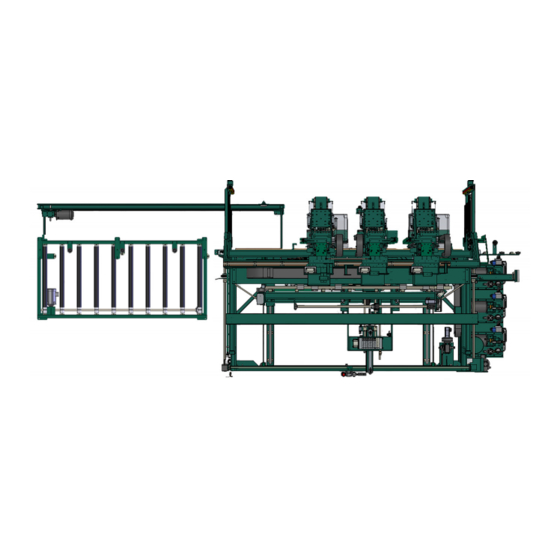
Common 990-FX Line Layout Machine with RTS The illustration below depicts machine with 3 Carriage Heads. Operator’s Station In-Feed Air Tank Light Curtain Carriage Head #1 Screw Shooter #1 Carriage Head #2 Lock Bore Screw Shooter #2 Assembly Carriage Head #3... -
Page 68: About The Rts
About the RTS About the RTS The RTS Hopper sets are designated by Letters A, B, and C. Different screw colors can be loaded into each hopper set. Each set of Hoppers can be activated through the user interface screen. After activated, the Hoppers rotate to the loading position. -
Page 69: Summary Of The Controls On The Machine Line
Operator Station 990-FX controls. Touch Screen Interface: Main Control of the 990-FX. Auto load and run predetermined parameters on doors. Manually control the door path and process through the line. Machine diagnostics are included, as well as inter- net support and connectivity for remote support via our Service Support. -
Page 70: Descriptions Of Machine Controls
Summary of the Controls on the Machine Line Descriptions of Machine Controls On the each machine has a switch and a button. Main Control Panel, Control Circuit Start Stop For detailed information about the start-up process, see “Machine Start Summary” on page 2-5. Lock: Control Power: Lock out access to... -
Page 71: Foot Pedal
The Screw-Shooter heads will also begin to move into position. Door Auto RH / LH: Press for Auto Run, or to receive either a left-hand or right-hand incoming door. When in “Auto Door” mode, the 990-FX receives information about the incoming door from the incoming machine. -
Page 72: Hinges Loaded Button (Light Curtain Status Light)
Summary of the Controls on the Machine Line Hinges Loaded Button (Light Curtain Status Light) The Hinge Loaded button is located on the frame. Light Curtain Hinges Loaded: Step out of the Safety Light Curtain a Press this button after the hinges are loaded on to Hinge Applicators. -
Page 73: Safety Controls
Safety Controls Safety Controls Emergency Shutdown and Recovery Emergency shutdown ( ) switches located at key points around the E-Stop machine. Operate the switches when the machine is out of control or is about to E-Stop injure personnel or damage equipment. When an switch is activated, high voltage power is cut to the E-Stop... -
Page 74: To Resume Normal Operation After An Beam Is Broken
Safety Controls Emitter Receiver Status Indicator and Hinges Loaded (Reset) Machine in operation Breaking beam stops the machine Operation of Safety Curtain FIGURE 4- 3. To Resume Normal Operation after an Beam is Broken If a beam is broken, use the following procedure to recover. Push the button on START MACHINE... -
Page 75: About Gates Latches
Safety Sensor Door Latch Gate Latches FIGURE 4- 4. Air Brake on 990-FX Screw Shooter Air brakes are attached to the assemblies. The brakes will lock the six shooter in Screw Shooter place avoiding a crash to the head. The brakes are controlled by a lack of air pressure and will lock when the air pressure drops below a reference level. - Page 76 Safety Controls Bypass valve will bypass air causing the brakes to lock Brakes are located on each side of the Screw shooter assemblies Air Brake System FIGURE 4- 5. Safety Controls 4-13...
-
Page 77: About The In-Feed Section
Six Shooter from Hopper In-Feed System: Lock Back Section: Door is delivered from previous machine and fed Faceplate routing into 990-FX for process- and boring for lock ing. and bolt In Pocket Sensor: A through beam that Frame... -
Page 78: About The Front Section
About the Front Section About the Front Section As the door is processed the performs jamb and hinge machining. Simultaneously, Front Section performs lock and faceplate machining. At the the following i Back Section Front Section performed: • Jamb is placed into and clamped into place. -
Page 79: Carriage Head Shifting Process
About the Front Section Carriage Head Shifting Process When Processing a and a door, 6’-8” 7’-0” Screw are put in the Shooter #1 Carriage Head #1 parked position and not used. Screw Shooters are used to process the door. Carriage Heads #2 - #4 When processing doors all 8’-0”... -
Page 80: About The Hinge Carriage
About the Hinge Carriage About the Hinge Carriage There are three to four on the front section. Each carriage includes: Hinge Carriages • A router to automatically rout a hinge pocket on the door and jamb. • A pre-drill to drill pilot holes in the hinge pockets to ready the insertion of screws by the six shooter Pre-Drill: Drills pilot holes for insertion of... -
Page 81: About The Screw Shooter System
About the Screw Shooter System About the Screw Shooter System are located on the front section. The screw shooters work with that Six/Eight Shooters Hoppers deliver the screws to the door and jamb.The screw shooter system includes: • applies hinges to the door and jamb Six-Shooter (Option Related): Six-Shooter and the secures them with screws. -
Page 82: Hopper Process
Any adjustment may cause timing issues with the operation of the screw shooter. If you think problems are being caused by the cylinders, please contact the Kval Service Department for direction. Hopper Process Do not put Magnetized Screws in Hopper. Magnetized Important: screws can cause sluggish response to screws getting stuck. -
Page 83: About The Screw Shooter Assembly
About the Screw Shooter System The back section of the Hopper will cycle upward once to shift all the screws from the back door to clear screws between the back door of the hopper and the slides. Once the Hopper is in the up position, the door will open and the Hopper will cycle down quickly to throw the surplus of screws out the funnel container. -
Page 84: Six Or Eight Screw Shooter
About the Screw Shooter System Six or Eight Screw Shooter Tube Frame: Spring: Delivers Screws to Hinge Tension for vertical Applicator by way of plas- movement. tic tubes. Note: Air brakes are located on the verti- cal rails. The brakes will operate when air Horizontal Rails. -
Page 85: About The Driver Assembly
About the Screw Shooter System About the Driver Assembly The Driver Assembly is the work horse of the Screw Shooter. The assembly automatically receives, aligns, and drives the screws into the door and the jamb. Chucks: Gearbox: Air Motor Holds 6 to 8 screws aligned to the Geared to drive 6 door and the jamb. -
Page 86: About The Back Section
About the Back Section About the Back Section As the door is processed the performs lock and faceplate machining. Simultane- Back Section ously, the performs Jamb and Hinge machining The performs the fol- Front Section Back Section lowing: • Works in partnership with process. -
Page 87: Back View Of Rear Section
About the Back Section Back View of Rear Section Figure 4-14 below shows key assemblies form the rear view. Bolt Drill Extend and Retract Cylinder Face Plate Motor and Drill: Routs face plate. Edge Clamp: Clamps edge of door. Edge Clamp: Clamps edge of door. -
Page 88: About The Out-Feed
About the Out-Feed: About the Out-Feed: • The door is automatically positioned to be fed into the next machine • Sensors detect when to send out door. Back Section Front Section Air Input System Opt N: Dust is blown off by com- pressed air Valve Bank Out-Feed System... -
Page 89: About The Electrical Panels
If working on the panel, follow safety protocol as described in Chapter 1. includes a and a The figures in this sec- 990-FX Main Electrical Panel High Frequency Panel. tion provide and overview of the location of assemblies in the panels. -
Page 90: Light Towers
About the Electrical Panels Light Towers is located on top of the . when all Light Tower Main Electrical Panel green, the machine is ready to work. For a description of the indicator sequence, see “Description of the Light Tower” on page 2-29. High Frequency Panels The High Frequency Panel •... -
Page 91: About The Nodes
About the Electrical Panels About the Nodes Nodes are interfaces from the Main E Box. Node contain inputs and outputs of PLC and power connections. For example, door sensors, width adjusts, and tool interfaces. PLC Interface: Inputs and Outputs Top Ethernet cable is from PLC Bottom Ethernet goes to Cutter Node Interconnect Bar... -
Page 92: Example Of Node Connections
About the Electrical Panels Example of Node Connections Refer to the machine’s electrical schematics for detailed information. High Freq Box Screw Driver 4 Power Distributed to Points in the machine Main E Box: Screw Driver 3 Contains Servo Drives Network Connections, power, and Inputs/Outputs originate at this box and are connected to Nodes. -
Page 93: About System It Administration
About System IT Administration About System IT Administration For optimum support, the requires internet access. With internet access, 990-FX Kval Technical will be able to access your machine through your company’s Intranet and help solve any Support issues that may occur. Connection to the Intranet is achieved by interfacing with the... -
Page 94: Network Diagram
It is recommended to set up a back-up schedule to save your data on a regular occur- rence.The team would be happy to help. Kval Technical Support If any questions occur, contact our team at (800) 553-5825 or at Technical Support www.kvalinc.com. -
Page 95: About Remote Connection To Kval Service
About Remote Connection to KVAL Service Remote access is a powerful tool to help fix issues that occur with the Vision Line machine. With the remote access, our Kval technician is able to observe your user screen in real time, read, and adjust programming code. -
Page 96: Option Bc: Ball Catch
Option BC: Ball Catch Option BC: Ball Catch Drill assemblies are mounted onto the lock boring section for drilling left hand and right hand doors for drive-in ball catches. When selected the proper drill automatically pivots in to drill into the top of the door. -
Page 97: Option N: Dust Blow Off System
Option N: Dust Blow off System Option N: Dust Blow off System Air blow-off tube cleans dust and chips from the top of a door. Located on the Outfeed machine. Blow off Bar Air Source Air Blow off FIGURE 4- 23. Option N: Dust Blow off System 4-34... -
Page 98: Option 8.0: Machine Accepts 8.0 Foot Doors
Option 8.0: Machine Accepts 8.0 Foot Doors Option 8.0: Machine Accepts 8.0 Foot Doors Includes the following additions. • Additional Hinge Router. • Extended Frame for 8/0 foot door capability. • Servo Screw lock back section modification for 8-0 door application. •... -
Page 99: Option H: Securing Split Jambs
Option H: Securing Split Jambs Option H: Securing Split Jambs This option includes two crown staple guns that are mounted onto the jamb clamp brackets. When activated, staples will be driven into the back side of the split jamb to keep the male and female together. -
Page 100: Option Z: Screw Changing Hoppers
Option Z: Screw Changing Hoppers Option Z: Screw Changing Hoppers Screw-changing hoppers for changing screw colors. Enables the operator to change or add screws at floor height. Set up containers to catch the screws Select the Manual Screen Tab Press the Quick Dump Hopper Button. - Page 101 2-10 general 2-10 electrical panels servo positons 2-10 description 4-26 machine status emergency shutdown general feedback 2-10 description 2-3, 4-10 main electrical panel EtherCat® description 4-26 smart power supply 4-30 main screen terminals,location 4-30 Kval 990-FX...
- Page 102 2-13 safety guidelines 1-6 Safety Sign Off Sheet Safety Concerns 1-17 service connecting your machine to KVAL Service 4-32 servo positions feedback 2-10 setup screens 3-4 shut down system description user interface 2-13 start machine button...
- Page 104 http://www.kvalinc.com...
Need help?
Do you have a question about the 990-FX and is the answer not in the manual?
Questions and answers