Advertisement
Quick Links
Installation Instructions
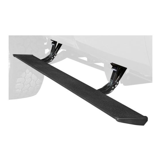
PowerBoard
Automatic Retracting Running Board
www.bestop.com
- We're here to help! Visit our web site and click on
INSTALLATION TIME
4 Hours
TOOLS
13 mm
8 mm,
13 mm
7/32" and
5 mm
SKILL LEVEL
4 - Diffi cult
Vehicle Application
• Ford Super Duty F-250/350/450
Crew Cab
2008 and newer
Part Number: 75134-15
"Ask a
Question". Click here for more
Truck Accessories by Bestop.
Advertisement

Related Manuals for Bestop PowerBoard 75134-15


Summary of Contents for Bestop PowerBoard 75134-15
- Page 1 Part Number: 75134-15 Automatic Retracting Running Board www.bestop.com - We’re here to help! Visit our web site and click on “Ask a Question”. Click here for more Truck Accessories by Bestop. INSTALLATION TIME SKILL LEVEL 4 Hours 4 - Diffi cult TOOLS...
- Page 2 PowerBoard – Installation Instructions Parts List and Hardware Identifi cation M6-1.0 x 30 Socket Running Board Assembly, Qty - 2 Left End Cap, Cap Screw, Part Num- 79" - Part Number 460.87 Part Number ber 460.95, Qty - 6 460.83, Qty - 1 T-Nut Insert, Part Number 460.84, M6 Nut Plate,...
- Page 3 PowerBoard – Installation Instructions Install M8 U-Nuts Install Linkages Counting from the front, locate the second (2nd) and last set of mounting holes Install an Idler Linkage in the on the inner sill on the driver’s side. Use an M8-1.25 x 40 Hex Bolt and an 8mm rear hole and a Motor Linkage in Washer to install an M8 U-Nut on each side of each hole.
- Page 4 PowerBoard – Installation Instructions Connect Controller to Wire Secure Controller and Loom and Wire Harness Wire Harness Connect the Controller to the vehicle wire loom. Connect the Controller power and ground Connect both connectors on the Wire Harness in the to battery, red lead to positive and black parts kit to the connectors on the Controller.
-
Page 5: Driver Side
PowerBoard – Installation Instructions Access Trigger Wire Wiring Pull back the carpet and pull the trigger wires The trigger wires are color coded to match the factory door ajar wires. Use the Posi-Taps to connect the through the grommet. Seal the holes in the grommet trigger wires to the matching door ajar wires. - Page 6 PowerBoard – Installation Instructions Reinstall Kick Panel Install Running Boards Install Lights Mount the Steps to the linkages. Slide the mounting Secure the wires and reinstall the kick panel and Clean the outboard surface T-Nut into position. Install M6-1.0 x 20mm Socket sill plate.
- Page 7 PowerBoard – Installation Instructions PowerBoard Troubleshooting PowerBoard Service Tips Test Doors and PowerBoards Issue: Confirming PowerBoard is functional-black Open the doors to make sure that the PowerBoard • Possible cause controller: drops into position on each side of the vehicle. To test if the red controller (473.11), wire harness, Boards do not operate: Cycle boards several times and then fully tighten...
-
Page 8: Limited Warranty
This warranty gives you specifi c legal rights, and you may also have other rights which vary from state to state. For further information or request for warranty work, please contact: Bestop Inc. Customer Service Toll-Free: (800)845-3567 Main: (303)465-1755 E-mail: csbestop@Bestop.com...
Need help?
Do you have a question about the PowerBoard 75134-15 and is the answer not in the manual?
Questions and answers