Advertisement
Quick Links
Installation Instructions
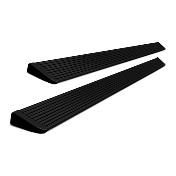
PowerBoard
Automatic Retracting Running Board
www.bestop.com
- We're here to help! Visit our web site and click on
INSTALLATION TIME
3 Hours
TOOLS
13 mm
10 mm,
13 mm
®
NX
Patent Pending
SKILL LEVEL
3 - Moderately Diffi cult
9/32" Drill Bit
5 mm
Vehicle Application
• Chevy Silverado/GMC
Sierra Extended Cab Diesel
2011 and newer
Part Number: 75647-15
"Ask a
Question". Click here for more
• Chevy Silverado/GMC
Sierra Crew Cab Diesel
2011 and newer
Part Number: 75646-15
Truck Accessories by Bestop.
Advertisement

Related Manuals for Bestop powerboard nx


Summary of Contents for Bestop powerboard nx
-
Page 1: Installation Instructions
Automatic Retracting Running Board Patent Pending www.bestop.com - We’re here to help! Visit our web site and click on “Ask a Question”. Click here for more Truck Accessories by Bestop. INSTALLATION TIME SKILL LEVEL 3 Hours 3 - Moderately Diffi cult TOOLS 9/32"... - Page 2 ® PowerBoard NX – Installation Instructions Parts List and Hardware Identifi cation Left End Cap, Running Board Assembly, Qty - 2 M6-1.0 x 20 Socket Cap Part Number 79" - Part Number 460.87 Screw, Part Number 460.83, Qty - 1 T-Nut Insert, Part 72"...
- Page 3 If the system does not operate as stated above see the Troubleshooting and Battery Replacement sections at the end of the instructions or go to our Receiver web site at http://www.bestop.com/support. Rev. E 0713 75646 / 75647 pg. 3...
- Page 4 ® PowerBoard NX – Installation Instructions Heavy Duty Long Bed Only Heavy Duty Trucks Only Steps 2 and 3 are for Install Brake Cable Ring and Parking Brake Install Replacement Brake HD 2500 and 3500 Cable Guide Cable Guides only. For all other vehicles skip to Step 4.
- Page 5 ® PowerBoard NX – Installation Instructions Install Controller and Install Front Idler Linkage Wire Harness Locate the body rib in front of the plastic tank under the right side of the truck. Insert a M8-1.25 x 30mm Use the two (2) 11" Cable Ties to mount the Flange Hex Bolt through the large slot in the Adaptor Plate and thread it loosely into the large fl...
- Page 6 ® PowerBoard NX – Installation Instructions Remove the fuse from the Wiring Harness. Do not ground wrench when engaged with nut. Attach Leads Remove Fuse from Wiring Harness Remove the fuse from the Wiring Harness. Failure to do so could result Attach power lead (RED wire) to in severe electrical shock which could harm the installer and/or damage positive pole on the battery.
- Page 7 ® PowerBoard NX – Installation Instructions Install Running Boards Mount the Steps to the linkages. Slide the mounting T-Nut into position. Install M6-1.0 x 20mm Socket Head Bolts to secure the boards. Use a 5mm Allen Wrench to tighten the bolts. Make sure the board moves up and down freely by hand.
- Page 8 ® PowerBoard NX – Installation Instructions Install Driver’s Side Install Magnet Front Sensor Open the front driver’s side door and Peel the liner off of the Drivers Back Door clean the area where the magnet Side Front Sensor. Position it on Magnet Back Door and sensor will be installed with a...
- Page 9 ® PowerBoard NX – Installation Instructions Test Doors and PowerBoards ® Open and shut each door to make sure the Power- Boards ® deploy and retract. There is a slight delay in the board deployment so make sure they are fully down before stepping on them.
-
Page 10: Power Board
PowerBoard ® NX – Installation Instructions PowerBoard ® NX Troubleshooting Install Magnet Holders Delay in board operation or boards operate Issue: after doors are shut: Peel the liner off the back of a magnet holder and • Possible cause • Magnet is too far away from Sensor place it around the magnet. -
Page 11: Battery Replacement
® PowerBoard NX – Installation Instructions Linkage Component Identifi cation Battery Replacement This device complies with Industry Canada licence- exempt RSS standard(s). Operation is subject to the following two conditions: (1) this device may not Each sensor is powered by a CR2450 3 volt bat- Motor Gear cause interference, and (2) this device must accept Mounting... -
Page 12: Limited Warranty
This warranty gives you specifi c legal rights, and you may also have other rights which vary from state to state. For further information or request for warranty work, please contact: Bestop Inc. Customer Service Toll-Free: (800)845-3567 Main: (303)465-1755 E-mail: csbestop@Bestop.com...
Need help?
Do you have a question about the powerboard nx and is the answer not in the manual?
Questions and answers