Table of Contents
Advertisement
1.
Introduction ..................................................................................... 2 EN
1.1 Attributes ................................................................................... 3 EN
2. Description ........................................................................................ 3 EN
2.1 Central Box 200 ....................................................................... 3 EN
2.2. Central Box 100 ....................................................................... 5 EN
2.3 Magnetic switch ( Central Box 200 only) ............................ 6 EN
3. Connection ...................................................................................... 7 EN
3.1 Power Supply ............................................................................ 7 EN
3.2 Overload protection of servos ............................................ 10 EN
3.3 Connecting Central Box - PPM variant ............................ 11 EN
3.4 Connecting Central Box - EX Bus variant ........................ 12 EN
4. Configuration via JETIBOX ....................................................... 14 EN
4.1 Actual values .......................................................................... 15 EN
4.2 Minimum / Maximum values ............................................. 15 EN
4.3 Setting ..................................................................................... 16 EN
4.4 Out Pin Set ............................................................................... 17 EN
4.5 Alarms .................................................................................... 18 EN
4.6 Service information .............................................................. 19 EN
5. Configuration via the DC/DS transmitter ............................. 20 EN
5.1 General Settings .................................................................... 21 EN
5.2 Fail-Safe .................................................................................. 22 EN
5.3 Servo Output Mapping ....................................................... 23 EN
5.4 Telemetry ............................................................................... 23 EN
5.5 Telemetry Min/Max .............................................................. 24 EN
5.6 Reset to factory settings ...................................................... 24 EN
6. Firmware update ........................................................................... 25 EN
7. Safety precautions for working with magnets ................... 26 EN
8. Technical specifications of the Central Box .......................... 27 EN
9. Warranty, service and the technical support ....................... 28 EN
1 EN
EN
Advertisement
Table of Contents

Related Manuals for JETI model Central Box 200


Summary of Contents for JETI model Central Box 200
-
Page 1: Table Of Contents
2. Description ..................3 EN 2.1 Central Box 200 ............... 3 EN 2.2. Central Box 100 ............... 5 EN 2.3 Magnetic switch ( Central Box 200 only) ......6 EN 3. Connection ..................7 EN 3.1 Power Supply ................7 EN 3.2 Overload protection of servos .......... -
Page 2: Introduction
ENGLISH 1 Introduction The Central Box is a switchboard designed for the complete management of servos in a model with an emphasis on safety. The Central Box has a unique design that provides overload protection at each servo output. The Central Box can manage two batteries and fully supports the JETI EX telemetry system. -
Page 3: Attributes
Possibility to connect up to 2 receivers with serial interface (PPM, EX Bus) • Built-in Expander function for up to 3 sensors • Input for magnetic switch or RC switch (Central Box 200 only) • MPX battery input connector(s): 1x Central Box 100, 2x Central Box 200 •... - Page 4 The Ext1 slot is also used for the firmware update connection (using the USBa). Rx1 - primary input for connecting receivers with serial output (EX bus or PPM) Rx2 - secondary (backup) input for connecting receivers with serial output (EX bus or PPM) Switch input is reserved for connecting a magnetic switch or RC switch (optional accessories).
-
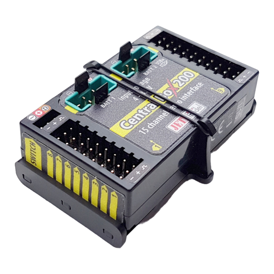
Page 5: Central Box 100
2.2 Central Box 100 The Central Box 100 has 8 servo outputs with overload protection, labeled 1 through 8. OUT/IN – universal input/output for switching additional functions or for supervising the operational status Ext1 – this port can be configured for use as: •... -
Page 6: Magnetic Switch ( Central Box 200 Only)
2.3 Magnetic switch ( Central Box 200 only) The magnetic switch is used to turn the Central Box 200 on or off and is connected to a separate slot labeled “Switch”. To turn on the Central Box using the magnetic switch it is necessary to hold the... -
Page 7: Connection
When turning on, connect the batteries first and then turn the system on via magnetic switch. Keep the same rule when switching off. First switch the system off via magnetic switch and then disconnect the batteries. 3 Connection The Central Box is connected to the power supply, receiver, servos, controller/controllers and eventually sensors. - Page 8 RC Switch Magnetic Switch Rsat2 (Rx2) Rsat2 (Rx1) Input Voltage input voltage 4-14V Fig. 4: Example of the Central Box 200 powered for use with standard servos (voltage range up to 6V) Input Voltage 6V Rsat2 (Rx1) input BATT voltage 4-14V...
- Page 9 Input voltage 8.4V input voltage 4-14V Fig. 6: Example of the Central Box 200 powered for use with HIGH Voltage servos It is not recommended to supply power to the Caution: Central Box through the outputs for servos, sensors or receivers.
-
Page 10: Overload Protection Of Servos
Input Voltage 8.4V Rsat2 (Rx1) input BATT voltage 4-14V Rx 1 Rx 2 Rsat2 (Rx2) Ext. Out/In 8 channel servo interface Fig. 7: Example of the Central Box 100 powered for use with HIGH Voltage servos 3.2 Overload protection of servos The Central Box has an overload protection circuit on every servo output. -
Page 11: Connecting Central Box - Ppm Variant
Channels 14 and 15 can be configured as servo outputs, or as inputs for telemetry sensors ( Central Box 200 only) Configuring the Central Box is in this way done by using a JETIBOX; either directly connected to the Central Box, or wirelessly using a JETI transmitter. -
Page 12: Connecting Central Box - Ex Bus Variant
SERVO/Sensor 4-14V SERVO Fig. 10: Block diagram of Central Box 200 connection - PPM variant 3.4 Connecting Central Box – EX Bus variant Receivers can be connected to the Central Box using the Rx1 and Rx2 inputs. Ext1 is an input for telemetry sensor. Telemetry is transmitted to the receivers via EX Bus. - Page 13 SERVO/Sensor 4-14V SERVO Fig. 12: Block diagram of Central Box 200 connection - EX Bus variant The Central Box can be configured in two ways: • by JETIBOX connection (directly to the Central Box or wirelessly via the transmitter) •...
-
Page 14: Configuration Via Jetibox
4 Configuration via JETIBOX The JETIBOX terminal can be used for parameter setting and retrieving data. After connecting to the Central Box (output Ext1), a startup screen appears that contains identification of the device in the first line of the JETIBOX display. The second line contains the data showing the consumed capacity of batteries 1 and 2. -
Page 15: Actual Values
4.1 Actual values *CENTRAL BOX*: Actual Value – by pushing the D button (down arrow) you select the display of actual measured values • Accu voltage - shows the actual voltage of both inputs • Accu current - displays the actual current flowing from the battery to the output •... -
Page 16: Setting
• Min/Max Temper. - the highest and the lowest temperature of the Central Box during its operation (since the last manual reset) Statistics of the received signal expressed in time R1: how long was the signal from the primary receiver available to the Central Box R2: how long was the signal from the secondary receiver available to the Central Box... -
Page 17: Out Pin Set
1, Y2 is the Central Box labeled 2, etc. • Function – setting of alternative functions of the outputs. This function is available for outputs: Central Box 200 • Y14 and Y15: Servo Output function or Telemetry Input. -
Page 18: Alarms
• FS position – setup of the selected output deflection in case of signal loss • FS speed – setup for how quickly the output transitions to its programmed deflection in case of signal loss • ATV High Limit Yx – sets the upper travel (throw) limit of the output •... -
Page 19: Service Information
4.6 Service information *CENTRAL BOX*: SERVICE – pushing the D button (down arrow) moves you to the display of the firmware version and the menu for restoring the default settings of the Central Box. • PresetToSetup – pushing arrows R and L (right and left) together leads to loading the default settings of the Central Box. -
Page 20: Configuration Via The Dc/Ds Transmitter
Configuration via the DC/DS transmitter The Central Box can be configured by a DC/DS transmitter via the Device Explorer menu. It is necessary to follow these rules for configuring the Central Box via transmitter: - Receiver firmware version Duplex 3.12 and newer (with setting Output mode->EX Bus) - The receiver must be connected to the Central Box via EX bus - Transmitter firmware version 2.02 and newer + the device... -
Page 21: General Settings
5.1 General Settings • Output Period – setting for the period of the output signals (default Auto-synchronous mode with the transmitter). This parameter significantly affects the behavior of the servos. For analog servos the reaction (response) accelerates and the power consumption is higher when the values for the output period are lower. -
Page 22: Fail-Safe
5.2 Fail-Safe • Fail Safe – switches on/off the Fail Safe function. If the Fail Safe function is deactivated, there is no signal generated in any Central Box outputs at the signal loss. If you activate the Fail Safe function, you can also select how the Central Box responds at signal loss for each of the individual outputs (OUT off, hold fail safe).. -
Page 23: Servo Output Mapping
5.3 Servo Output Mapping • Servo No. – assigning outputs of the transmitter to the Central Box outputs (Output pin). • Group – assigns specific output to the group of output impulses that will be generated from the receiver in the same time Fig. -
Page 24: Telemetry Min/Max
5.5 Telemetry Min/Max • Clear Min/Max switch – here you can assign a control (switch, stick or knob) on the DC/DS transmitter which clears the recorded battery capacity and minimum/maximum values in the Central Box. • Clear Now – allows you to immediately clear the recorded battery capacity and minimum/maximum values in the Central Box. -
Page 25: Firmware Update
Start the firmware update program for the Central Box on your For Central Box 100: Connect the Central Box to the power supply. For Central Box 200: Switch on the Central Box using the magnetic switch or the RC switch. The USB-adapter driver installation instructions can be found in the USB-adapter instruction booklet. -
Page 26: Safety Precautions For Working With Magnets
8 channel servo interface USBa Safety precautions for working with magnets Because the Central Box 200 is put into operation via magnet, it is necessary to follow safety precautions for handling magnets. The magnet is mounted in a hard aluminum carrier. -
Page 27: Technical Specifications Of The Central Box
Technical specifications of the Central Box Technical specifications of the Central Box Recommended input voltage 4 – 14 V Number of connectable accu cells 2-3 LiXX or 4-10 NiXX Continuous current 10 A Output pulse current 90 A Number of servo outputs up to 8 Operating temperature - 20°C up to +75°C... -
Page 28: Warranty, Service And The Technical Support
You can contact either your dealer, or directly the manufacturer JETI model s.r.o.. For further information see our webpages www.jetimodel.com. We wish you sucessful flying with the products of: JETI model s.r.o. Příbor, www.jetimodel.com 28 EN... - Page 29 Declaration of Conformity Declaration of conformity in accordance with the Statutory rules n. 426/2000 sb. and Directive 1999/5/EC Issues name & addres: JETI model s.r.o. Lomena 1530, 742 58 Pribor Object of the declaration: Products: Servo interface Trade name: Central Box...
- Page 30 30 EN...
Need help?
Do you have a question about the Central Box 200 and is the answer not in the manual?
Questions and answers