
Related Manuals for JETI model Duplex DS-12


Summary of Contents for JETI model Duplex DS-12
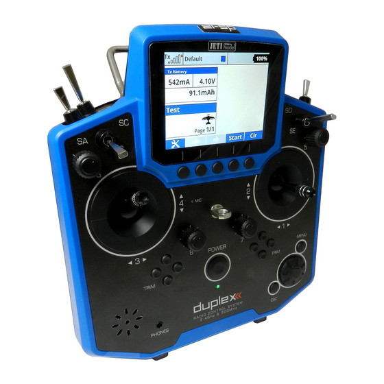
- Page 1 computer radio control system CZECH REPUBLIC DS -12 2.4GHz & 900MHz NG Dual Band System FW 5.xx...
- Page 2 computer radio control system...
-
Page 3: Table Of Contents
4.3.4 Ratchet Tension Adjustment ..........18 1.1 DS-12 ....................09 4.3.5 Throttle stick travel adjustment ........19 1.2 Activation method for software modules of JETI model ..09 1.3 Features ..................... 11 4.3.6 Changing the transmitter mode ........19 1.4 Manual Navigation ................ 12 4.4 Swappable and Assignable Switches ........ - Page 4 computer radio control system 8.2 Installation ..................42 6. Transmitter Powering ON/OFF ............28 8.3 Binding ....................42 6.1 Transmitter, Powering-ON ............28 6.2 Transmitter Turning-OFF ............... 28 8.3.1 Standard pairing procedure ..........42 6.3 Transmitter Restart ..............28 8.3.2 Alternative pairing procedure through the transmitter menu ..........
- Page 5 computer radio control system 10. Battery Safety Handling Rules ............133 10.1 Transmitter Battery Pack ............133 10.2 General Safety Rules ..............133 10.3 Flight Safety Check ..............134 10.4 Application ..................134 10.5 FCC /IC Information ............... 134 The following chapters are only included in the electronic version of the manual.
- Page 6 computer radio control system...
- Page 7 computer radio control system...
- Page 8 computer radio control system...
-
Page 9: Introduction
1 Introduction Activation method for software modules of JETI model 1.1 DS-12 Make sure you have the most current firmware version in your The DS-12 transmitter was developed and produced with the transmitter. cooperation of professional engineers and world champion pilots. - Page 10 computer radio control system the relevant amount. After payment, a unique nontransferable file named “Activation.bin” will be generated. It will then be sent to your e-mail. Connect the DS-14 to your computer and enable USB mode. Copy the “Activation.bin” file to the transmitter SD card into the root folder.
-
Page 11: Features
Large Memory – Internal SD card for storing models, sounds, and frequency hopping, digital, data stream system, originally telemetry data. developed by JETI model in the Czech Republic. This system has USB Connector – convenient connection to your PC. Fast firmware & been reliably used for many years. -
Page 12: Manual Navigation
CZ distributor or dealer. Third party transactions are not covered by this warranty. Proof of purchase is required for warranty claims. Repair or replacement decisions are at the sole discretion of JETI model CZ or an authorized service provider. This warranty does not cover cosmetic... -
Page 13: Package Contents
computer radio control system 1.6 DS-12 Package Contents 2 System Specifications JETI DS-12 Transmitter, Wall Power Supply, USB PC Cable, Installation Key Set (HEX 1,5; TORX 10) Cleaning Cloth, Instruction Basic technical parameter DS-12 Manuals, RF module 900MHz (863-870 MHz - EU) (902-928 MHz - US) Stick material Multimode Plastic... -
Page 14: Help Mode
computer radio control system This help mode is available in FW min. v5.00. We recommend update 3 Help mode your transmitter by Jeti Studio. It is possible to call up the help mode for each item where a "question mark" icon appears in the upper right corner of the screen . -
Page 15: Description Of Transmitter Ds-12
computer radio control system 4 Description of Transmitter DS-12 4.1 Control Identification DS-12 Right Stick 1, 2 – the DS-12 Transmitter Supports Modes 1-4, see Control Sticks -> mode change Left Stick 3, 4 the DS-12 Transmitter Supports Modes 1-4, see Control Sticks ->... -
Page 16: Assembly Identification
computer radio control system 4.2 Assembly Identification Battery Connector Micro SD Card Transmitter Battery Pack 2.4GHz Antennas PPM Output Connector 900 MHz Antenna Left Gimbal Assembly Right Gimbal Assembly... -
Page 17: Control Stick Assembly
computer radio control system If you have installed optional sticks with switch or 4.3 Control Stick Assembly Warning: button ends; make sure that while adjusting the stick length you observe the wires that pass through the Note: When handling with back cover removed always stick shaft and through the gimbal opening in order switch off the transmitter and disconnect the to prevent damaging the connecting cables. -
Page 18: Ratchet Tension Adjustment
computer radio control system Use indicated machine adjustment screws to change the For ratchet tension adjustment use the machine screw “A” desired spring tension. By turning the screw countercloc Turn slowly (counter-clockwise) until you achieve the desired kwise, you will loosen spring tension. As a result the moving ratchet tension. -
Page 19: Throttle Stick Travel Adjustment
computer radio control system 4.3.5 Throttle stick travel adjustment 4.3.6 Changing the transmitter mode The transmitter is equiped with universal multimode gimbals. Both The throttle stick travel is adjustable to suit your flying style. gimbals are identical and can be adjusted mechanically for modes 1- 5. - Page 20 computer radio control system B. Setting the multi-mode gimbal into the mode with locking the middle position - elevator Loosen the screw Slightly lift the lever Turn the lock in the direction of the arrow and arrest the lever in the upper position. Move the lever in the direction of the arrow to release the lever Tighten the screw Loosen the screws E and D in a position so that tension is removed...
-
Page 21: Swappable And Assignable Switches
computer radio control system 4.4.1 Switch Removal Procedure 4.4 Swappable and Assignable Switches Switch off the transmitter and remove the 7 screws that secure the radio back cover. Next, remove the radio back cover. One of the most important features of a JETI transmitter is the switch Be sure to disconnect the transmitter battery pack function assignment flexibility. -
Page 22: Assembly Procedure
computer radio control system Disconnect the flat flexible cable from its connector on the After you turn on the transmitter for the first time after any switches main board. have been modified, you will notice that the configuration for a selected model no longer matches. -
Page 23: Digital Trims
computer radio control system 4.6 Transmitter Battery Pack 4.5 Digital Trims Transmitter gimbals are used for controlling the basic flight The DS-12 transmitter is powered by a Li-Ion type battery pack and functions like throttle, roll(aileron), pitch(elevator), and yaw(rudder). comes equipped with its own built-in advanced battery Immediately under the transmitter gimbal sticks you can see four management and charging circuit. -
Page 24: Battery Replacement
computer radio control system 4.6.2 Battery Replacement 4.7 PPM Input/Output Connector Should you decide to replace the transmitter battery, please follow these steps: The PPM output is accessible via connector labeled "B“. This connector features the non-stabilized battery voltage output in the Switch off the transmitter and remove the 7 screws that range of 3.2V - 4.2V (max. -
Page 25: Handling
computer radio control system 4.8 Handling 4.9 Change SD Card The DS-12 is equipped with a handle for practical manipulation as Disconnect the battery plug . shown in the picture. To open the SD card holder, use a fingernail to push the metal frame to the right and then lift it carefully . -
Page 26: Rf Transmitter Modules
computer radio control system • 5 RF Transmitter Modules Back-up Transmitter Module The DS-12 are equipped with a wireless backup system . This works on the 868MHz ( EU ) or 915MHz ( US, AU, JP ) band . This In order to achieve the highest transmission quality and reliability of backup system can optionally be used to the "standard"... - Page 27 computer radio control system Recommended connection for Rsat900 NG as a backup receiver Connecting the RSat 900 NG directly to a Primary receiver : with a Central Box • The RSat900 receiver is plugged into the “Sat1” slot of the primary •...
-
Page 28: Transmitter Powering On/Off
computer radio control system 6 Transmitter Powering ON/OFF 6.2 Transmitter Turning-OFF The transmitter is switched-off by pressing the "Power“ main 6.1 Transmitter Powering-ON button. Before complete power-down is achieved you will be asked for additional confirmation. In case of an emergency, a fast turn-off Switching-on is achieved by pressing and holding the "Power“... -
Page 29: Initial Switching-On
computer radio control system 7 Initial switching-on 7.1 Main display Turn the transmitter on by pressing and holding the „Power“ button The main screen displays basic information about operation of your for a couple of seconds and then press the "F5 (Yes)" button to transmitter, such as the battery level, time, flight mode, etc. -
Page 30: Navigation In The Menu
computer radio control system The lower bar is found at the bottom of the main display. 7.2 Navigation in the Menu The lower bar shows: 7.2.1 Navigation The „menu“ button allows you to switch between the main display and the transmitter‘s main menu. Also, If you push this button while turning the 3D Control Advice: Selector to edit values, the values can be changed faster. -
Page 31: Browsing Through The Menu
computer radio control system 7.2.3 Basic Menu Structure * Model - Telemetry Controls - Select Model - Voice Commands - New Model - Sequencer - Accelerometer - Basic Properties - Model Image & Colors * Timers/Sensors - Functions Assignment - Timers - Servo Assignment - Alarms - Servo Setup... -
Page 32: Model Set-Up Guide
computer radio control system 7.3 Model Set-up Guide Warning: For safety reasons we recommend first removing the propeller. In this section we will guide you, step by step, through the process of Switch-on the transmitter. In the main creating a new model airplane and helicopter. Each step of the guide display push the key „menu“. - Page 33 computer radio control system Select your wing type. Because this The screen will now display a request which example has 2 aileron servos, select „Wing asks if you really want to create and activate type“ 0FLP/2WING. Do not change any the new model.
-
Page 34: Helicopter
computer radio control system From the main screen, push the „menu“ 7.3.2 Helicopter button. Select „Fine tuning“ and push the Let’s create a simple model helicopter. In this example, the „3D button“. helicopter is controlled by a swash plate with three servos at 120° orientation and the motor has no governor. - Page 35 computer radio control system Select the helicopter swash plate type"3 Switch on the transmitter. In the main servos (def 120°)“. Change the second display push the key "menu“. Select the menu item "Position of front servo“ to item "Model“ and push the "3D button“. "Rear“...
-
Page 36: Multicopter
computer radio control system In the "Fine tuning -> Flight modes“ menu you will setup these The "Swash Mix“ menu displays the travel advanced model control functions for your helicopter: range of each particular helicopter flight function for the swash plate for flybarred Collective pitch curve, see: Fine tuning ->... - Page 37 computer radio control system Servo assignment to receiver channels: Select the item „New model“ and push Throttle the „3D button“. Roll (ailerons) Pitch (elevator) Yaw (rudder) Mode (multicopter mode channel) Enter the name of your model and press Before you begin creating a model, make sure that you have setup „F5(OK)“...
-
Page 38: General
computer radio control system This page displays the flight control Bind transmitter with the receiver, see chapter 8.3 Receiver- functions and their transmitter switch >Binding. Once your transmitter has been bound with the receiver assignments. Here you can verify that your and you have re-applied power to the receiver, the last setup phase is flight control functions are correctly the tuning of your flight controller channels, see chapter 7.3.5... - Page 39 computer radio control system Before creating a model, make sure that you have setup the correct Choose an optional model image and transmitter mode in "Main menu -> System -> Configuration -> color profile according to your personal MODE 1-4“. The basic, standardized, assignment of transmitter preferences.
- Page 40 computer radio control system (spring-loaded switch). After you create all of your desired functions, Once your transmitter has been bound with a receiver and has been press the „F5(Next)“ button to confirm. connected to its power supply, the last step consists of tuning the servo output functions, see chapter 7.3.5: Setup of receiver The "Servo assignment“...
-
Page 41: Setup Of Receiver Outputs
computer radio control system 7.3.5 setup of Receiver Outputs their full travel. You should use the dual rate function to set your model’s useable control throws. Go to the "Model->Servo Setup“ menu. Use the "F2“ and "F3“ buttons to brows through the receiver outputs (channels). You can scrol through the following servo adjustment items for each channel: „Servo reversing“... -
Page 42: Duplex Receivers
computer radio control system 8 Receiver A1/A2 - receiver antennas. The antennas should be installed so that the wires form a 90° angle relative to each other. 8.1 Description 8.2 Installation Whenever possible, you should wrap the receiver in foam and place it as far as possible from sources of interference (servos, electric motors). -
Page 43: Alternative Pairing Procedure Through The Transmitter Menu
computer radio control system 8.3.2 Alternative pairing procedure through the 8.4 Range Test transmitter menu The range test will verify that the transmitter and receiver are functioning properly. Turn off the receiver. Keep the transmitter turned on. Before the first flight of each flying session or if have any doubts Plug the "BIND PLUG"... - Page 44 computer radio control system Each receiver channel can be configured to one of the modes described above. We recommend that you setup "fail safe“ positions for every output, which enables your model to stay in a stable condition. For instance, the elevator and rudder in neutral positions, electric motor switched-off, gas engine idling, spoilers extended.
-
Page 45: Using Device Explorer To Configure The Receiver
computer radio control system In the picture above, two receivers have been detected and are Using Device Explorer To Configure the Receiver recognized. When you press the rotary button, you are able to configure them in detail. Here is the example how to use the Device The Device Explorer utilizes the latest Explorer to configure an "R9 EX"receiver: data/command EX Bus protocol to... - Page 46 computer radio control system - Reset to factory defaults... – After confirmation, the receiver's Note: Before a device can be recognized, a special predefined configuration will be restored to its factory settings. configuration scheme must be present on the SD card in the /Devices folder.
- Page 47 computer radio control system - PPM/UDI Mode - determines processing and additional logic moment of losing signal until the fail-safe is activated. This option is applied to the PPM and UDI protocols. available only if the Individual mode is selected. - Direct - signals received from the transmitter are not further on - Each output position of the receiver has three adjustable processed in the receiver, they are generated without any change at...
-
Page 48: Support Of Remote Commands For Ex Bus Devices
computer radio control system The page Receiver Outputs (picture )) allows you to redirect your The screen , "Alternative Pin Config", allows you to modify the transmitter’s channels to any output of the receiver. For convenience modes of receiver output pins. The servo outputs can be configured the transmitter’s channel numbers are displayed together with the into Digital input and Digital output modes. - Page 49 computer radio control system On the main screen of the Central Box settings scroll down to display The list of active commands. the maximum telemetry values (Telemetry Min/Max). Here you will find a choice to assign a switch to the command for deleting measured minimums and maximums (Clear Min/Max switch).
-
Page 50: Rc-Switch
computer radio control system Variant of the RC Switch Note: This text describes receiver properties introduced in DS- Power In 12 V3.0 and receivers version 3.25. Earlier versions of the Power Out firmware might offer different properties, or the Receiver battery RC Switch RC Power Switch described configuration might be entirely inaccessible. - Page 51 computer radio control system...
-
Page 52: Transmitter To Pc Connection
computer radio control system 9 Transmitter to PC Connection 9.2 Update firmware The JETI Duplex line of transmitters are equipped with a mini USB The JETI Duplex line of transmitters fully support future software port. The Transmitters also come with a standard USB to mini USB updates. -
Page 53: System Backup
computer radio control system 9.4 System Backup 9.7 Copying models between the transmitters Data backup is as easy as the standard backup you can perform on Configuration of all models in the transmitter are stored on the your PC. You can save all your data onto a PC hard drive or CD. The internal SD card in the directory /Model/. - Page 54 computer radio control system 10 Battery Safety Handling Rules 10.2 General Safety Rules 10.1 Transmitter Battery Pack Any repair, installation, or upgrade must be performed with caution and common sense. These will The Installed battery pack must be charged from an AC voltage require some basic mechanical skills.
- Page 55 computer radio control system Do not point the transmitter antenna directly towards your direction of movement for your flight surfaces. model or a human body. The radiation pattern from the antenna will Set motor/engine kill switch and test the power train. be shielded and provide poor connection to your model.
- Page 56 computer radio control system radioélectrique à l'intention des autres utilisateurs, il faut choisir le THIS DEVICE COMPLIES WITH PART 15 OF THE FCC RULES. type d'antenne et son gain de sorte que la puissance OPERATION IS SUBJECT TO THE FOLLOWING TWO CONDITIONS(1) isotroperayonnée équivalente (p.i.r.e.) ne dépasse pas l'intensité...
- Page 57 computer radio control system...
- Page 58 computer radio control system...
- Page 59 computer radio control system...
- Page 60 ® JETI model s.r.o. Lomená 1530, 742 58 Příbor www.jetimodel.com Made in Czech Republic...
Need help?
Do you have a question about the Duplex DS-12 and is the answer not in the manual?
Questions and answers