Table of Contents
Advertisement
Advertisement
Table of Contents

Related Manuals for JETI model Duplex DS-16


Summary of Contents for JETI model Duplex DS-16
- Page 1 computer radio control system CZECH REPUBLIC DC-16, DS-16, DS-14 FW 3.00...
-
Page 2: Table Of Contents
1.1 DC/DS ....................07 3.3.1 Control Stick Length Adjustment ........17 1.2 DS-14 ....................07 1.2.1 Activation method for software modules of JETI model 08 3.3.2 Swivel Control Stick Adjustment ........17 1.3 Features ..................... 09 3.3.3 Control Stick Tension Adjustment ........18 3.3.4 Ratchet Tension Adjustment .......... - Page 3 computer radio control system 4.7.1 Charging ................40 4. Description of Transmitter DS-16 ............ 26 4.7.2 Battery Replacement ............40 4.1 Control Identification ..............26 4.2 Control Identification DS-14 ............27 4.8 PPM Output Connector ..............41 4.3 Assembly Identification ..............28 4.9 Handling ..................
- Page 4 computer radio control system 7.3.2 Helicopter ................49 8.8 RC-Switch ..................65 7.3.3 General ..................51 7.3.4 Set up of Receiver Outputs ..........53 9. Main menu ....................67 9 . 0 . 1 Pa s s w o r d p r o t e c t i o n a g a i n s t a c c i d e n t a l 8.
- Page 5 computer radio control system 9.2.2 Digital trim ................83 9.3.5 Sounds on Event (Sound Assignments) ......109 9.2.3 Flight Mode Trims ..............85 9.3.6 Sequencer ................110 9.2.4 Dual Rate/Exponential ............86 9.3.7 Accelerometer (DS only) ........... 111 9.2.5 Programmable Function Curves ........88 9.3.8 Telemetry Controls ..............
- Page 6 computer radio control system 9.6 System .................... 127 10.2 Update Firmware ............... 140 9.6.1 Configuration ..............127 10.3 Sounds, Alarms & Acoustic Updates ........140 9.6.2 Servo & Range Test ............. 129 10.4 System Backup ................141 9.6.3 View Inputs ................130 10.5 PC Joystick ..................
- Page 7 computer radio control system 12.4 V-Tail Mix ..................146 13.5 Charging ..................157 12.5 Delta/Elevon Mix ................147 13.6 Other ....................157 12.6 Spoilers to Elevator Mix ............. 147 13.7 O v e r v i e w o f t h e D S - 1 4 e x p a n s i o n m o d u l e s 12.7 Ailerons to Rudder Mix ..............
-
Page 8: Introduction
computer radio control system 1 Introduction 1.2 DS-14 1.1 DC/DS The DS-14 hand-held transmitter expands the range of model The DC/DS transmitters were developed and produced with the transmitters equipped with the JETI Duplex system, this new design cooperation of professional and world champion pilots. These is based on the high-end model DS-16. -
Page 9: Activation Method For Software Modules Of Jeti Model
It will then be sent to your e-mail. 1.2.1 Activation method for software modules of JETI model Connect the DS-14 to your computer and enable USB mode. Make sure you have the most current firmware version in your transmitter. -
Page 10: Features
USB Connector – convenient connection to your PC. Fast firmware & frequency hopping, digital, data stream system originally developed sound upgrades, telemetry data downloads. by JETI model in the Czech Republic. This system has been reliably Fast Navigation – 3D wheel-style interface combined with function used for many years. -
Page 11: Table Of Contents
computer radio control system 1.4 Table of Contents extended functions from swshop.jetimodel.com. To make navigation faster, the DC/DS transmitter Instruction Manual has been divided into 5 basic groups: Introduction and product support. Basic description and mechanical adjustments. First time switch-on. Basic helicopter and airplane set up. Advanced programming. -
Page 12: Technical Support
Third party transactions are not covered by this warranty. Proof of purchase is required for warranty claims. Repair or replacement decisions are at the sole discretion of JETI model CZ or an authorized service provider. This warranty does not cover cosmetic damage or damage due to an accident, misuse, abuse, negligence, commercial or research use, or modification of or to any part of the product. -
Page 13: Package Contents
computer radio control system 1.7 DS-16 Package Contents 1.8 DS-14 Package Contents JETI DS-16 Transmitter, Wall Power Supply, JETI DS-16 JETI DS-14 Transmitter, Wall Power Supply, USB PC Cable, Installation Hex Key Set (1,5mm; 2mm), Instruction Manuals. Transmitter Aluminum Case, USB PC Cable, Installation Hex Key Set (1,5mm;... -
Page 14: System Specifications
computer radio control system 2 System Specifications 2.1 DC-16 2.2 DS-16 Frequency 2.4GHz Frequency 2.4GHz 180x270x40 mm 194x172x40 mm Dimensions Dimensions 7.1x10.6x1.6", 7.7x6.8x1.6" WxLxH WxLxH (230x270x40mm) (194x233x40 mm) (with Antenna) (with Display) (9.1x10.6x1.6") (7.7x9.2x1.6") Weight 1.5kg (53 oz) Weight 1.25kg (44 oz) Number of Channels Number of Channels Number of control directions... - Page 15 computer radio control system Modules Software Base Extended 2.3 DS-14 Nombre de voies Frequency 2.4GHz Accéléromètre Module UHF secondaire intégré 194x172x40 mm fonction Dimensions 7.7x6.8x1.6" Moniteur/Elève ou„Double Path“ WxLxH (194x233x40 mm) Nombre de phase de vol (with Display) (7.7x9.2x1.6") Mixeurs libres Analyse de la télémétrie par des graphes Weight 1.25kg (44 oz)
-
Page 16: Description Of Transmitter Dc-16
computer radio control system 3 Description of Transmitter DC-16 3.1. Control Identification Right Stick 1, 2 – the DC-16 Transmitter Supports Modes 1-4, see Control Sticks -> mode change Left Stick 3, 4 the DC-16 Transmitter Supports Modes 1-4, see Control Sticks ->... -
Page 17: Assembly Identification
computer radio control system 3.2. Assembly Identification Battery Connector Transmitter Battery Pack PPM Output Connector Left Gimbal Assembly Right Gimbal Assembly... -
Page 18: Control Stick Assembly
computer radio control system 3.3 Control Stick Assembly Warning: If you have installed optional sticks with switch or button ends, make sure that while adjusting the stick length you observe the Note: When handling with back cover removed always wires that pass through the stick shaft and through the gimbal switch off the transmitter and disconnect the opening in order to prevent damaging the connecting cables. -
Page 19: Control Stick Tension Adjustment
computer radio control system Loosen both machine screws securing the control stick decrease. By turning the screw clockwise, you will tighten assembly. spring tension. As a result the moving resistance of the control stick will increase. Adjust (rotate) to desired position. Securely tighten both machine screws securing the control stick Reconnect transmitter battery pack and reinstall radio back assembly. -
Page 20: Throttle Stick Travel Adjustment
computer radio control system the desired smooth tension. Reconnect transmitter battery pack and reinstall radio back 3.3.6 Transmitter Mode Switch cover and cover screws. The DC-16 transmitter allows you to switch between Mode 1, 2, 3 and 4 stick configurations with just few simple steps. In order to do some of these, the stick control assemblies will need to be swapped. -
Page 21: Transmitter Gimbals With Switch Or Button Installation
computer radio control system It may be necessary to remove the screws securing the RF circuit Note: board to release the wire group. After making a mode switch you must re-calibrate the transmitter stick assemblies and setup the correct mode Remove both machine installation screws for each of the in the software menu, see section 9.6.1 –... - Page 22 computer radio control system X Y S Adjust length of the stick to suit your flying style. (See 4.3) Disconnect the control stick assembly wires from the Tx board. Note: After installation of the optional stick ends with switch or (3 wires X, Y, S button make sure that while adjusting the stick length you...
-
Page 23: Swappable And Assignable Switches
computer radio control system 3.4 Swappable and Assignable Switches One of the most important features of a JETI transmitter is the switch function assignment flexibility. The DC-16 transmitter automatically detects the type of switch and assigns the selected function. The following switch types are available: •... -
Page 24: Digital Trims
computer radio control system Switch Exchange: 3.5 Digital Trims Switch off the transmitter and remove the 10 screws that secure Transmitter gimbals are used for controlling the basic flight the radio back cover. Next, remove the radio back cover. functions like throttle, roll(aileron), pitch(elevator), and yaw(rudder). Be sure to disconnect the transmitter battery pack Immediately under the transmitter gimbal sticks you can see four connector. -
Page 25: Transmitter Battery Pack
computer radio control system 3.6.2 Battery Replacement 3.6 Transmitter Battery Pack Should you decide to replace the transmitter battery, please follow The DC-16 transmitter is powered by a Li-Ion type battery pack and these steps: comes equipped with its own built-in advanced battery Switch off the transmitter and remove the 10 screws that management and charging circuit. -
Page 26: Ppm Output Connector
computer radio control system 3.7 PPM Input/Output Connector 3.8 Handling The DC-16 transmitter can be comfortably carried by holding it for The PPM output is accessible via connector labeled „B“. This the antenna cover/handle as shown on the picture. connector features the non-stabilized battery voltage output in the range of 3.2V - 4.2V (max. -
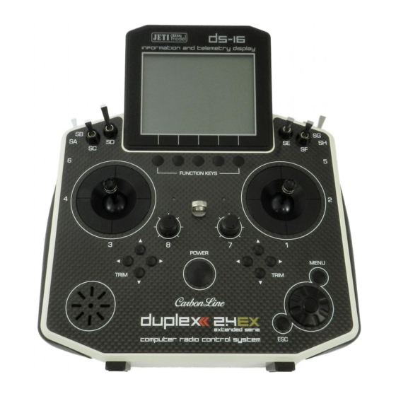
Page 27: Description Of Transmitter Ds-16
computer radio control system 4 Description of Transmitter DS 4.1 Control Identification DS-16 Right Stick 1, 2 – the DS-16 Transmitter Supports Modes 1-4, see Control Sticks -> mode change Left Stick 3, 4 the DS-16 Transmitter Supports Modes 1-4, see Control Sticks ->... -
Page 28: Control Identification Ds-14
computer radio control system 4.2 Control Identification DS-14 Right Stick 1, 2 – the DS-14 Transmitter Supports Modes 1-4, see Control Sticks -> mode change Left Stick 3, 4 the DS-14 Transmitter Supports Modes 1-4, see Control Sticks -> mode change Swappable and Assignable Switches: Sa, Sb, Sc, Sf, Sg, Sh Digital Trims for the Left Stick T3, T4 Digital Trims for the Right Stick T1, T2... -
Page 29: Assembly Identification
computer radio control system 4.3 Assembly Identification DS-14 Battery Connector Transmitter Battery Pack PPM Output Connector Left Gimbal Assembly Right Gimbal Assembly DS-16... -
Page 30: Control Stick Assembly
computer radio control system If you have installed optional sticks with switch or 4.4 Control Stick Assembly Warning: button ends; make sure that while adjusting the stick length you observe the wires that pass through the Note: When handling with back cover removed always stick shaft and through the gimbal opening in order switch off the transmitter and disconnect the to prevent damaging the connecting cables. -
Page 31: Control Stick Tension Adjustment
computer radio control system Loosen both machine screws securing the control stick decrease. By turning the screw clockwise, you will tighten assembly. spring tension. As a result the moving resistance of the control stick will increase. DS-16 DS-16 DS-14 DS-14 Adjust (rotate) to desired position. -
Page 32: Ratchet Tension Adjustment
computer radio control system 4.4.5 Throttle stick travel adjustment 4.4.4 Ratchet Tension Adjustment Do you prefer smooth throttle feel or ratchet throttle feel? You can The throttle stick travel is adjustable to suit your flying style. adjust the DS-16 transmitter either way you like allowing you to fully Switch off the transmitter and remove the 8 screws that secure the customize your radio‘s handling. - Page 33 computer radio control system After making a limit change to the throttle stick travel you must re- calibrate the transmitter stick in the software menu, see section 9.6.3 –Calibration of Proportional Controls.
-
Page 34: Transmitter Mode Switch
computer radio control system Disconnect the control stick assembly wires from the Tx board. 4.4.6 Transmitter Mode Switch (3 wires X, Y , S The DS-16 transmitter allows you to switch between Mode 1, 2, Remove the stick assembly connecting wires from their holders 3 and 4 stick configurations with just few simple steps. -
Page 35: Transmitter Gimbals With Switch Or Button Installation
computer radio control system Reinstall and secure the machine screws for each of the control 4.4.7 Transmitter Gimbals with Switch or Button stick assemblies. Installation If you want to operate the DS-16 transmitter using the optional stick Connect the control stick assembly wires to the Tx board end switch or button functions, you must purchase one or more of connector (3 wires X, Y ,... - Page 36 computer radio control system Remove both installation machine screws for each of the control stick assemblies. Carefully remove both control stick assemblies. Gently lift in your direction (toward the transmitter back side). Unscrew the upper part of the stick assembly (anticlockwise). Insert the connecting wires through the hollow opening of the transmitter stick.
- Page 37 computer radio control system Connect the control stick assembly wires to the Tx board you observe the wires that pass through the stick shaft and connector (3 wires X, Y, S ). Pay close attention to the wire through the gimbal opening in order to prevent damaging lengths.
-
Page 38: Swappable And Assignable Switches
computer radio control system 4.5 Swappable and Assignable Switches Warning: You should keep the wire placement as shown in the picture. The wires must be placed as far as possible One of the most important features of a JETI transmitter is the switch from the magnetic element Please avoid function assignment flexibility. -
Page 39: Switch Removal Procedure
computer radio control system Disconnect the flat flexible cable from its connector on the 4.5.1 Switch Removal Procedure main board. Switch off the transmitter and remove the 8 screws that secure the radio back cover. Next, remove the radio back cover. The flat flexible cables that link the main printed circuit board Be sure to disconnect the transmitter battery pack with the switches are oriented as shown in the picture... -
Page 40: Digital Trims
computer radio control system After you turn on the transmitter for the first time after any switches 4.6 Digital Trims have been modified, you will notice that the configuration for a selected model no longer matches. Transmitter gimbals are used for controlling the basic flight functions like throttle, roll(aileron), pitch(elevator), and yaw(rudder). -
Page 41: Transmitter Battery Pack
computer radio control system 4.7.2 Battery Replacement 4.7 Transmitter Battery Pack Should you decide to replace the transmitter battery, please follow The DS-16 transmitter is powered by a Li-Ion type battery pack and these steps: comes equipped with its own built-in advanced battery Switch off the transmitter and remove the 8 screws that management and charging circuit. -
Page 42: Ppm Output Connector
computer radio control system 4.8 PPM Input/Output Connector 4.9 Handling The DS-16 is equipped with a metal handle for practical The PPM output is accessible via connector labeled „B“. This manipulation as shown in the picture. connector features the non-stabilized battery voltage output in the range of 3.2V - 4.2V (max. -
Page 43: Rf Transmitter Modules
computer radio control system the „Instructor“ mode, the primary RF module communicates 5 RF Transmitter Modules with the model and the secondary RF module communicates with the student’s transmitter. In the „Student“ mode the In order to achieve the highest transmission quality and reliability of DC/DS transmitter communicates via the primary RF module the DC/DS transmitters, we have decided to equip the radio with two with the instructor’s transmitter. -
Page 44: Transmitter Powering On/Off
computer radio control system 6 Transmitter Powering ON/OFF 6.2 Transmitter Turning-OFF The transmitter is switched-off by pressing the „Power“ main 6.1 Transmitter Powering-ON button. Before complete power-down is achieved you will be asked for additional confirmation. In case of an emergency, a fast turn-off Switching-on is achieved by pressing and holding the „Power“... -
Page 45: Initial Switching-On
computer radio control system 7 Initial switching-on 7.1 Main display Turn the transmitter on by pressing and holding the „Power“ button The main screen displays basic information about operation of your for a couple of seconds and then press the "F5 (Yes)" button to transmitter, such as the battery level, time, flight mode, etc. -
Page 46: Navigation In The Menu
computer radio control system The lower bar is found at the bottom of the main display. 7.2 Navigation in the Menu The lower bar shows: To navigate within the transmitter menus, use the following buttons: The „menu“ button allows you to switch between the main display and the transmitter‘s main menu. -
Page 47: Browsing Through The Menu
computer radio control system Note: For each press of the „esc“ button, you are taken back one menu level. 7.2.2 Basic Menu Structure * Model - Sound on Event - Select Model - Sound of Prop. Controls - Telemetry Controls - New Model - Sequencer - Basic Properties... -
Page 48: Model Set-Up Guide
computer radio control system 7.3 Model Set-up Guide Warning: For safety reasons we recommend first removing the propeller. In this section we will guide you, step by step, through the process of Switch-on the transmitter. In the main creating a new model airplane and helicopter. Each step of the guide display push the key „menu“. - Page 49 computer radio control system This page displays the flight control Bind transmitter with the receiver, see chapter 8.4 Receiver->Binding. functions and their transmitter switch Once your transmitter has been bound with the receiver and you have assignments. Here you can verify that your re-applied power to the receiver, the last setup phase is the tuning of flight control functions are correctly assigned your servo output functions, see chapter 7.3.4 Setup of receiver...
-
Page 50: Helicopter
computer radio control system Note: When setting up your spoilerons be sure that the ailerons still Switch on the transmitter. In the main have enough travel to control your airplane when the spoilerons display push the key „menu“. Select the are deployed. - Page 51 computer radio control system When you create a new helicopter model, you are required to define also activate a cyclic reduction of the rotor head travels (Swash Ring) the swash plate configuration for the model. Please refer to your so the servos cannot be damaged by large simultaneous movements helicopter’s instructions and verify that you have the correct swash of the sticks.(Refer to your helicopter’s instruction manual.) Press the plate configuation.
-
Page 52: General
computer radio control system Dual rates, see: Fine tuning -> Flight Modes -> Dual Rate/Expo Servo assignment to receiver channels: Autorotation, see: Fine tuning -> Flight Modes Motor Gyro/Governor see: Fine tuning -> flight modes -> Gyro/Governor Rudder For convenience, a quick link to all of these function settings has been Motor Sound Module made through the Heli Tuning menu. - Page 53 computer radio control system (spring-loaded switch). After you create all of your desired functions, Enter the name of your model and press press the „F5(Next)“ button to confirm. „F5(OK)“ (Note: you must enter a model name to proceed.) Then select the model The „Servo assignment“...
-
Page 54: Setup Of Receiver Outputs
computer radio control system 7.3.4 setup of Receiver Outputs Once your transmitter has been bound with a receiver and has been connected to its power supply, the last step consists of tuning the Go to the „Model->Servo Setup“ menu. Use the „F2“ and „F3“ servo output functions, see chapter 7.3.4: Setup of receiver buttons to brows through the receiver outputs (channels). - Page 55 computer radio control system „Max/Min. limit“ – sets the absolute maximum servo output throw Use these to limit the maximum range of servo throw in order to keep your servos from exceeding their mechanical limits or to keep your servos from binding when moving their arms or linkages to their full travel.
-
Page 56: Duplex Receivers
computer radio control system 8 Receiver A1/A2 - receiver antennas. The antennas should be installed so that the wires form a 90° angle relative to each other. 8.1 Description 8.2 Installation Whenever possible, you should wrap the receiver in foam and place it as far as possible from sources of interference (servos, electric motors). -
Page 57: Alternative Pairing Procedure Through The Transmitter Menu
computer radio control system 8.3.2 Alternative pairing procedure through the 8.4 Range Test transmitter menu The range test will verify that the transmitter and receiver are functioning properly. Turn off the receiver. Keep the transmitter turned on. Before the first flight of each flying session or if have any doubts Plug the "BIND PLUG"... - Page 58 computer radio control system Each receiver channel can be configured to one of the modes described above. We recommend that you setup „fail safe“ positions for every output, which enables your model to stay in a stable condition. For instance, the elevator and rudder in neutral positions, electric motor switched-off, gas engine idling, spoilers extended.
-
Page 59: Technical Data Receivers
computer radio control system 8.6 Technical data receivers 8.6.1 Technical data receivers outside the U.S. * xternal ower onnector R11 EPC* R12 EPC* R14* R18* Rsat2 Basic Data (R4C (R6 EPC*) (R8 EPC*) (RMK2) mini) indoor) 35x 20x7 30x23x13 47x20x7 45x24x12 44x20x7 50x30x12 51x24x11 50x28x13 51x24x11 50x28x13 62x38x16 62x38x16 35x23x6 Dimensions [mm] 8 (7) 5,4 (5) -
Page 60: Technical Data Receivers For The U.s
computer radio control system 8.6.2 Technical data receivers for the U.S. * xternal ower onnector R7plus R11 EPC* R14* R18* Basic Data (R4L indoor) (R5L indoor) (R6L indoor) 38x20x7 47x20x7 43x24x11 51x24x11 51x24x11 51x24x11 62x38x16 62x38x16 Dimensions [mm] 4,8 (4,5) 5,4 (5) Weight [g] 2x100 (2x45) 2x100 (2x45) 2x200 (2x50) -
Page 61: Using Device Explorer To Configure The Receiver
computer radio control system In the picture above, two receivers – R8 EX and R9 EX – have been Using Device Explorer To Configure the Receiver detected and are recognized. When you press the rotary button, you are able to configure them in detail. Here is the example how to use The Device Explorer utilizes the latest the Device Explorer to configure an "R8 EX"receiver: data/command EX Bus protocol to... - Page 62 computer radio control system - Reset to factory settings... – After confirmation, the receiver's Note: Before a device can be recognized, a special predefined configuration will be restored to its factory settings. configuration scheme must be present on the SD card in the /Devices folder.
- Page 63 computer radio control system the transmitter, no driving signal for the servos (or PPM) will be present. - PPM/UDI Mode - determines processing and additional logic applied to the PPM and UDI protocols. - Fail-Safe Delay – The number of seconds that must elapse from the - Direct - signals received from the transmitter are not further on moment of losing signal until the fail-safe is activated.
-
Page 64: Support Of Remote Commands For Ex Bus Devices
computer radio control system The page Receiver Outputs (picture ) allows you to redirect your • Slope – This slows down the speed of servo movement while the transmitter’s channels to any output of the receiver. For convenience output is moving from the normal position to the fail-safe the transmitter’s channel numbers are displayed together with the position. - Page 65 computer radio control system On the main screen of the Central Box settings scroll down to display The list of active commands. the maximum telemetry values (Telemetry Min/Max). Here you will find a choice to assign a switch to the command for deleting measured minimums and maximums (Clear Min/Max switch).
-
Page 66: Rc-Switch
computer radio control system Variant of the RC Switch Note: This text describes receiver properties introduced in Power In DC/DS V3.0 and receivers version 3.20. Earlier versions Power Out of the firmware might offer different properties, or the Receiver battery RC Switch RC Power Switch described configuration might be entirely inaccessible. - Page 67 computer radio control system...
-
Page 68: Main Menu
computer radio control system 9 Main menu The numbers on the left side of the display shows the sequence You reach the basic menu from the main display by pressing the of the menu items. „menu“ key. The main menu is divided into a basic and a user section. In the basic menu, the menu items are divided into sub-menus. -
Page 69: Pa S S Wo Rd P Ro Te C T I O N A G A I N S T A Cc I D E Nt A L
computer radio control system 9.0.1 Pa s s wo rd p ro te c t i o n a g a i n s t a cc i d e nt a l calibration of controls logging telemetry configuration changes USB connection If you lend the transmitter to another person and you want to ensure switching off... -
Page 70: Model
computer radio control system Model selection 9.1 Model In the list of models, select the required model and confirm it by pressing the „3D button“ or „F1(Ok)“ button. You will be prompted The „Model“ menu contains basic functions for working with your to confirm loading of the selected model. -
Page 71: New Model
computer radio control system 9.1.2 New Model Note: If you would like to make set-up changes in an existing Selecting this menu item starts the new model creation assistant. model, you should first make a copy of the original The assistant begins creating a new model profile as soon as you setup. -
Page 72: Basic Configuration- Airplane
computer radio control system will enter the model name that you want the transmitter to use when 9.1.3 Basic configuration - AIRPLANE the model is stored in the transmitter‘s memory. The maximum In this menu you will setup the wing configuration, tail type, available space for a model name is 12 characters, including spaces. -
Page 73: Basic Configuration - Helicopter
computer radio control system Use gyro (1 - 3) Tail Assembly It is possible to create up to three independent functions for The following tail option are available: controlling gyro gain. The detailed configuration of individual gyro Type Description gains is then available in „Fine Tuning -> Gyro Setting”. Standard tail assembly with one horizontal control Press the „F5(Next)“... - Page 74 computer radio control system Swash Plate Type Swash plate angle Enter the type of swash plate your helicopter is using. Refer to your The „Angle“ item is only accessible in the „3 servos (default 120°)“ helicopter’s manual if necessary. swash plate type. The angle formed by swash plate points 1 - 2 and 1 –...
-
Page 75: Swash Mix
computer radio control system Editing an item "Value" affects the diameter of the displayed circle, Note: If you activate the additional function of the gyro in the ie. size of the maximum allowed deflection. The setting is global for active model, after leaving the Basic Properties menu it the whole model. -
Page 76: Assignment Of Functions
computer radio control system 9.1.7 Assignment of functions When you select one of these items, you will enter the menu: „Select control input“, see chapter 9.7. The assignments can easily be Based on your selected configuration a list of all flight functions will verified by the graphic found beside the control element description be created with basic transmitter channel assignments. -
Page 77: Servo Assignment
computer radio control system Deleting a Function With the „F4(Delete)“ button you may delete the selected flight function. Make sure that you have assigned all of your flight functions to the correct transmitter control elements (stick, switch, knob or slider) and make sure that the trims are assigned and functioning as you wish. -
Page 78: Servo Setup
computer radio control system Center (Subtrim) Advice: Once your model is created and activated, you should With this item you can adjust the servo neutral position of the bind your receiver with the transmitter and then selected receiver channel. proceed with „Servo Setup“. Advice: When building a model try to mechanically adjust the neutral positions as perfectly as possible. -
Page 79: Servo Balancer
computer radio control system Servo Reversing point is located in -25%. It is then possible to move the point upwards or downwards by turning the „3D button” to the right, or Use this item to reverse the direction of a servo’s travel. respectively to the left. - Page 80 computer radio control system Advice: If you use several mechanically Setting the display of the Note: linked servos to control a single telemetry data on the top wing surface in the model as menu bar of the screen is saved shown in this example, we a s a p a r t o f t h e m o d e l recommend setting all the...
-
Page 81: Fine Tuning
computer radio control system Up to 10 different flight modes (depends on activated transmitter 9.2. Fine Tuning 9.2 Fine Tuning equipment) are available for every single model. Each one of these - Extended program functions for fine tuning your models flight modes can be named differently for instant recognition. - Page 82 computer radio control system Naming Flight Modes Advice: If no flight mode is required, do not change the pre-set configuration. We recommend naming flight modes according to their function, for example: Take Off, Soaring, Autorotation…. Flight mode names/labels can be easily edited at any time. Flight Mode Delays The time delay function can help smooth the transition from one flight control state to another.
- Page 83 computer radio control system column to help you determinate the ON or OFF switch position for each flight mode. • Check Mark – ON Position • X Mark – OFF Position When the flight mode is activated, the flight mode name can be seen at the top of the desktop screen.
-
Page 84: Digital Trim
computer radio control system Flight mode announcement after flipping a switch the trim value after shutdown. After pressing the trim button no It is possible to assign an arbitrary switch to the flight mode voice superior functions are trimmed, only internal state of trim is announcement. - Page 85 computer radio control system Mode – here you can specify a basic behavior of the trim: Advice: For the maiden flight we recommend using larger trim • Centered mode – by default, the trim affects only the servo steps. After familiarizing yourself with your model’s center, the endpoints remain untouched.
-
Page 86: Flight Mode Trims
computer radio control system Warning: The Autotrim feature, when active, always influences the High Endpoint model functions currently assigned to the particular trim buttons (except for throttle function which is never affected by Center Center Center Center Center this feature). The Autotrim function does not take effect on the auxiliary incremental trims. -
Page 87: Dual Rate/Exponential
computer radio control system Trim Travel Global or Separate Setting The servo trim position for each function output can be set either collectively for all flight modes by selecting the “G-(globe symbol)” or individually for each separate flight mode by selecting “S- Separate”. - Page 88 computer radio control system Expo/Dual Rates Travel Setting Percentage of travel Every switch position can define a different function and Exponential rate setting exponential value. Any change made to the settings can be directly Assignable switch option observed on graphic interface Graphic interface Dual/Triple rate setting is defined by percentage of the travel higher number increases travel, a lower number decreases travel.
-
Page 89: Programmable Function Curves
computer radio control system 9.2.5 Programmable Function Curves activated and in the second mode it is disabled). There are some specific conditions where setting this option for one function has an (* depending on equipment) effect in another function. Function curves define the relationship between the actual position •... - Page 90 computer radio control system The function curve can be selected from the existing list or from custom, previously modified options. Available Options: Standard Linear values, set In/Out point Constant Constant value, set point All of the points can be moved in both horizontal and vertical directions.
-
Page 91: Aileron Differential
computer radio control system Aileron Differential Setting Global or Separate Function Curve Setting All of the ailerons can have different travel ranges. The different The function curve configuration for all channels can be set collectively for all flight modes by selecting the “G-Global (globe)” adjustments are displayed in columns marked „S1-S4”. -
Page 92: V-Tail Mix
computer radio control system 9.2.8 V-Tail Mix If your model is equipped with a V-Tail, The two basic tail functions (rudder and elevator) are mixed to control the tail of the airplane. The V-Tail mix has to be activated by choosing the “V-Tail 2H” tail setting. -
Page 93: Delta/Elevon Mix
computer radio control system 9.2.9 Delta/Elevon Mix each servo. If the servos need to be adjusted independantly, use the “F1 (Sym.)” button to unlock the servo travel for adjusting the The Delta/Elevon Mix uses two servos for the control of both the individual values in the selected menu line. - Page 94 computer radio control system movement of the control surfaces during the change. Increasing the Actual values of number on the positive side “+” slows the deployment while airbrake rates. increasing the number on the negative side “-” slows return of the T h e v a l u e s surfaces to their original positions.
-
Page 95: Free Mixes
computer radio control system 9.2.11 Free Mixes (*depends on equipment) The Free (programmable) mixes are used to make a second or „slave“ channel react as a result of the original channel’s input or by moving any Switch, Knob or Stick. Any of the channels can be (Freely) mixed with any other function, assignment or logical switch. - Page 96 computer radio control system button to exit the free mix screen. If you need to make any changes simply highlight the desired free mix and press the “F4 (Edit)” button to reach the advanced settings menu for that free mix. Free Mix Setting The free mix configuration settings can be set collectively for all Free Mix Deployment Delay...
- Page 97 computer radio control system Free Mix Trim Settings Free Mix Multiple Servo Settings This item allows you to enable or disable whether trim functions will If the mix uses more than one output function as the slave, then the influence the free mix or not. “Output Mix”...
-
Page 98: Governor/Gyro
computer radio control system 9.2.12 Governor/Gyro In the Gyro settings menu it is possible to edit up to three main (*depends on equipment) values for each gyro function in all flight modes separately according Typically, a gyro is used to stablize a model helicopter along its to the position of the main control/switch. -
Page 99: Throttle Limiter
computer radio control system you to have three different settings (Position 1, Position 2, Position 3) for the governor sensitivity. You can always assign this function to a different transmitter control element (knob, slider, switch) in the „Model, >Function Assignment“ menu. The governor settings can be set collectively for all flight modes by selecting the “G-(globe)”... - Page 100 computer radio control system Separate switches for ever y direction. The priority goes from up/right direction (highest) and continues until down/left (lowest). Master mode – the stunt itself is done by activating a master switch (Sa in this case). The other switches are taking care of the direction of the stunt.
-
Page 101: Advanced Properties
computer radio control system Auto-Trim Function 9.3 Advanced Properties Auto-Trim function can be activated using any assigned switch, knob or stick. Once this function has been activated you can trim Advanced programming menu for DC/DS. (*depends on equipment) your model using transmitter gimbals. The direction and speed of the trim adjustment is determined by stick movement. -
Page 102: Sticks / Switches Setup
computer radio control system Switch & Stick Type Throttle Cut Setting The first menu line item lists the control’s number and the second This safety feature is mainly for models using glow or gasoline item lists the type of control element. Using the “F2” and “F3” engines as their main source of power. -
Page 103: Wireless Modes/Trainer
computer radio control system 9.3.3 Wireless Modes/Trainer (*depends on equipment) A function in this range (middle) can be considered to be either “Switch ON” or “Switch OFF” The transmitter RF modules can operate in one of three modes. For a A Function below this point is considered to be“Switch OFF”... - Page 104 computer radio control system “Instructor” Wireless Mode (* depending on equipment) “Default” Wireless Mode Selection Primary RF module bind control menu line Mode Selection. Assigned trainer function switch, when the switch is activated, control of the model is transferred to the student. Binding initialization of the Instructor transmitter‘s secondary RF module with student’s transmitter.
- Page 105 computer radio control system Assignment for the input channel from the student’s transmitter to the Control function of the instructor’s transmitter. The Trainer Mode allows you to directly assign an arbitrary control (switch, stick even a logical switch) which will be emulated for further use in the student's or teacher's transmitter.
- Page 106 computer radio control system Make sure that the instructor’s transmitter is bound to the Signal Loss Alarm Settings aircraft in the “Default” wireless mode and that all flying It is possible to define a specific response from the transmitter after surfaces are functioning properly.
- Page 107 computer radio control system Pairing the transmitter with receivers in Double Path mode Make sure that receivers are set in Normal mode, not in Clone mode. Note down which receiver is the first and which is the second because of later easier identification. Keep the receivers switched off.
-
Page 108: Logical Switches
computer radio control system 9.3.4 Logical Switches (* depending on equipment) If you want to have single or multiple transmitter functions which are controlled based upon the condition of other control conditions, then setting up a logical switch is the way to go. Each logical switch is defined by a logical expression. - Page 109 computer radio control system Emulating a 3-Position Switch You can combine more controls using logical conditions: You can use the logic function “Multi” to allow the logic switch to act as a 3-position switch. The “Multi” logic function can combine the output from two 2-position switches to create a logic switch with three output conditions.
-
Page 110: Sounds On Event (Sound Assignments)
computer radio control system 9.3.5 Sounds on Event (Sound Assignments) • The AND condition: The resulting value of the switch is calculated as minimum value from both controls. If you have two (* depending on equipment) sliders, the first one has +25% and the second one has -25%, the You can assign an audio file to be played based on any transmitter result returned by the logical switch will then be -25% (picture ) -
Page 111: Sequencer
computer radio control system To add control points, you should move the timeline (edit Sound Repeat “Time” column) so that it reaches the desired time. Then press the This menu item allows you to repeatedly play any sound after it has „F3 Add”... -
Page 112: Accelerometer (Ds Only)
computer radio control system Within this menu, you can edit • Cycling – if you wish a cyclic behaviour for your beacons, following parameters: turrets or radar assemblies just check this option. Filtering – This increases • Always finish sequence – After checking this option, the smoothness of the movement for sequencer will never be interrupted and always will travel from the each axis separately. -
Page 113: Telemetry Controls
computer radio control system After you have finished setting the inertial unit itself, you can assign Up to 8 controls labeled MX1 – MX8 are available, depending on the the resulting variables to any function using a standard input dialog type of transmitter and equipment. -
Page 114: Sound Of Proportional Controls
computer radio control system • If the on-state of the limit switch is detected, the sequencer Range – Set the operating range of the sensor (minimum value, automatically starts. (eg after opening the landing gear doors, the center value, and maximum value). This level will then be main gear will be deployed). - Page 115 computer radio control system • Center-Beep mode – the transmitter beeps whenever the control goes to a central position (its deflection is thus 0%). • Voice mode – the transmitter will vocally announce the numeric value of the current position of the control. The value is reported after every change of the control position and only after the movement is stopped.
-
Page 116: Timers/Sensors
computer radio control system Model Time/Reset Timers at Power Up 9.4 Timers/Sensors By pressing F1() button you can choose which timers will be reset - Set up of Timers and Telemetry Sensors (*depends on equipment) after turning on the TX or after selecting the model. By default, all timers with specified Short Reset option are cleared. - Page 117 computer radio control system Editing a New Timer switch is triggered. Once started, this type of timer can only be Timer Name stopped using the „F4(Stop)“ button. When you add or change the timer name, the name is automatically Use the „F5(Clr)“ button from the desktop to reset the timers. displayed in that timer’s box on the main desktop.
-
Page 118: Alarms
computer radio control system 9.4.2 Alarms If you use the JETI telemetry system, in this menu you can set your alarm thresholds and choose which sound is played in the alarm condition. The transmitter supports both first generation Duplex and Duplex EX alarms. EX Alarms Duplex EX sensors generate their alarms directly to the transmitter. -
Page 119: Vario
computer radio control system 9.4.3 Vario (* depending on equipment) Enable an Alarm Located in: „Menu->Timers/Sensors/Vario”. There are two types of Using the „3D button“, select „Enabled“ and press to enable the acoustic signalling. The first one is controlled directly by the sensor's alarm and display the alarm parameters. -
Page 120: Voice Output
computer radio control system Other parameters displayed in this menu are: 9.4.4 Voice Output (* depending on equipment) • EX Parameter. Here you can select your sensor and its This powerful function makes it easier for all modellers who need to parameter which will act as a source for the Vario system. -
Page 121: Sensors/Logging Setup
computer radio control system 9.4.5 Sensors/Logging Setup This menu lists all of the Duplex EX sensors and their values which are operating in your model. When you connect a sensor to a Duplex EX receiver, it may take several minutes for the sensor to be recognized by the transmitter and added to the list. -
Page 122: Displayed Telemetry
computer radio control system between recording of proportional or two-state values (0% – 100%). 9.4.6 Displayed Telemetry The control positions are recorded with a fixed period of 0.2s. The This menu lists all of the user information blocks which are displayed data is a part of the standard telemetry record and can be displayed on the desktop. - Page 123 computer radio control system „User Name“ - User name. „Tx Battery“ - Transmitter Battery Status • Charge/Discharge current rate „JETIbox“ - JETIBOX emulation screen Press the ESC button to see and • Actual Tx battery voltage operate standard JETIbox controls. •...
- Page 124 computer radio control system „Telemetry“ - Displays selected, connected telemetry sensor information. Creating a new user block In the “Displayed Telemetry” menu, press the “F3(Add)” button to add a blank user block to the list. Using the “3D button” change the „Trim“...
-
Page 125: Main Screen
computer radio control system (Separate symbol)“ symbol is displayed then the current list of user Note: Setting the display of the telemetry data on the top menu blocks are only displayed in the current flight mode. This means that bar of the screen is saved as a part of the model when you change your flight modes, the desktop display will also configuration and it is displayed again when the change. -
Page 126: Applications
computer radio control system card and locate the desired file 9.5 Applications (pictures and ). All files are in order by date and time, so it is easy to find the latest record. After the appropriate file has been selected, you will be redirected back to the screen a). -
Page 127: Audio Player
computer radio control system • „F3 “Zoom In” „F4“Zoom Out” decreases or increases the timespan of the whole graph. • "F5" 1/2/3 button toggles between the variables that have been selected on the screen Audio files are supported in *.wav format. 9.5.3 JETIBOX For maximum compatibility with 1st generation JETI DUPLEX, the DC/DS are equipped with a JETIBOX emulation function. -
Page 128: Games
computer radio control system 9.5.4 Games 9.6 System Here you can find several simple games for fun and relaxation. - Use this menu to configure the system functions of your transmitter. All of the settings in this menu are global and do not - Snake change when you - Tetris... - Page 129 computer radio control system Language Setting The time and date information is used when creating new models Use this menu to select the transmitter’s language setting. and for telemetry. All of the transmitter’s text and sounds will be changed based upon Distance units your selection.
-
Page 130: Servo & Range Test
computer radio control system menu directly to the first one will be disabled (and vice versa from located a distance of up to several meters from the model at the the first row to the last). moment of switching it on. If the message is still present, please perform a range test and check the installation of the on-board Screenshot Capture Switch electronic equipment. -
Page 131: View Inputs
computer radio control system 9.6.3 View Inputs Servo speed This menu allows you to view input from the transmitter sticks, This menu item allows you to adjust the servo travel speed for the switches and knobs as detected by the transmitter software. This servo test. -
Page 132: Receiver Output (Servo Monitor)
computer radio control system 9.6.4 Receiver Output (Servo Monitor) This menu displays the receiver output channels being generated by the transmitter. You can press the „F3“ button to see your programmed receiver output function names and their current output as a percentage. If you have modified the „Channel Set“ or „Pin-Out Setting“... -
Page 133: Sound Volume
computer radio control system • Stop Playback Switch – after activating the assigned switch (in -Receiver Bound - Assigned file is played after the receiver is turned the picture Sj), all currently played WAV files are being stopped. This on and communication with the transmitter is established. doesn’t influence any further playback. -
Page 134: Limitations In Copying Models Between Transmitters
computer radio control system 9.6.8 Limitations in copying models between transmitters Note: Leaving the menu disables the connection. When copying models from one transmitter to another one, it is necessary to bear in mind that the transmitters may not have the same software equipment. - Page 135 computer radio control system...
-
Page 136: Throttle Lock
computer radio control system 9.7 Throttle Lock 9.8 Select Input control Throttle lock is an important safety feature incorportated in your This menu allows you to select your desired input control device DC/DS transmitter. This feature effectively "locks" the throttle (switch, knob, stick or logical switch) for a given function. - Page 137 computer radio control system Reversing Switch Assignment Press the „F3 (Rev)“ button to change the control device activation When the menu appears, you can either press the „F1 (Log)“ button direction. to select/edit a logical switch for your function or you can simply move the stick, switch or knob that you want to use to control the function.
- Page 138 computer radio control system • Sa – Sl Physical configurable and replaceable switches. Preview of the individual screens of the dialogue for • L1 – L16 Logical switches. selecting control input • Logical maximum, can be configured as a switch that is always in an on-state.
- Page 139 computer radio control system PPM input The transmitter can handle up to 8 channels of the PPM input signal (please refer to the chapter 3.7 PPM Input/Output Connector). The signal should be present on the pin No. 1. To prevent any damage, you need to use the 3V logic level and protective elements on the input.Throughout the model settings you can assign any of the PPM channels to any function of the transmitter.
-
Page 140: Trim Menu
computer radio control system 9.9 Trim Menu 9.10 How Transmitter Output Functions are Processed This menu displays the current trim settings. You can access this menu from the desktop by either pushing the „3D control“ or by This chart displays how the transmitter Control Device simply pushing one of the trim buttons. -
Page 141: Transmitter To Pc Connection
computer radio control system 10 Transmitter to PC Connection 10.2 Update firmware The JETI Duplex line of transmitters are equipped with a mini USB The JETI Duplex line of transmitters fully support future software port. The Transmitters also come with a standard USB to mini USB updates. -
Page 142: System Backup
computer radio control system 10.4 System Backup 10.7 Copying models between the transmitters Data backup is as easy as the standard backup you can perform on Configuration of all models in the transmitter are stored on the your PC. You can save all your data onto a PC hard drive or CD. The internal SD card in the directory /Model/. -
Page 143: Battery Safety Handling Rules
computer radio control system 11 Battery Safety Handling Rules 11.2 General Safety Rules 11.1 Transmitter Battery Pack Any repair, installation, or upgrade must be performed with caution and common sense. These will The Installed battery pack must be charged from an AC voltage require some basic mechanical skills. -
Page 144: Flight Safety Check
computer radio control system Do not point the transmitter antenna directly towards your direction of movement for your flight surfaces. model or a human body. The radiation pattern from the antenna will Set motor/engine kill switch and test the power train. be shielded and provide poor connection to your model. - Page 145 computer radio control system radioélectrique à l'intention des autres utilisateurs, il faut choisir le THIS DEVICE COMPLIES WITH PART 15 OF THE FCC RULES. type d'antenne et son gain de sorte que la puissance isotrope OPERATION IS SUBJECT TO THE FOLLOWING TWO CONDITIONS(1) rayonnée équivalente (p.i.r.e.) ne dépasse pas l'intensité...
-
Page 146: Model Menu - Airplane/Sailplane
computer radio control system 12 Model Menu – Airplane/Sailplane 12.2 Aileron Differential Aileron Differential is available with wing configurations of 2 ailerons 12.1 Butterfly Mix (Crow Mix) servos or more. You can find the Aileron Differential menu in “Fine Tuning, >Aileron Butterfly/Crow mixing is available with wing configurations of 2 Differential”. -
Page 147: Ailevator
computer radio control system 12.3 Ailevator 12.4 V-Tail Mix The ailevator function uses two servos for the elevator channel. Both The V-Tail mix function uses two tail servos to control both the sides can be programmed to be controlled independently. elevator function and the rudder function. -
Page 148: Delta/Elevon Mix
computer radio control system 12.5 Delta/Elevon Mix 12.6 Spoilers to Elevator Mix The Delta/Elevon Mix uses two servos for the control of both the For models equipped with spoilers, the elevator is often used to elevator and aileron functions. This mix is most commonly used for compensate for any pitching tendencies generated when the Delta type aircraft. -
Page 149: Ailerons To Rudder Mix
computer radio control system When you press the “F4 (Curve)” button 12.7 Ailerons to Rudder Mix you go directly to curve function menu One of the most commonly used mixes for sailplanes, this mix screen. function will allow you to mix rudder function with your ailerons to help your model have more coordinated turns. -
Page 150: Rudder To Ailerons Mix
computer radio control system 12.8 Rudder to Ailerons Mix One of the most commonly used mixes for 3D planes, this mix helps to improve your control in knife-edge flight and while performing other 3D aerobatics. You can use one of the free mixers to set up this mixing function. -
Page 151: Butterfly (Crow) Mix
computer radio control system 12.9 Butterfly (Crow) Mix To edit the mix simply highlight the mix and press the “F4 (Edit)” button to go into The basic configuration of the butterfly mix (also known as crow) is the selected mix’s advanced menu. created by using ailerons, flaps, and elevator flying surfaces. -
Page 152: Rudder To Elevator Mix
computer radio control system 12.10 Rudder to Elevator Mix To edit the mix simply highlight the mix and press the “F4 (Edit)” button to go into Another one of the most commonly used mixes for 3D planes, this the selected mix’s advanced menu. mix helps to improve your control in knife-edge flight particularly to help with any coupling issues. -
Page 153: Aileron To Flap Mix
computer radio control system 12.11 Aileron to Flap Mix To edit the mix simply highlight the mix and press the “F4 (Edit)” button to go into This is also one of the more commonly used mixes for sailplanes. the selected mix’s advanced menu. Mixing flaps with your ailerons will increase you model’s aileron response. -
Page 154: Aileron To Flap Mix (Brake Variation)
computer radio control system 12.12 Aileron to Flap Mix (Brake Variation) 12.13 Elevator to Flap Mix This mix variation is used if your model is equipped with 4 flaps and If your model is equipped with flaps you might want consider mixing you want only the inner flaps (the set closest to the fuselage) to move the flaps to the elevator. -
Page 155: Flaps Mix - Camber Control
computer radio control system To edit the mix simply highlight the mix 12.14 Flaps Mix – Camber Control and press the “F4 (Edit)” button to go into This is another popular sailplane mix. This mix allows you to the selected mix’s advanced menu. effectively change the airfoil of your model‘s wing by combining the flaps and ailerons to lower the trailing edge (under camber) of the wing. -
Page 156: Throttle Cut (Kill Switch)
computer radio control system 12.15 Throttle Cut (Kill Switch) 12.16 Throttle Idle This safety feature is mainly for models using glow or gasoline This feature is used to set the idle position for your throttle and will engines as their main source of power. Electric models can also prevent your engine from shutting-off when you move throttle stick highly benefit from this safety feature. -
Page 157: Accessories For Transmitters
computer radio control system 13.2 Stick Ends for DC/DS 13 Accessories for Transmitters 13.1 Tray for DC/DS DC-Black DC-Blue 3 position switch 2 position switch Button switch Bracket Bracket Holder for transmitter Holder for transmitter DC/DS DC/DS DC-Carbon Design (PCD-3) DS-Blue Potentiometer Spare stick ends... -
Page 158: Straps For Dc/Ds
computer radio control system 13.4 Straps for DC/DS 13.6 Other Aluminum Case Strap for DC-16 Strap for DS Cross strap for DC-16 13.5 Charging Car Charger Charger DC/DS DC/DS Blind Plug DC-16 Spare Battery for for DC/DS USB-miniUSB cable USB adapter to update receivers and other products... - Page 159 computer radio control system 13.7 Overview of the DS-14 expansion modules (transmitter equipment comparison)
- Page 160 computer radio control system...
- Page 161 computer radio control system...
- Page 162 computer radio control system...
- Page 163 computer radio control system...
- Page 164 ® JETI model s.r.o. Lomená 1530, 742 58 Příbor www.jetimodel.com...
Need help?
Do you have a question about the Duplex DS-16 and is the answer not in the manual?
Questions and answers