Table of Contents
Advertisement
Available languages
Available languages
Quick Links
Advertisement
Chapters
Table of Contents

Related Manuals for JETI model Duplex DC-16


Summary of Contents for JETI model Duplex DC-16
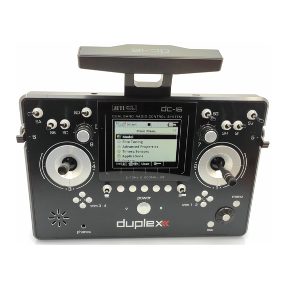
- Page 1 computer radio control system DC-16 FW 1.06...
-
Page 2: Table Of Contents
computer radio control system Inhaltsverzeichnis 1. Einleitung ....................11 4.3.5. Änderung des Steuermodus ..........19 4.3.6. Knüppelschalter/-tastermontage........20 1.1 Eigenschaften..................11 4.4. Schalter auswechseln ..............22 1.2 Struktur der Anleitung..............12 4.5. Trimmungen ..................23 1.3 Technische Unterstützung ............13 4.6. Der Akku .................... 24 4.6.1. - Page 3 computer radio control system 9. Hauptmenü ....................42 7. Erstmalige Inbetriebnahme .............. 28 9.1. Modell ....................43 7.1. Der Hauptbildschirm ..............28 9.1.1 Modell auswählen ..............43 7.2. Navigation im Menü ..............29 7.2.1 Navigation ................29 9.1.2 Neues Modell anlegen ............44 9.1.3 Grundeinstellung-Flugzeug ..........
- Page 4 computer radio control system 9.2.8 V-Leitwerksmischer ............... 63 9.5. Systemfunktionen ................88 9.2.9 Delta/Elevon Mischer ............63 9.5.1 Senderkonfiguration ............88 9.2.10 Butterfly ................64 9.5.2 Reichweiten-/Servotest ............89 9.2.11 Freie Mischer ................ 66 9.5.3 Gebermonitor ................ 90 9.2.12 Drehzahlregler/Gyro ............69 9.5.4 Servomonitor .................
- Page 5 computer radio control system 10.2 Firmwareupdate ................98 12.8 Zumischung des Seitenruders zum Querruder ....... 106 10.3 Speichern von eigenen Akustikdateien ........99 12.9 Butterfly-Mischer ................107 10.4 Sicherung der Senderkonfiguration .......... 99 12.10 Zumischung von Höhenruder zum Seitenruder ....108 10.5 Verbindung des Senders mit einem Simulator am PC .....
- Page 6 computer radio control system...
- Page 7 computer radio control system...
- Page 8 computer radio control system...
- Page 9 computer radio control system...
- Page 10 computer radio control system...
- Page 11 computer radio control system...
-
Page 12: Einleitung
Piloten und Weltmeistern entstanden. Diese Sender von Telemetriedaten vom Modell das drahtlose System Duplex wurden mit dem Ziel maximaler Anwenderfreundlichkeit, einfacher 2,4GHz, welches ebenfalls von der Firma JETI model entwickelt Bedienung, maximaler Lebensdauer und Zuverlässigkeit der worden ist. Das Übertragungssystem Duplex 2,4GHz ist sehr mechanischen Bauteile entwickelt. -
Page 13: Struktur Der Anleitung
computer radio control system Integrierte Antenne - die Antenne ist ein integraler Bestandteil des 1.2 Struktur der Anleitung Senders und somit wirksam gegen mechanische Beschädigung Zur besseren Orientierung ist die Bedienungsanleitung des Senders geschützt. DC-16 in einzelne Abschnitte aufgeteilt. Hohe Speicherkapazität - ausreichend dimensioniertes internes Allgemeine Informationen über den Sender und Unterstützung Speichervolumen zum Ablegen von Modellen, Sounds, dieses Produkts. -
Page 14: Technische Unterstützung
Fällen Ihre Fragen beantworten. Händler, Hersteller Antworten auf Ihre Fragen erhalten Sie auch bei Händlern, in Service- Zentren oder direkt beim Hersteller JETI model s.r.o. Service Auf das Produkt wird eine Garantie von 24 Monaten nach Verkauf unter der Voraussetzung gewährt, dass es in Übereinstimmung mit dieser Anleitung bei vorgeschriebener Spannung betrieben worden ist und mechanisch nicht beschädigt ist. -
Page 15: Optionales Zubehör (Nicht Im Lieferumfang Enthalten)
computer radio control system 3 Technische Daten 2.2. Optionales Zubehör (nicht im Lieferumfang enthalten) • Haltebügel aus Metall Frequenz 2,4GHz • Senderpult Abmessungen (mit Antenne) 180x270x40, • Kreuzgurt Höhe x Breite x Tiefe (230x270x40) • Ersatzschalter Gewicht 1,5Kg • Knüppelschalter / Knüppeltaster Kanalanzahl •... -
Page 16: Beschreibung Des Senders
computer radio control system 4 Beschreibung des Senders 4.1. Funktionselemente Rechtes Knüppelaggregat K1/2 – der Sender unterstützt die Einstellung eines beliebigen Modes, siehe Kapitel Kreuzknüppel -> Modeänderung. Linkes Knüppelaggregat K3/4 - der Sender unterstützt die Einstellung eines beliebigen Modes, siehe Kapitel Kreuzknüppel -> Modeänderung. Ein Schaltersatz Sa, Sb, Sc, Sd, Se, Sf, Sg, Sh, Si, Sj mit der Möglichkeit einer eigenen Konfiguration Digitaltrimmungen des linken Kreuzknüppels T3, T4... -
Page 17: Innenlayout
computer radio control system 4.2. Innenlayout Akkuanschluss Akku Anschluss PPM Out Speicherkartenadapter + Speicherkarte (2GB) Knüppelaggregat – Gas Knüppelaggregat... -
Page 18: Kreuzknüppel
computer radio control system Sichern Sie den Oberteil gegen den Unterteil durch 4.3 Kreuzknüppel gegensinniges Drehen (Kontern). Hinweis: Schalten Sie bei Arbeiten am DC-16 ohne hintere Falls Sie einen Steuerknüppel mit Schalter/Taster Warnung: Abdeckung den Sender aus und klemmen Sie den haben, sollten Sie vor einer Längenverstellung die Akku ab (ziehen Sie den Stecker). -
Page 19: Einstellung Der Federkraft Der Rückstellfeder
computer radio control system L ö s e n S i e b e i d e B e f e s t i g u n g s s c h r a u b e n d e s Verstellwiderstand bei Bewegung des Knüppelaggregates Kreuzknüppels in dieser Achse. -
Page 20: Änderung Des Steuermodus
computer radio control system 4.3.5. Änderung des Steuermodus Bei Änderung des Modes 1 auf Mode 2 oder des Modes 3 auf Mode 4 muss der arretierte Kanal von rechts nach links oder umgekehrt verlegt werden. Die Änderung kann durch Austausch beider Kreuzknüppel untereinander erzielt werden. -
Page 21: Knüppelschalter/-Tastermontage
computer radio control system 4.3.6. Knüppelschalter/-tastermontage X Y S Wollen Sie einen Sender DC-16 mit einem Schalter/Taster im Steuerknüppel verwenden, können Sie das angebotene optionale Zubehör nutzen: • Steuerknüppel mit 2-Stufenschalter • Steuerknüppel mit 3-Stufenschalter • Steuerknüppel mit Taster Ziehen Sie die Befestigungsschrauben beider Kreuzknüppel Für die Montage des Schalters/Tasters in die Kreuz- Hinweis: wieder fest. - Page 22 computer radio control system Ziehen Sie das Knüppelaggregat heraus (von der Führen Sie die Kabel durch die gleiche Öffnung, wie die Kabel Senderrückseite her). Die nachfolgende Montage geschieht d e r H a l l s e n s o r e n ( d u r c h d i e A c h s e d e r außerhalb des Senders.
-
Page 23: Schalter Auswechseln
computer radio control system der Sendermitte zu liegen kommt (3 Stecker X, Y, S aus einem Schalter auswechseln Knüppelaggregat). Sichern Sie die Kabel der Kreuzknüppel-Einheiten wieder in den Alle Schalter am Sender können leicht demontiert und durch andere Halterungen. Typen ersetzt werden. Der Sender DC-16 erkennt automatisch den Schließen Sie den Akkustecker an. -
Page 24: Trimmungen
computer radio control system Schaltertausch: 4.5 Trimmungen Schalten Sie den Sender ab und lösen Sie die Schrauben der Mit den Kreuzknüppeln steuern Sie die Basisfunktionen, wie z. B. hinteren Abdeckung. Ziehen Sie den Akkustecker ab. G as, Querruder, Höhen- und Seitenruder. Unter den Lösen Sie mit dem passenden Ziermutternschlüssel (nicht im Kreuzsteuerknüppeln befinden sich vier Tasten, die die Aufgabe der Lieferumfang des Senders enthalten) die Ziermuttern und... -
Page 25: Der Akku
computer radio control system • Die Schritt- und Wegeinstellung der Trimmung erfolgt im Der Akku ist fast voll geladen – die rote LED leuchtet stetig, die grüne LED leuchtet nicht. HAUPTMENÜ -> Feineinstellungen -> Digitaltrimmung • Der Akku ist voll geladen – die rote und grüne LED leuchten stetig. -
Page 26: Ppm-Out Anschlussbuchse
computer radio control system 4.8. Handhabung Hinweis: Betreiben Sie den DC-16 ausschließlich mit Originalakkus oder mit vom Hersteller genehmigten Den Sender DC-16 kann man bequem handhaben, wenn er an der Akkus. Antennenkonsole, wie im Bild gezeigt, festgehalten wird. 4.7. PPM-Out Anschlussbuchse Con. -
Page 27: Drahtlose Modi
computer radio control system Sendemodul-Empfängerkombination als Redundanzsystem. 5 Drahtlose Modi • Modus 3 „Schüler” bzw. „Trainer” – Das sekundäre Sendemodul ist für die Kommunikation mit dem Lehrer/Schüler- Um höchste Zuverlässigkeit und Übertragungssicherheit Sender vorgesehen. Mit dem Modell wird immer nur über den sicherzustellen ist die DC-16 mit zwei unabhängigen DUPLEX 2,4 Lehrersender und dessen primäres Sedemodul kommuniziert. -
Page 28: Einschalten Und Ausschalten Des Dc-16
computer radio control system 6 Einschalten und Ausschalten des DC-16 6.2. Ausschalten des Senders Der Sender wird durch Drücken der Taste „Power“ abgeschaltet. Vor 6.1. Einschalten des Senders dem Ausschalten werden Sie immer nach einer Bestätigung gefragt. In Ausnahmefällen kann man den Sender ohne Bestätigung durch Der Sender wird durch längeres Drücken der Taste „Power“... -
Page 29: Erstmalige Inbetriebnahme
computer radio control system Der größte Teil des Bildschirms steht als Arbeitsfläche für den 7 Erstmalige Inbetriebnahme Anwender zur Verfügung. Es ist der Bereich für die graphische Schalten Sie den Sender ein, indem Sie die Taste „Power“ lang Datendarstellung, Sie können darin telemetrische Informationen drücken und danach mit der Taste „F5(Ja)“... -
Page 30: Navigation Im Menü
computer radio control system einen Menüpunkt. Clr – Nullstellung der Stoppuhren Die Funktionstasten („Softkeys“) unterhalb des Display Stop/Start – Beginn und Ende des Fluges, Timer-Auslöser, „F1–F5“, werden je nach gewähltem Menü mit der jeweiligen Telemetrieaufzeichnung Funktion in der unteren Bildschirmzeile beschriftet. Vom Hauptbildschirm gelangen Sie ins Hauptmenü... -
Page 31: Erstellung Eines Modells - Der Assistent
computer radio control system Grundsätzlich muss ein Modell zuerst programmiert werden und als 7.3 Erstellung eines Modells – der Assistent letzten Schritt Ihr Sender mit jenem Empfänger gebunden werden, mit dem Sie dieses Modell betreiben wollen, siehe Kapitel In diesem Abschnitt werden wir Sie bei der Erstellung eines neuen Empfänger ->... - Page 32 computer radio control system D a r a u f h i n w ä h l e n w i r d e n Es erscheint ein Hinweis, ob Sie wirklich Tragflächentyp. Da wir 2 Querruderservos ein neues Modell erzeugen möchten. Mit haben, stellen wir den Parameter Taste „F5(Ja)”...
-
Page 33: Hubschrauber
computer radio control system 7.3.2 Hubschrauber Im Einführungsbildschirm drücken Sie Der Begleiter führt Sie durch die Erstellung eines einfachen Modell- die Taste „menu“. Hubschraubers. Der Hubschrauber wird über eine Taumelscheibe W ä h l e n S i e d i e P o s i t i o n gesteuert, die von drei Servos mit einer Orientierung von 120°... - Page 34 computer radio control system Im Menü „Grundeinstellungen“ wird bei der Erstellung des Schalten Sie den Sender ein. Im Hubschraubermodells, die verwendete Taumelscheibe definiert. In Hauptbildschirm drücken Sie die Taste der Anleitung des Hubschraubers finden Sie die erforderlichen „menu“. Informationen für die Konfiguration der Taumelscheibe. Die Wählen Sie den Parameter „Modellwahl/- Auswahl in diesem Menü...
- Page 35 computer radio control system Das Menü „Taumelscheibenmischer“ ist Der Sender ist an den Empfänger angebunden und an die Stromversorgung angeschlossen. In der letzten Phase führen wir ein die Konfiguration der Ausschläge der Nachjustieren der Konfiguration der Servo-Ausgangsfunktionen e i n z e l n e n S t e u e r f u n k t i o n e n d e s Hubschraubers, die in gemischter Form auf durch, siehe Kapitel 7.3.4 Einstellung der Empfängerausgänge.
-
Page 36: Schiffsmodell
computer radio control system 7.3.3 Schiffsmodell Schalten Sie den Sender ein. Im Hauptbildschirm drücken Sie die Taste Der Sender ist auch mit einem Begleiter zur Erstellung von anderen „menu“. Modelltypen als Flug- oder Hubschraubermodellen ausgestattet. Im Wählen Sie den Parameter „Modellwahl/- der Modelltypauswahl „Truck&Boat“... - Page 37 computer radio control system Wir ändern die Einstellung „Motortyp“ auf Es wird ein Hinweis angezeigt, ob Sie „vorwärts/rückwärts“ und bestätigen mit wirklich ein neues Modell erstellen wollen. der Taste „F5(>>)”. Bestätigen Sie mit der Taste „F5(Ja)”. Mit der Taste „F3(+)” erzeugen wir schrittweise alle Funktionen und ordnen die Geber des Senders zu.
-
Page 38: Einstellung Der Empfängerausgänge
computer radio control system Mit der Taste „F2(+)“ erstellen Sie einen „Wegumkehr“ - Umkehr des Ausschlags freien Mischer. Im Parameter Von: – Wir bewegen die Proportionalgeber und verfolgen, in welche Mischereingang, wählen Sie „Motor“, und Richtung die Servos ausschlagen. Wenn ein Servo in die falsche im Parameter „Zu:“... -
Page 39: Duplex Empfänger / Allgemein
computer radio control system EXT – Eingang für Telemetriesensoren. Wenn Sie mehr als nur 8 Duplex Empfänger / allgemein einen Telemetriesensor anschließen benötigen Sie den JETI EXPANDER E4. 8.1. Empfänger Beschreibung A1/A2 – Empfängerantennen. Verlegen Sie die aktiven Antennenlängen wenn möglich immer im Winkel von 90°... -
Page 40: Reichweitentest
computer radio control system Vorgehensweise: 8.5. Fail safe Schalten Sie den Sender und Empfänger aus. Alle Empfänger des Duplex 2,4GHz-Systems verfügen über die Stecken Sie den Bindestecker „BIND PLUG“ in den Funktion „fail safe“, die auf Verbindungsunterbrechungen reagiert. Empfängereingang EXT. Ab dem Zeitpunkt, wo für den Empfänger aus irgendeinem Grund Schalten Sie zuerst den Empfänger ein. -
Page 41: Fail Safe
computer radio control system >Jetibox“ und fahren Sie lt. Abbildung fort. Die Navigation erfolgt mit den Funktionstasten F1-F4. Im Menü „Out Pin Set → Set Output Pin“ wählen Sie mit den Tasten links/rechts jenen Empfängerausgang, den Sie konfigurieren möchten und fahren mit der Taste nach unten fort. Im Menü... -
Page 42: Technische Daten
computer radio control system 8.6. Technische Daten Empfänger * xternal ower onnector R11 EPC* R12 EPC* R14* R18* Rsat2 (R4Cmini) (R6 EPC*) indoor (R8 EPC*) (RMK2) Bezeichnung indoor) indoor) indoor 35x 20x7 30x23x13 44x20x7 45x24x12 38x20x6 44x20x7 50x30x12 51x24x11 50x28x13 51x24x11 50x28x13 62x38x16 62x38x16 35x23x6 Abmessungen[mm] 8 (7) 5,2 (4,8) -
Page 43: Hauptmenü
computer radio control system 9 Hauptmenü Die Zahlen auf der linken Seite geben die Reihenfolge der In das Hauptmenü gelangen Sie vom Hauptbildschirm durch Positionen im Menü an. Drücken der Taste „menu“. Das Hauptmenü setzt sich aus zwei Sektionen zusammen, der Basis- und der Anwendersektion. -
Page 44: Modell
computer radio control system Modell auswählen 9.1. Modellauswahl Wählen Sie in der Liste das gewünschte Modell aus und bestätigen Sie durch Drücken der „3D-Taste“ oder der Taste „F1(Ok)”. Der Das Menü „Modellwahl/-modifikation“ enthält alle zur Modellwechsel muss nach Aufforderung bestätigt werden. Bearbeitung des Modells notwendigen Basisfunktionen wie: •... -
Page 45: Neues Modell Anlegen
computer radio control system Ratschlag: Ratschlag1: Wenn Sie eine Änderung in der Einstellung eines Es ist ratsam, oft benutzte Modelle an den Anfang des Verzeichnisses zu legen, damit Sie bei der Auswahl bestehenden Modells durchführen legen Sie zur Sicherheit eine Sicherheitskopie ab. Das kann Ihnen d e r M o d e l l e n i c h t d a s g a n z e Ve r z e i c h n i s h e l f e n , we n n S i e z u d e n u r s p r ü... -
Page 46: Grundeinstellung-Flugzeug
computer radio control system Mit der Taste „F5(>>)” wechseln Sie zum nächsten Schritt des Menüassistenten „Grundeinstellungen“, aber nur dann, wenn zuvor der Modellname eingegeben und der Modelltyp ausgewählt wurden. 9.1.3 Grundeinstellung-Flugzeug Dieser Menüpunkt beinhaltet die Konfigurationseinstellungen der Tragflächen, Leitwerke, des Antriebs (Anzahl der Motoren), Modellname Bremsklappen und Fahrwerkservos. -
Page 47: Grundeinstellung-Heli
computer radio control system Tragfläche Antrieb(e): Anzahl der Motoren im Modell, sie kann von 0-4 gewählt werden. Je Der S ender bietet folgende S er vo -, Querruder- und nach eingestellter Anzahl werden Ausgänge für die Ansteuerung Klappenkonfigurationen an: der Motoren generiert und dem/den Gebern am Sender Bezeichnung Beschreibung zugeordnet. - Page 48 computer radio control system Anordnung der Taumelscheibe Winkel der Taumelscheibe Geben Sie den Typ der Taumelscheibe ein, den Ihr Hubschrauber Diese Parameter „Winkel“ ist nur bei der Taumelscheiben-Variante verwendet. Nähere Informationen finden Sie im Handbuch Ihres „3 servos (Std, 120°)“ erreichbar. Der Winkel, den die Punkte der Hubschraubers.
-
Page 49: Taumelscheibenmischer
computer radio control system Motortyp 9.1.5 Taumelscheibenmischer Drehen alle Motoren im Modell in einer Richtung, oder können sie in Sehr feines nachjustieren der Taumelscheiben-Servos. Hier können beiden Richtungen drehen („vorwärts/rückwärts“)? Sie die Ausschlaggrößen der einzelnen Heli-Steuerfunktionen definieren. 9.1.7 Funktions+Geberzuordnung Auf der Basis der getroffenen Konfiguration werden alle (Flug-) funktionen den Gebern am Sender zugeordnet. - Page 50 computer radio control system Zuordnung des Gebers zur Steuerfunktion der Zusatztrimmung keinen Einfluss auf die Steuerfunktion haben, bei 100% wird der Geber der Zusatztrimmung die gesamte Durch Änderungen in der Spalte „Geber“ können Sie einen Steuerfunktion in vollem Umfang beeinflussen. beliebigen Geber des Senders einer Steuerfunktion zuordnen.
-
Page 51: Servozuordnung
computer radio control system 9.1.8 Servozuordnung Der Assistent fragt Sie nach der Bestätigung zur Erstellung des Modells „Modell aktivieren?“. Wenn Sie zur Bestätigung mit der Am Bildschirm wird die Zuordnung von den Senderfunktionen zu Taste „F1(Nein)” , antworten, kehren Sie zum Assistenten zurück den Empfängerkanälen angezeigt. - Page 52 computer radio control system Darstellung des Servoausschlags Hinweis: Die Größe des Maximalausschlages können Sie Im oberen Teil des Menüs ist der aktuelle Ausschlag für den weiterhin durch die Trimmeinstellung, durch ausgewählten Kanal dargestellt. Alle Änderungen in diesem Menü vergrößerte Ausschläge (Mischer!) und weitere werden unmittelbar wirksam.
-
Page 53: Feineinstellungen
computer radio control system den klassischen oder 3D-Flug ausgesprochen hilfreich. Jede der 9.2. Feineinstellungen beschriebenen Flugzustände erfordert unterschiedliche - erweiterte Einstellmöglichkeiten für Modelle.. Einstellungen, um jederzeit eine einfache und präzise Steuerung zu • gewährleisten. Alle derartigen Anpassungen können sehr einfach Flugphasen mittels unterschiedlicher Flugphasen definiert werden. - Page 54 computer radio control system sein. Durch das Umschalten in eine andere Flugphase nimmt der Hinzufügen einer Flugphase Parameter die eingestellten Werte für die jeweilige aktiven Mit der Taste „F3(+)” fügen Sie eine neue Flugphase hinzu. Falls Sie Flugphase an. diese als Kopie einer bereits bestehenden erstellen wollen, markieren Sie die zu kopierende Flugphase und drücken die Taste •...
- Page 55 computer radio control system • Verzögerung eine Flugphase Häkchen - die Aktivierungsbedingung ist erfüllt, Diese Verzögerung definiert die Umschaltzeit von der aktiven • Kreuz - die Aktivierungsbedingung ist nicht erfüllt. Flugphase in die Nächste. Eine Umschaltung beinhaltet oftmals In der Statuszeile wird die aktuelle Flugphase angezeigt. g r u n d s ä...
-
Page 56: Digitaltrimmung
computer radio control system Standardflugphase festlegen 9.2.2 Digitaltrimmung Die Trimmung der Haupt-Steuerfunktionen erfolgt über vier Tasten, Eine ausgewählte Flugphase können Sie als Standard-Flugphase die unterhalb der Knüppelaggregate angeordnet sind. definieren. Nach Auswahl der gewünschte Flugphase betätigen Sie Definition der Schrittweite und auch des gesamten Trimmweges „F4(Opt.)”... -
Page 57: Flugphasentrimmung
computer radio control system Trimmbereich Gültigkeitsbereich Wenn Sie die Spalte mit der Bezeichnung „Weg“ editieren, Die Servoausschläge können für alle Flugphasen gültig sein – bestimmen Sie die möglichen gesamten Trimmwege in beide Erdkugel-Symbol und der Buchstabe G. Jede Flugphase kann ihre Steuerrichtungen eigene Definition der Servoausschläge haben –... -
Page 58: Dual Rate/Expo
computer radio control system 9.2.4 Dual Rate/Expo Durch Markieren einer der Steuerfunktionen mit dem Cursor und Betätigen von „F4(edit)” oder der „3D-Taste“ gelangen Sie in den Wollen Sie mit einem Geber des Senders, z.B. einem Schalter die Editiermodus dieser Parameter, in das Menü „Dual-Rate/Expo Ruderwege oder den Verlauf der Steuerfunktion beeinflussen, bearbeiten“... -
Page 59: Funktionskurven
computer radio control system Gültigkeitsbereich Wert verringern sich die Ausschläge. Diese Einstellungen können für alle Flugphasen gültig sein – Einen exponentiellen Verlauf erzeugen Sie über den Parameter „Erdkugel-Symbol“ und der „Buchstabe G“. Jede Flugphase kann „Exponential“ . Wenn dieser Parameter gleich Null ist, verhält auch ihre eigene D ualR ate/Expo -D efinition haben –... - Page 60 computer radio control system Einstellung der Funktionskurven Steuerfunktion Wenn Sie die Kurve einer der Steuerfunktionen einstellen möchten, Kurven / Verläufe der Steuerfunktion editieren Sie die Spalte „Kurve“, oder markieren mit dem Cursor die Verzögerung bei positiver und negativer Veränderung der Steuerfunktion.
- Page 61 computer radio control system Erzeugen Sie eine eigene Kurve durch Verändern der Positionen Standard Linearer Verlauf, entlang der senkrechten Achse einzelner Punkte. Jeder Punkt kann vertikal und horizontal bewegt verschiebbar werden. Durch Drehen der „3D-Taste“ oder mit den Tasten „F3“ konstant Ein vorgegebener, einstellbarer Wert für das und „F4“...
-
Page 62: Querruderdifferenzierung
computer radio control system 9.2.6 Querruderdifferenzierung Differenzierung Jede Querruder–Steuerrichtung kann einen unterschiedlichen Um eine Rollbewegung des Modells exakt um die Rumpf- Steuerweg eingestellt haben. Die mit „pos.“ und „neg.“ Längsachse durchzuführen und unerwünschte Gierbewegungen zu bezeichneten Zeilen enthalten pro verwendetem Servo eine Spalte unterdrücken müssen i.A. -
Page 63: Ailevator
computer radio control system 9.2.7 Ailevator Ruderwege des Ailevator Für die gemischten Steuerfunktionen können unterschiedliche Die Höhenrudersteuerung ist auf zwei Servos aufgeteilt, wobei die rechte und linke Seite unabhängig voneinander angesteuert Steuerwege eingestellt werden. Die mit „Höhe“ und „Querruder“ werden. Durch die Funktion „Ailevator“ wird ein Zusammenwirken bezeichneten Zeilen enthalten zwei Spalten S1 und S2, welche die zwischen der Querruder- und Höhenruderfunktion erreicht. -
Page 64: V-Leitwerksmischer
computer radio control system 9.2.8 V-Leitwerksmischer Taste“ wechseln Sie zum Editiermodus der einzelnen Servos. Mit der Taste „F1(Sym.)” schalten Sie beim Editieren die aktuelle Änderung Ist das Modell mit einem V-Leitwerk ausgestattet benötigt es einen aller Parameter der Zeile ein oder aus. entsprechenden Mischer zur Realisierung der Seiten- und Höhenruderfunktion. -
Page 65: Butterfly
computer radio control system Aktivierung der aerodynamischen Bremse Ruderwege des Höhenruders und der Querruder Unter der mit „Geber“ bezeichneten Position des Menüs ordnen Sie Einzelne Steuerfunktionen können verschiedene Wege haben. Die den Geber zu, mit dem Sie die Bremse aktivieren. Ob die mit „Höhe“... - Page 66 computer radio control system Aktuelle Wegeinstellungen der "Luftbremsen". Diese Werte sind v o n d e n ( n a c h f o l g e n d b e s c h r i e b e n e n ) g e w ä h l t e n B u t t e r f l y - Fe i n e i n s t e l l u n g e n abhängig.
-
Page 67: Freie Mischer
computer radio control system 9.2.11 Freie Mischer Erzeugen eines freien Mischers Wenn Sie eine gegenseitige Beeinflussung einiger der Mit der Taste „F2(+)” erzeugen Sie einen neuen Mischer. Nach dem Drücken der Taste erscheint das Konfigurationsmenü für die Steuerfunktionen wünschen erzielen Sie dies auf einfache Weise mit Grundparameter des Mischers. - Page 68 computer radio control system Verzögerung der Reaktion der Ausgangsfunktion bei positiver / negativer Veränderung Das Ansprechen des Servos auf den Geber des Senders wird in der Zeit aufgefächert, die im Parameter „Basis“ definiert ist. Die positive Verzögerungszeit ist als Zeit definiert, in welcher die Funktion von 100% bis -100% abläuft, die negative, in welcher die Funktion von - 100% bis 100% abläuft.
- Page 69 computer radio control system Einseitige/Asymmetrische Beimischung Beeinflussung der Ausgangsfunktion des freien Mixers durch die Trimmung Wenn die Steuerfunktion aus mehreren Ausgängen (Servos) gebildet wird, haben Sie die Möglichkeit einzustellen, ob der Mit dem Parameter „Trim“ des freien Mischers aktivieren / Mischer zu den Ausgängen (Servos) addiert oder subtrahiert wird, deaktivieren Sie die Beeinflussung der Ausgangsfunktion durch die d.h.
-
Page 70: Drehzahlregler/Gyro
computer radio control system 9.2.12 Drehzahlregler/Gyro den Parametern „Position 1“, „Position 2“ und „Position 3“. Durch Einstellen des/der Parameter „Position 1/2/3“ stellen Sie die Zur Stabilisierung eines Modellhubschraubers um die Hochachse jeweilige Empfindlichkeit des Kreisels in den einzelnen wird ein Kreiselsystem eingesetzt. Dessen Empfindlichkeit auf Schalterstellungen ein. -
Page 71: Gaslimiter (Heli)
computer radio control system 9.2.13 Gaslimiter (Heli) Wenn Sie mehrere Flugphasen programmiert und diesen jeweils eigene Gaskurven zugewiesen haben kann die Drehzahl im gesamten Bereich von der geringsten bis zur höchsten durch den Gaslimiter im zulässigen Bereich gehalten werden. Zur Aktivierung des Gaslimiters kann jeder beliebige Geber des Senders verwendet werden. -
Page 72: Erweiterte Einstellungen
computer radio control system Automatische Trimmung 9.3. Erweiterte Einstellungen Zuordnung eines Gebers für den Start der automatischen Trimmung. Nach dem Einschalten der automatischen Trimmung Erweiterte Einstellung der Modellsteuerung. wird die Trimmung entsprechend der aktuellen Ausschläge der Kreuzknüppel eingestellt. Je größer der Ausschlag des Kreuzknüppels ist, umso schneller stellt sich der Trimmwert in der gegebenen Richtung ein. -
Page 73: Stick/Schalter Setup
computer radio control system Entsicherung/Sicherung des Gaskanals anwenden. Die Funktion für Name und Typ des Gebers das Abstellen des Motors können Sie einem beliebigen Geber des Die ersten beiden Menüzeilen zeigen den Namen und den Typ des Senders zuordnen. Nach Aktivierung von „Motor-AUS Position“ Gebers an. -
Page 74: Drahtlosmodus/Trainer
computer radio control system • Einschalten des Senders befinden soll. Solange sich alle Geber nicht 2-Positionsumschalter - „Std. schalter” in den vordefinierten Positionen befinden wird das Modell nicht • 3-Positionsumschalter - „3-pos. schalter” aktiviert. Auf dem Senderdisplay wird das Senderlayout abgebildet, •... - Page 75 computer radio control system Modell gesendet, auch wenn die Steuerung an den Schüler Drahtloser Modus „Schüler“ übergeben wurde. Ist der Sender im „Lehrermodus“, kommuniziert sein primäres HF- Modul mit dem Modell und das Sekundäre mit dem Schülersender. Ist der Sender im Modus „Schüler“, kommuniziert sein primäres Modul mit dem Lehrersender und das Sekundäre ist inaktiv.
- Page 76 computer radio control system Schalten Sie den Schülersender ein und aktivieren Sie den Moduswahl d r a h t l o s e n M o d u s „ S c h ü l e r “. K o n f i g u r i e r e n S i e d i e Definition des Schalters für die Umschaltung der Steuerung auf Ausgangskanäle.
- Page 77 computer radio control system Schalten Sie den Schülersender (DC-16) ein und aktivieren Sie den Drahtlosmodus „Schüler“. Am Schülersender (DC-16) wechseln Sie zum Menü „Drahtlosmodus/Trainer->Student“, in welchem Sie den Ausgangskanälen die Steuerfunktionen abgestimmt auf den Lehrersender bzw. das Schulungsmodell zuweisen. Drahtloser Modus „Zwei-Weg HF“ Moduswahl Befehl zur Bindung des primären Sendermoduls mit dem Empfänger...
-
Page 78: Logische Schalter
computer radio control system In der letzten Menüzeile wird das Ergebnis des logischen Ausdrucks 9.3.4 Logische Schalter dargestellt. Im Verzeichnis der logischen Funktionen werden die Wenn Sie wünschen, dass sich einzelne oder mehrere definierten Schalter, der Operator und der Zustands der logischen Senderfunktionen auf der Basis des Zustandes mehrerer Schalter dargestellt. -
Page 79: Sprachausgabe/Ereignis
computer radio control system Emulation eines Dreistufen-Schalters Trimmung, führt zur Überblendung der jeweiligen Musik-/Sprach- /Akustiksignalausgaben. Die logische Funktion „Multi" emuliert einen 3- Stufen-Schalter. Wenn Sie zwei 2- Stufen-Schalter verwenden und durch deren Kombination einen Dreipunkt-Umschalter erstellen möchten, nutzen Sie die logische Funktion „Multi". Zuordnung des Gebers Durch Editieren des Parameters „Switch“... -
Page 80: Stoppuhren/Sensoren
computer radio control system Zurücksetzen-Timer beim Start 9.4. Stoppuhren/Sensoren Sie können jetzt wählen, welche Stoppuhren nach dem Einschalten - Einstellung der (Stopp-)Uhren und der Telemetrie des Senders oder nach Auswahl eines Modells zurückgesetzt werden. Standardmäßig werden alle Zeiten mit einem kurzen Betätigen der Löschtaste unter den Display gelöscht. - Page 81 computer radio control system • Standard - beim Timerstart wird die Zeit entsprechend der Einstellung des Start- und Zielwertes gezählt. Jedesmal, wenn der Timer durch seinen Auslöser ausgeschaltet wird, bleibt der Wert stehen. Bei wiederholtem Start setzt der Timer die Zeitmessung fort.
-
Page 82: Alarme
computer radio control system 9.4.2 Alarme Art der akustischen Signalisation Wenn Sie das JETI-Telemetriesystem nutzen, können Sie in diesem Vor dem Erreichen der Zielzeit kann eine akustische Menü die Grenzwerte (Alarmschwellen) definieren, bei deren Über- / Benachrichtigung als „Vorwarnung“ eingestellt werden. Unterschreitung Sie durch die Wiedergabe einer ausgewählten Start des Timers Sounddatei darauf aufmerksam gemacht werden. - Page 83 computer radio control system dessen Grenzwert (Alarm) Sie einstellen wollen. Aktivieren des Alarms Durch Auswahl der Abfrage „Aktiviert“ und betätigen der „3D- Taste“ stellen Sie den Alarm „scharf“ und es werden die Alarmparameter angezeigt. Definition des Grenzwertes Der Parameter „Zustand“ definiert die Bedingung, bei deren Alarme EX Erfüllung ein Alarm ausgelöst wird.
-
Page 84: Vario
computer radio control system 9.4.3 Vario zuzuordnen um den Varioton zu aktivieren/deaktivieren. Es gibt zwei Optionen der akustischen Signalisierung. Diese Parameter werden in diesem Menü angezeigt: Die Erste ist direkt durch den Sensor-Alarm gesteuert. Dies ist vor • EX Parameter: allem dann nützlich, wenn ein Nicht-EX MVario im Modell installiert Hier können Sie Ihren Sensor und seine Parameter, der als Quelle für ist. -
Page 85: Sprachausgabe
computer radio control system Die zweite Option ermöglicht es, Daten nur einmal, nach einer 9.4. 4 Sprachausgabe einzigen Betätigung des Trigger-Schalters, anzusagen. Der Trigger- Diese leistungsstarke Funktion macht es möglich, Telemetriewerte Schalter und die Telemetriewerte können selbst gewählt werden. akustisch auszugeben. Es ist nicht mehr notwendig auf das Display zu schauen. -
Page 86: Telemetrieanzeige
computer radio control system „RX-Spannung“ - Empfängerspannung 9.4.6 Telemetrieanzeige In diesem Menü können Sie die einzelnen Anzeigefenster am „Restlaufzeit“ - Zustand des Senderakkus Display konfigurieren. Wie schon in der Einleitung erwähnt wurde, ist der Hauptbildschirm das primäre Anzeigemedium des Senders. Am Bildschirm werden in aufbereiteter Form sämtliche Betriebsinformationen wie z.B. - Page 87 computer radio control system „Antenne“ - Information über die Signalstärke „Timer“ - Stoppuhren „Telem“ -Telemetriewerte der angeschlossenen Sensoren „Besitzer“ - Name des Eigentümers „Jetibox“ - Emulations-Bildschirm der JETIBOX Die Anzeigefenster können in Standard- oder doppelter Größe angezeigt werden. Bei doppelter Größe nehmen die Fenster mehr Platz am Display ein, es können dadurch allerdings mehr Informationen als zuvor oder aber auch die gleichen Werte in...
- Page 88 computer radio control system Parameter den Wert „S“ (Verzeichnissymbol)“, ist diese Konfiguration nur für die aktuelle Flugphasen gültig. In diesem Fall bewirkt eine Änderung der Flugphasen auch eine entsprechende Anpassung der Displayanzeige. Anlegen eines neuen Anzeigefensters Mit der Taste „F3(Add)” erzeugen Sie einen neues, leeres Fenster. Durch Editieren wählen Sie zuerst den Typ des Anzeigefensters.
-
Page 89: Systemfunktionen
computer radio control system Sprache 9.5. Systemfunktionen Mit diesem Menüpunkt legen Sie die Spracheinstellungen des Senders fest. Alle Texte und Sprachausgaben basieren auf dieser Konfiguration der Systemfunktionen des Senders. Alle Einstellung. Einstellungen in diesem Menü sind global – unabhänging von der Modellwahl. -
Page 90: Reichweiten-/Servotest
computer radio control system Anlage neuer Modelle und der Telemetrieaufzeichnung Es können nur jene Ausgangskanäle getestet werden, die eine berücksichtigt. Ausgangsfunktion in der Modellkonfiguration zugeordnet haben, einzelne Servos können durch Betätigen der „3D-Taste“ vom Test Distanzeinheit: ausgenommen werden. Dieser Parameter legt die verwendete Maßeinheit fest - Meter bzw. Fuß. -
Page 91: Gebermonitor
computer radio control system testen möchten. • Beim maximalen (mechanischen) Ausschlag des Auslösen des Servotesters Proportionalgebers erreicht der ausgewertete Ausschlag nicht den maximalen Bereich der Anzeige. Mit der Taste „F3(Start)” starten Sie den Servotester auf den aktiven Ausgängen. Der Servotester läuft stetig weiter, auch wenn Sie dieses Menü... -
Page 92: Servomonitor
computer radio control system 9.5.4 Servomonitor In diesem Menü wird der Status der einzelnen Empfängerausgänge dargestellt. Anhand der Balken können Sie die einzelnen „Steuersignale“ erkennen, die der Empfänger an die Servos weitergibt woraufhin diese die entsprechende Stellung anlaufen. Dieses Menü können Sie auch über die Funktionstaste im Konfigurationsmenü... -
Page 93: System Sounds
computer radio control system 9.5.5 System sounds • Stoppschalter Player - nach Aktivierung des zugeordneten Schalter werden alle aktuell abgespielten WAV-Dateien gestoppt. In diesem Menü können Sie Systemereignissen einen beliebigen Dies hat keinen Einfluss auf jede weitere Wiedergabe. Sound/Klang aus dem Verzeichnis /Audio/ zuordnen. 9.5.6 Lautstärke 9.5.7 Audio Player In diesem Menü... -
Page 94: Jetibox
computer radio control system sie nicht mit „F3()“ beendet wird – ebenso wird die Wiedergabe 9.5.8 JETIBOX auch nach Verlassen dieses Menüs fortgeführt. Aus Gründen der maximalen Kompatibilität mit dem DUPLEX System der I. Generation ist der Sender mit einer Emulationsfunktion der JETIBOX ausgestattet. -
Page 95: Usb
computer radio control system 9.5. Wenn Sie eine Kommunikation zwischen dem PC und dem Sender aufnehmen wollen, sollten Sie die USB-Einrichtung mit einem Kabel anbinden und im Sender die Verbindung aktivieren. Die Aktivierung kann folgendermaßen durchgeführt werden: Manuell – Sie wechseln zum Menü „System->USB". Beim Verlassen des Menüs deaktivieren Sie die Verbindung. -
Page 96: Die Gasverriegelung
computer radio control system 9.6 Die Gasverriegelung 9.7 Geber auswählen Die Funktion der Gasverriegelung („Motor-AUS“) ist eine In dieses Menü für die Auswahl eines Steuergebers gelangen Sie aus Sicherheitsfunktion des Senders. Ist diese Funktion aktiviert, diversen Konfigurationsmenüs, beispielsweise bei der Definition reagiert keine der Motorsteuerung zugeordnete Ausgangsfunktion von Flugphasen, Aktivierung von Dual-Rate, Exponentialfunktionen auf den Geber des „Gaskanals“. - Page 97 computer radio control system Richtungsumkehr der Auswertung Ratschlag: Überlegen Sie bereits vor der Zuordnung des Gebers, in welcher Position Sie ihn aktiv haben möchten, und Mit der Taste „F3(Rev.)” ändern Sie die Richtung der bewegen Sie den Geber während seiner Zuordnung in Geberauswertung.
-
Page 98: Menü Trim
computer radio control system 9.8 Menü Trim 9.9 Verarbeitungsverfahren und Auswertung der Ausgangsfunktionen des Senders Abbildung der Trimmwerte von Steuerfunktionen, die den Knüppelaggregaten zugeordnet sind. Ins Menü gelangen Sie durch Der Sender stellt nach genau festgelegten Geber Regeln die Ausgangsfunktionen für die Drücken der „3D-Taste“... -
Page 99: Anschluss Des Senders An Den Pc
computer radio control system Voice – Speicherbereich für „synthetische” Sprachdateien 10 Anschluss des Senders an den PC Manual – Betriebsanleitung Der Sender ist zum Datentransfer mit einem mini USB-Anschluss Hinweis: S i e h a b e n ü b e r d e n P C u n e i n g e s c h r ä n k t e ausgestattet. -
Page 100: Speichern Von Eigenen Akustikdateien
computer radio control system 10.3 Speichern von eigenen Akustikdateien (Mischer, Dual-Rate, Expo usw.) übernommen, diese Einstellungen sind in der Simulatorsoftware vorzunehmen. Wie bereits erwähnt, unterstützt der Sender die Wiedergabe von Akustik-dateien des Typs *.wav. Diese Dateien können zur Alarmsignalisierung oder auch einfach gebergesteuert – quasi „auf 10.6 Auslesen der Telemetrie Knopfdruck“... -
Page 101: Sicherheitsbestimmungen
computer radio control system 11.2 Allgemeine Informationen 11 Sicherheitsbestimmungen Seien Sie besonders vorsichtig bei etwaigen Montageeingriffen am Sender 11.1 Der Akku und beachten Sie bei Arbeiten an den Laden Sie den Akku grundsätzlich im Sender mit dem e l e k t r o n i s c h e n K o m p o n e n t e n d i e mitgelieferten Adapter allgemein gültigen Regeln für den Umgang... - Page 102 computer radio control system Vermeiden Sie die Manipulation mit Magneten oder die Einwirkung von starken Magnetfeldern in der Nähe des Senders. Halten Sie alle beweglichen mechanischen Teile sauber. Schirmen Sie die Antennen nicht mit Metallgegenständen oder Körperteilen ab. Dies könnte zum Reichweitenverlusten des Senders führen.
-
Page 103: Spezifische Mischer - Flugzeug
computer radio control system 12 Spezifische Mischer – FLUGZEUG 12.2 Q uerruderdifferenzierung D i e s e Fu n k t i o n b e f i n d e t s i c h b e i z u v o r g e w ä h l t e r 12.1 A erodynamische Bremsen Tragflächenkonfiguration mit zwei oder mehreren Querrudern im Menü... -
Page 104: Ailevator
computer radio control system 12.3 Ailevator 12.4 V -Leitwerk Die Funktion der gekoppelten Steuerung von Höhen- und Die Funktion der gekoppelten Steuerung von Höhenruders und Q u e r r u d e r b e f i n d e t s i c h b e i z u v o r g e w ä h l t e r S e i t e n r u d e r s b e f i n d e t s i c h b e i z u v o r g e w ä... -
Page 105: Mischer Delta/Elevon Für Nurflügel Und Deltas
computer radio control system 12.5 Mischer Delta/Elevon für Nurflügel und Deltas 12.6 Beimischung aerodynamischer Störklappen zum Höhenruder. Die Funktion der gekoppelten Steuerung von Quer- und H ö h e n r u d e r b e f i n d e t s i c h b e i z u v o r g e w ä h l t e r Ist die Tragfläche des Modells mit Störklappen versehen, verwendet Leitwerkskonfiguration „Kein LW (Delta/Elevon)“... -
Page 106: Beimischung Der Querruder Zum
computer radio control system Markieren Sie diesen soeben erzeugten 12.7 Beimischung der Querruder zum Seitenruder Mischer in der Liste und wechseln mit der Taste „F4(edit)“ zur er weiter ten Eine gekoppelte Quer- und Seitenruderfunktion verbessert bei Einstellung, siehe Kapitel „Freie Mischer“. manchen Modelltypen, zB. -
Page 107: Zumischung Des Seitenruders Zum Querruder
computer radio control system Markieren Sie diesen soeben erzeugten 12.8 Zumischung des Seitenruders zum Querruder Mischer in der Liste und wechseln mit der Taste „F4(edit)“ zur er weiter ten Eine gekoppelte Seiten- und Querrruderfunktion verbessert bei Einstellung, siehe Kapitel „Freie Mischer“. manchen Modelltypen den Kurvenflug indem dadurch ev. -
Page 108: Butterfly-Mischer
computer radio control system 12.9 Butterfly-Mischer Markieren Sie diesen soeben erzeugten Mischer in der Liste und wechseln mit der Die sogenannte Butterfly-Stellung ergibt eine sehr effektive Ta s t e „ F 4 ( e d i t ) “ z u r e r we i t e r t e n aerodynamische Bremse für Segelflugmodelle. -
Page 109: Zumischung Von Höhenruder Zum Seitenruder
computer radio control system 12.10 Zumischung von Höhenruder zum Seitenruder Markieren Sie diesen soeben erzeugten Mischer in der Liste und wechseln mit der Mit dieser Beimischung kann ein auftretendes Nickmoment bei der Ta s t e „ F 4 ( e d i t ) “ z u r e r we i t e r t e n Seitenruderbetätigung kompensiert werden. -
Page 110: Zumischung Von Wölbklappen Zu Querrudern
computer radio control system 12.11 Zumischung von Wölbklappen zu Querrudern Markieren Sie diesen soeben erzeugten Mischer in der Liste und wechseln mit der Ist die Tragfläche des Modells mit Querrudern und mindestens zwei Ta s t e „ F 4 ( e d i t ) “ z u r e r we i t e r t e n (Wölb-) Klappen ausgerüstet kann dieser Mischer zur Erhöhung der Einstellung, siehe Kapitel „Freie Mischer“. -
Page 111: Zumischung Von Bremsklappen Zu Den Querrudern
computer radio control system 12.12 Zumischung von Bremsklappen zu den 12.13 Zumischung von den Wölbklappen zum Querrudern Höhenruder Ist die Tragfläche des Modells mit Querrudern und mindestens zwei Ist die Tragfläche des Modells mit Querrudern und mindestens vier Klappen ausgerüstet kann dieser Mischer zur Erhöhung der Klappen ausgerüstet, kann dieser Mischer zur Erhöhung der Querruder-Wirksamkeit genutzt werden. -
Page 112: Wölbklappenmischer - Steuerung Der Lwölbung
computer radio control system Markieren Sie diesen soeben erzeugten 12.14 Wölbklappenmischer - Steuerung der Mischer in der Liste und wechseln mit der Profilwölbung Ta s t e „ F 4 ( e d i t ) “ z u r e r w e i t e r t e n Einstellung, siehe Kapitel „Freie Mischer“. -
Page 113: Abstellen Des Motors
computer radio control system 12.15 Abstellen des Motors 12.16 Leerlaufeinstellung des Motors Diese Funktion gewährleistet ein sicheres Abstellen von Mit dieser Funktion wird der Leerlauf-/Standgasstellung Verbrennungsmotoren über das Gasservo/Zündung oder auch eine eingestellt/angehoben, die Konfiguration erfolgt im Menü Sicherung/Entsicherung von Elektromodellen bzw. deren „Erweiterte Einstellungen->Spezielle Modelloptionen“. - Page 114 Bruckmann Gernot Ciniburk Tomáš Hacker Rainer Hofmaier Wolfgang Hubáček Zdeněk Janáček Bedřich Lichtblau Leo Materna Milan Mojzes Lubomír Neesen Uwe Pastyřík Miroslav Pfeiffer Manfred Pop František Rummer Marcus Škorpil Štěpán Šteigl Matěj Šteigl Zdeněk Vorel Karel JETI model Team.
- Page 115 computer radio control system...
- Page 116 computer radio control system...
- Page 117 ® JETI model s.r.o. Lomená 1530, 742 58 Příbor www.jetimodel.de...
- Page 118 computer radio control system DC-16 FW 1.06...
- Page 119 computer radio control system 4.3.4. Ratchet Tension Adjustment ..........13 1. Introduction ................... 06 4.3.5. Transmitter Mode Switch ..........14 1.1 Features .....................06 4.3.6. Transmitter Gimbals with Switch or Button Installation 1.2 Table of Contents ................07 ....................15 1.3 Technical Support ................08 4.4.
- Page 120 computer radio control system 7. Initial switching-on ................23 9. Main menu ....................35 7.1. Main display ..................23 9.1. Model ....................36 7.2. Navigation in the Menu ..............24 9.1.1 Model Selection ..............36 7.2.1 Browsing through the Menu ..........24 9.1.2 New Model ................
- Page 121 computer radio control system 9.2.7 Ailevator Function ............... 54 9.4.5 Sensors/Logging Setup ............75 9.2.8 V-Tail Mix ................. 55 9.4.6 Displayed Telemetry ............. 75 9.2.9 Delta/Elevon Mix ..............55 9.5. System ....................78 9.2.10 Butterfly Mix ................. 56 9.5.1 Configuration ................. 78 9.2.11 Free Mixes ................
- Page 122 computer radio control system 10. Transmitter to PC Connection ............87 12.3 Ailevator ..................93 12.4 V-Tail Mix ..................93 10.1 Memory & System Files ..............87 12.5 Delta/Elevon Mix ................94 10.2 Update Firmware ................87 12.6 Spoilers to Elevator Mix ............... 94 10.3 Sounds, Alarms &...
- Page 123 computer radio control system...
-
Page 124: Introduction
This by Jeti Model in the Czech Republic. This system has been reliably transmitter was created with the goals of maximum utility, simple used for many years. -
Page 125: Table Of Contents
computer radio control system Large Memory – 4GB memory space for storing models, sounds, and 1.2 Table of Contents telemetry data. To make navigation faster, the DC-16 transmitter Instruction Manual USB Connector – convenient connection to your PC. Fast firmware & has been divided into 5 basic groups: sound upgrades, telemetry data downloads. -
Page 126: Technical Support
Third party transactions are not covered by this warranty. Proof of purchase is required for warranty claims. Repair or replacement decisions are at the sole discretion of Jeti Model CZ or an authorized service provider. This warranty does not cover cosmetic damage or damage due to an accident, misuse, abuse, negligence, commercial or research use, or modification of or to any part of the product. -
Page 127: Optional Accessories (Not Included)
computer radio control system 3 System Specifications 2.2. Optional Accessories (Not Included) Frequency 2.4GHz • Transmitter Neck Strap Bracket 180x270x40 mm • Dimensions Transmitter Tray 7.1x10.6x1.6", WxLxH • 4-Point Adjustable Harness (230x270x40mm) (with Antenna) (9.1x10.6x1.6") • Neck Strap Weight 1.5Kg (53 oz) •... -
Page 128: Description Of Transmitter
computer radio control system 4 Description of Transmitter 4.1. Control Identification Right Stick 1, 2 – the DC-16 Transmitter Supports Modes 1-4, see Control Sticks -> mode change Left Stick 3, 4 the DC-16 Transmitter Supports Modes 1-4, see Control Sticks ->... -
Page 129: Assembly Identification
computer radio control system 4.2. Assembly Identification Battery Connector Transmitter Battery Pack PPM Output Connector Left Gimbal Assembly Right Gimbal Assembly... -
Page 130: Control Stick Assembly
computer radio control system If you have installed optional sticks with switch or 4.3 Control Stick Assembly Warning: button ends; make sure that while adjusting the stick length you observe the wires that pass through Note: When handling with back cover removed always the stick shaft and through the gimbal opening in switch-off the transmitter and disconnect the order to prevent damaging the connecting cables. -
Page 131: Control Stick Tension Adjustment
computer radio control system Loosen both machine screws securing the control stick decrease. By turning the screw clockwise, you will tighten assembly. spring tension. As a result the moving resistance of the control stick will increase. Adjust (rotate) to desired position. Securely tighten both machine screws securing the control stick Reconnect transmitter battery pack and reinstall radio back assembly. -
Page 132: Transmitter Mode Switch
computer radio control system 4.3.5. Transmitter Mode Switch The DC-16 transmitter allows you to switch between Mode 1, 2, 3 and 4 stick configurations with just few simple steps. In order to do some of these, the stick control assemblies will need to be swapped. Switch-off the transmitter and remove the 10 screws that secure the radio back cover. -
Page 133: Transmitter Gimbals With Switch Or Button Installation
computer radio control system 4.3.6. Transmitter Gimbals with Switch or Button X Y S Installation If you want to operate the DC-16 transmitter using the optional stick end switch or button functions, you must purchase one or more of these separately: •... - Page 134 computer radio control system Remove both machine installation screws for each of the you observe the wires that pass through the stick shaft control stick assemblies. and through the gimbal opening in order to prevent Carefully remove both control stick assemblies. Gently pull in damaging the connecting cables.
-
Page 135: Swappable And Assignable Switches
computer radio control system Connect control stick assembly wires to the Tx board connector Swappable and Assignable Switches (3 wires X, Y, S ). Pay close attention to the wire lengths. Connect the longest wire as the first one from the outside of the One of the most important features of a Jeti transmitter is the switch transmitter (3 connectors X, Y, S). -
Page 136: Digital Trims
computer radio control system Switch Exchange: Digital Trims Switch-off the transmitter and remove the 10 screws that secure Transmitter gimbals are used for controlling the basic flight the radio back cover. Next, remove the radio back cover. functions like throttle, roll(aileron), pitch(elevator), and yaw(rudder). Be sure to disconnect the transmitter battery pack Immediately under the transmitter gimbal sticks you can see four connector. -
Page 137: Transmitter Battery Pack
computer radio control system 4.6.2. Battery Replacement 4.6 Transmitter Battery Pack Should you decide to replace the transmitter battery, please follow The DC-16 transmitter is powered by a Li-Ion type battery pack and these steps: comes equipped with its own built-in advanced battery Switch-off the transmitter and remove the 10 screws that management and charging circuit. -
Page 138: Ppm Output Connector
computer radio control system 4.7. PPM Output Connector 4.8. Handling The DC-16 transmitter can be comfortably carried by holding it for The PPM output is accessible via connector labeled „B“. This the antenna cover/handle as shown on the picture. connector features the non-stabilized battery voltage output in the range of 3,2V - 4,2V (max. -
Page 139: Rf Transmitter Modules
computer radio control system In the „Student“ mode the DC-16 transmitter communicates via the 5 RF Transmitter Modules secondary RF module with the instructor’s transmitter. If you operate two of the DC-16 transmitters; one of them in the „Instructor“ mode In order to achieve the highest transmission quality and reliability of and the other one in the „Student“... -
Page 140: Transmitter Powering On/Off
computer radio control system 6 Transmitter Powering ON/OFF 6.2. Transmitter Turning-OFF The transmitter is switched-off by pressing the „Power“ main 6.1. Transmitter, Powering-ON button. Before complete power-down is achieved you will be asked for additional confirmation. In case of an emergency, a fast turn-off Switching-on is achieved by pressing and holding the „Power“... -
Page 141: Initial Switching-On
computer radio control system items or alarms, the number of available pages will automatically 7 Initial switching-on increase or decrease as needed. Turn the transmitter on by pressing and holding the „Power“ button In this example, the desktop page displays the following for a couple of seconds and then press the "F5 (Yes)"... -
Page 142: Navigation In The Menu
computer radio control system 7.2. Navigation in the Menu To navigate within the transmitter menus, use the following buttons: The „menu“ button allows you to switch between the main display and the transmitter‘s main menu. Also, If you push this button while turning the 3D Control Selector to edit values, the values can be changed faster. -
Page 143: Model Set-Up Guide
computer radio control system 7.3 Model Set-up Guide Notice: For safety reasons we recommend first removing the propeller. In this section we will guide you, step by step, through the process of Switch-on the transmitter. In the main creating a new model airplane and helicopter. Each step of the guide display push the key „menu“. - Page 144 computer radio control system This page displays the flight control Bind transmitter with the receiver, see chapter 8.4 Receiver->Binding. functions and their transmitter switch Once your transmitter has been bound with the receiver and you have assignments. Here you can verify that your re-applied power to the receiver, the last setup phase is the tuning of flight control functions are correctly assigned your servo output functions.
-
Page 145: Helicopter
computer radio control system Switch-on the transmitter. In the main Note: When setting up your spoilerons be sure that the ailerons still display push the key „menu“. Select the have enough travel to control your airplane when the spoilerons are deployed. In this menu the „(Sym) F1“ button will link or item „Model“... - Page 146 computer radio control system When you create a new helicopter model you are required to define The screen will display a question which the swash plate configuration for the model. Please refer to your asks if you really want to create and activate helicopter’s instructions and verify that you have the correct swash the new model.
-
Page 147: General
computer radio control system 7.3.3 General Switch-on the transmitter. In the main The DC-16 transmitter is not only equipped with the assistants for display push the key „menu“. Select the airplanes or helicopters, but it also has a „General“ assistant which item „Model“... - Page 148 computer radio control system The „Servo Setup“ menu is where you In the „Function Assignment“ menu can set all of your servo neutral positions, use the „F3(Add)“ button to create all of servo output throw limits, servo reversing, your desired functions. Then you can assign delay etc.
-
Page 149: Set-Up Of Receiver Outputs
computer radio control system To assign a switch for the activation and Note: You should Mechanically adjust all of your servo arms and servo deactivation of the free mixer press the linkages to be as close to neutral or center as as possible so that „F4(Edit)“... -
Page 150: Duplex Receivers
computer radio control system 8 Receiver A1/A2 - receiver antennas. The antennas should be installed so that the wires form a 90° angle relative to each other. 8.1. Description 8.2. Installation Whenever possible, you should wrap the receiver in foam and place it as far as possible from sources of interference (servos, electric motors). -
Page 151: Range Test
computer radio control system Each receiver channel can be configured to one of the modes 8.4. Range Test described above. We recommend that you setup „fail safe“ positions for every output which enables your model to stay in a stable The range test will verify that the transmitter and receiver are condition. -
Page 152: Technical Data Receivers
computer radio control system 8.6. Technical data receivers * xternal ower onnector R7plus R11 EPC* R12 EPC* R14* R18* Rsat2 Basic Data (R4C (R4L (R5L (R6 EPC*) (R6l (R8 EPC*) (RMK2) mini) indoor) indoor) indoor) indoor) indoor) 35x 20x7 30x23x13 38x20x7 44x20x7 47x20x7 45x24x12 43x24x11 44x20x7 51x24x11 50x30x12 51x24x11 50x28x13 51x24x11 50x28x13 62x38x16 62x38x16 35x23x6 Dimensions [mm] 8 (7) 4,8 (4,5) 5,2 (4,8) -
Page 153: Main Menu
computer radio control system 9 Main menu The numbers on the left side of the display shows the sequence You reach the basic menu from the main display by pressing the of the menu items. „menu“ key. The main menu is divided into a basic and a user section. In the basic menu, the menu items are divided into sub-menus. -
Page 154: Model
computer radio control system Model selection 9.1. Model In the list of models, select the required model and confirm it by pressing the „3D button“ or „F1(Ok)“ button. You will be prompted The „Model“ menu contains basic functions for working with your to confirm loading of the selected model. -
Page 155: New Model
computer radio control system 9.1.2 New Model Note: If you would like to make set-up changes in an existing Selecting this menu item starts the new model creation assistant. model, you should first make a copy of the original The assistant begins creating a new model profile as soon as you setup. -
Page 156: Basic Configuration- Airplane
computer radio control system will enter the model name that you want the transmitter to use when 9.1.3 Basic configuration- AIRPLANE the model is stored in the transmitter‘s memory. The maximum In this menu you will setup the wing configuration, tail type, available space for a model name is 12 characters, including spaces. -
Page 157: Basic Configuration - Helicopter
computer radio control system 9.1.4 Basic Configuration - HELICOPTER Tail Assembly The following tail option are available: Type Description Standard tail assembly with one horizontal control Standard 1H1V (elevator) and one vertical control (rudder) V-tail 2H Traditional V-tail Tail assembly with two elevator servos and one Ailvator 2H1V rudder servo Swash Plate Type... -
Page 158: Swash Mix
computer radio control system • „Mechanical“ - this swash plate type uses a single servo for Governor each flight function. This is the swash plate type to select if you are In some helicopter setups a governor function is used for motor using a flybarless controller. -
Page 159: Basic Configuration-General
computer radio control system 9.1.6 Basic Configuration-GENERAL Flight function Renaming By editing each „Function“ item you can rename a flight function Number of Motors in the Model from its original name to any name that you choose. This is where you select the number of motors in your model. It is Assignment of a Control Element to a Flight Function possible to select 0-4 motors. -
Page 160: Servo Assignment
computer radio control system of these items you will enter the menu: „Select control input“, see Note: The initial assignment is carried out in accordance with your chapter 9.7. The assignments can easily be verified by the graphic selected transmitter mode. If the initial assignment is incorrect found beside the control element description in the „Trim “... -
Page 161: Servo Setup
computer radio control system 9.1.9 Servo Setup Assignment of Transmitter Output Functions to Receiver This menu is for the additional tuning of output functions of the Channels transmitter->receiver channels->servos. The assignment of a Select the required receiver channel and press the „3D button“. transmitter output function to a receiver channel is shown in the Now you can choose which function you want assigned to the upper part of the menu (first item below the menu description). - Page 162 computer radio control system Advice: When building a model try to mechanically adjust the Servo Reversing neutral positions as perfectly as possible. If you are Use this item to reverse the direction of a servo’s travel. going to use a high „Center (Subtrim)“ value in order to Delay of positive/negative set-up a servo neutral, the resulting servo throw will be This item allows you to delay the servo channel‘s travel time...
-
Page 163: Fine Tuning
computer radio control system Up to 10 different flight modes are available for every single model. 9.2. Fine Tuning 9.2. Fine Tuning Each one of these flight modes can be named differently for instant - Extended program functions for fine tuning your models recognition. - Page 164 computer radio control system Naming Flight Modes Advice: If no flight mode is required, do not change the pre-set configuration. We recommend naming flight modes according to their function, for example: Take Off, Soaring, Autorotation…. Flight mode names/labels can be easily edited at any time. Flight Mode Delays The time delay function can help smooth the transition from one flight control state to another.
- Page 165 computer radio control system column to help you determinate the ON or OFF switch position for each flight mode. • Check Mark – ON Position • X Mark – OFF Position When the flight mode is activated the flight mode name can be seen the top of the desktop screen.
-
Page 166: Digital Trim
computer radio control system This is useful when you are setting up a new model from a copied Advice: For a maiden flight we recommend using larger trim model and you want different flight modes. steps. After familiarizing yourself with your model’s behavior you can switch to smaller steps for finer Advice: After you make a configuration change or perform a... -
Page 167: Dual Rate/Exponential
computer radio control system Pressing the “F1 (Sym.)” turns ON/OFF the lock which allows each output to be adjusted either together (symmetrically), or independantly. Trim Travel Global or Separate Setting The servo trim position for each function output can be set either collectively for all flight modes by selecting the “G-(globe symbol)”... - Page 168 computer radio control system Expo/Dual Rates Travel Setting Percentage of travel Every switch position can define a different function and Exponential rate setting exponential value. Any change made to the settings can be directly Assignable switch option observed on graphic interface Graphic interface Dual/Triple rate setting is defined by percentage of the travel higher number increases travel, a lower number decreases travel.
-
Page 169: Programmable Function Curves
computer radio control system 9.2.5 Programmable Function Curves and in the second mode it is disabled). There are some specific conditions where setting this option for one function has an effect in Function curves define the relationship between the actual position another function. - Page 170 computer radio control system The function curve can selected from the existing list or from custom, previously modified options. Available Options: Standard Linear values, set In/Out point Constant Constant value, set point All of the points can be moved in both horizontal and vertical directions.
-
Page 171: Aileron Differential
computer radio control system Global or Separate Function Curve Setting 9.2.6 Aileron Differential The function curve configuration for all channels can be set The aileron differential function reduces the downward travel of the collectively for all flight modes by selecting the “G-Global (globe)” aileron(s) to help eleminate any adverse yaw tendencies in rolling symbol or you can set individual function curve settings in each maneuvers. -
Page 172: Ailevator Function
computer radio control system the servos need to be adjusted independantly, use the “F1 (Sym.)” button to unlock the servo travel for adjusting the individual values in the selected menu line. Tuning of Aileron Differential You can now assign a proportional control and the adjustment rate. When moving the control, the differential rates are updated accordingly: up-rate is increased and the down-rate is decreased depending on the adjustment rate and position of the control. -
Page 173: V-Tail Mix
computer radio control system 9.2.8 V-Tail Mix 9.2.9 Delta/Elevon Mix If your model is equipped with a V-Tail, The two basic tail functions The Delta/Elevon Mix uses two servos for the control of both the (rudder and elevator) are mixed to control the tail of the airplane. elevator and aileron functions. -
Page 174: Butterfly Mix
computer radio control system each servo. If the servos need to be adjusted independantly, use the movement of the control surfaces during the change. Increasing the “F1 (Sym.)” button to unlock the servo travel for adjusting the number on the positive side “+” slows the deployment while individual values in the selected menu line. - Page 175 computer radio control system Actual values of airbrake rates. T h e v a l u e s shown depend on adjustments m a d e Butterfly Tuning m e n u (see below). Ailerons/Flaps Adjustment Butterfly Tuning menu In the Ailerons/Flaps Adjustment menu you can set all the travel Screen of the Butterfly menu allows you to fine tune all braking needed for butterfly braking (for the flaps and ailerons).
-
Page 176: Free Mixes
computer radio control system button to exit the free mix screen. If you need to make any changes 9.2.11 Free Mixes simply highlight the desired free mix and press the “F4 (Edit)” The Free (programmable) mixes are used to make a second or „slave“ button to reach the advanced settings menu for that free mix. - Page 177 computer radio control system Free Mix Multiple Servo Settings If the mix uses more than one output function as the slave then the “Output Mix” menu will appear. This menu allows you to edit the settings for the individual slave servos (S1-S4). Free Mix Directional Positive/Negative Movements Once the free mix function is created you can edit the advanced settings menu so that the mix will either add to or reduce a slave...
-
Page 178: Governor/Gyro
computer radio control system Free Mix Trim Settings This item allows you to enable or disable whether trim functions will influence the free mix or not. Free Mix Control by Dual Rates With this item you can activate or deactivate the “Slave Dual-Rate” function for the free mix. -
Page 179: Throttle Limiter
computer radio control system The throttle limiter also influences mixes where the throttle acts as 9.2.13 Throttle Limiter the source. The trim function is not influenced by the throttle limiter. If you have several flight modes and all of them have specific throttle If a control device is not assigned, the throttle limiter function is curves, the Throttle Limiter might help you to get the motor's RPM disabled. -
Page 180: Advanced Properties
computer radio control system Auto-Trim Function 9.3. Advanced Properties Auto-Trim function can be activated using any assigned switch, knob or stick. Once this function has been activated you can trim Advanced programming menu for DC/DS-16. your model using transmitter gimbals. The direction and speed of the trim adjustment is determined by stick movement. -
Page 181: Sticks / Switches Setup
computer radio control system Switch ON/OFF Points defined (completely off) throttle position once the assigned switch is activated. Any proportional function can be set as a system switch. This menu item enables you to assign the travel percentage at which a desired Throttle Idle Setting function can be turn ON or OFF. -
Page 182: Wireless Modes/Trainer
computer radio control system as an “x” or check mark. 9.3.3 Wireless Modes/Trainer 1) Setting Example The transmitter RF modules can operate in one of three modes. For a If you have installed the optional stick with a button in your left or detailed explanation. - Page 183 computer radio control system “Instructor” Wireless Mode “Default” Wireless Mode Selection Primary RF module bind control menu line Mode Selection. “Student” Wireless Mode Assigned trainer function switch, when the switch is activated, control of the model is transferred to the student. Binding initialization of the Instructor transmitter‘s secondary RF module with student’s transmitter.
- Page 184 computer radio control system Trainer Mode with Two Jeti DS/DC-16 Radios necessary changes in the student’s transmitter. Make sure that the instructor’s transmitter is bound to the Trainer Mode for Jeti DS/DC-16 as Student Radio and Instructor aircraft in the “Default” wireless mode and that all flying Radio is Different –...
-
Page 185: Logical Switches
computer radio control system 9.3.4 Logical Switches If you want to have single or multiple transmitter functions which are controlled based upon the condition of other control conditions then setting up a logical switch is the way to go. Each logical switch is defined by a logical expression. -
Page 186: Sounds On Event (Sound Assignments)
computer radio control system Emulating a 3-Position Switch same time they will play at the same time and their sounds will overlay each other. You can use the logic function “Multi” to allow the logic switch to act as a 3-position switch. The “Multi” logic function can combine the output from two 2-position switches to create a logic switch with three output conditions. -
Page 187: Timers/Sensors
computer radio control system Model Time/Reset Timers at Power Up 9.4. Timers/Sensors By pressing F1() button you can choose which timers will be reset - Set up of Timers and Telemetry Sensors after turning on the TX or after selecting the model. By default, all timers with specified Short Reset option are cleared. - Page 188 computer radio control system Editing a New Timer switch is triggered. Once started, this type of timer can only be Timer Name stopped using the „F4(Stop)“ button. When you add or change the timer name, the name is automatically Use the „F5(Clr)“ button from the desktop to reset the timers. displayed in that timer’s box on the main desktop.
-
Page 189: Alarms
computer radio control system 9.4.2 Alarms If you use the Jeti telemetry system, in this menu you can set your alarm thresholds and choose which sound is played in the alarm condition. The transmitter support both first generation Duplex and Duplex EX alarms. -
Page 190: Vario
computer radio control system 9.4.3 Vario Enable an Alarm Located in: „Menu->Timers/Sensors/Vario”. There are two types of Using the „3D button“, select „Enabled“ and press to enable the acoustic signalling. The first one is controlled directly by the sensor's alarm and display the alarm parameters. alarm. -
Page 191: Voice Output
computer radio control system Other parameters displayed in this menu are: 9.4.4 Voice Output • EX Parameter. Here you can select your sensor and its This powerful function makes it easier for all modellers who need to parameter which will act as a source for the Vario system. The Climb know their actual telemetry values often but they don't want to (or Rate is predefined by default (if the MVARIO EX is detected) but you cannot) look at the display because it may be inconvenient or... - Page 192 computer radio control system By selecting the pushing the “Sensors & Variables” option using the 3D rotary button, you are able to choose which variables will be expressed by a synthesized voice. The first column represents the name of the sensor or variable. The Repeat option provides an easy way to add a variable to the Repeat queue or to remove a variable from the Repeat queue.
-
Page 193: Sensors/Logging Setup
computer radio control system 9.4.6 Displayed Telemetry 9.4.5 Sensors/Logging Setup This menu lists all of the user information blocks which are displayed This menu lists all of the Duplex EX sensors and their values which on the desktop. You can use this menu to manually add, delete, are operating in your model. - Page 194 computer radio control system „User Name“ - User name. „Tx Battery“ - Transmitter Battery Status • „Jetibox“ - JETIBOX emulation screen Charge/Discharge current rate • Actual Tx battery voltage • Consumed capacity of Tx battery This value increases when the transmitter is in use and decreases when the battery is charging.
- Page 195 computer radio control system Creating a new user block „Telemetry“ - Displays selected, connected telemetry sensor information. In the “Displayed Telemetry” menu, press the “F3(Add)” button to add a blank user block to the list. Using the “3D button” change the first item of the new block’s line to the type of block you want to create.
-
Page 196: System
computer radio control system Language Setting 9.5. System Use this menu to select the transmitter’s language setting. - Use this menu to configure the system functions of your All of the transmitter’s text and sounds will changed based upon transmitter. All of the settings in this menu are global and do not your selection. -
Page 197: Servo & Range Test
computer radio control system Distance units This menu item allows you to select the distance units for your telemetry display. All telemetry data is automatically converted to your selected units for display. Temperature units This menu item allow you to select whether your temperature data is displayed in Farenheit or Celcius. -
Page 198: View Inputs
computer radio control system 9.5.3 View Inputs Stopping the Servo Test This menu allows you to view input from the transmitter sticks, Press the „F4 (Stop)“ button to stop the servo test. switches and knobs as detected by the transmitter software. This Display Receiver Outputs menu also contains a wizard to guide you through calibrating your Press the „F2 (Servo Monitor)“... -
Page 199: Receiver Output (Servo Monitor)
computer radio control system 9.5.4 Receiver Output (Servo Monitor) This menu displays the receiver output channels being generated by the transmitter. You can press the „F3“ button to see your programmed receiver output function names and their current output as a percentage. If you have modified the „Channel Set“ or „Pin-Out Setting“... -
Page 200: Sound Volume
computer radio control system 9.5.6. Sound Volume 9.5.7 Audio Player Here you may select volumes for each part of the audio system This menu lists all of the data stored on your transmitter’s internal individually. You are also free to assign any proportional control memory. -
Page 201: Jetibox
computer radio control system 9.5.8 JETIBOX For maximum compatibility with 1st generation Jeti DUPLEX, the DC/DS-16 is equipped with a Jetibox emulation function. This emulation shows its information in the legacy two-line display format. Use the function keys to navigate the Jetibox menu in order to view or change the individual parameters. -
Page 202: Throttle Lock
computer radio control system 9.6 Throttle Lock 9.7 Select Input control Throttle lock is an important safety feature incorportated in your This menu allows you to select your desired input control device DC/DS-16 transmitter. This feature effectively disengages or „locks“ (switch, knob, stick or logical switch) for a given function. - Page 203 computer radio control system This will not reverse the output direction of your function. It will simply reverse the direction of the control device. (stick, switch,knob) Removing the Switch Assignment Press the „F4 (Clr)“ button to clear (remove) the selected control device from your function.
-
Page 204: Trim Menu
computer radio control system 9.8 Trim Menu 9.9 How Transmitter Output Functions are Processed This menu displays the current trim settings. You can access this menu from the desktop by either pushing the „3D control“ or by This chart displays how the transmitter Control Device simply pushing one of the trim buttons. -
Page 205: Transmitter To Pc Connection
computer radio control system 10 Transmitter to PC Connection 10.2 Update firmware The Jeti Duplex line of transmitters is equipped with a mini USB port. The Jeti Duplex line of transmitters fully supports future software The Transmitters also come with a standard USB to mini USB cable updates. -
Page 206: System Backup
computer radio control system 10.4 System Backup 11 Battery Safety Handling Rules Data backup is as easy as the standard backup you can perform on 11.1 Transmitter Battery Pack your PC. You can save all your data onto a PC hard drive or CD. The saved data will, of course, reflect your last transmitter configuration The Installed battery pack must be charged from an AC voltage and model settings. -
Page 207: General Safety Rules
computer radio control system Do not point the transmitter antenna directly towards your 11.2 General Safety Rules model or a human body. The radiation pattern from the antenna will be shielded and provide poor connection to your model. Any repair, installation, or upgrade must be Never repair, re-install, or exchange the internal memory SD performed with caution and commons sense. -
Page 208: Application
computer radio control system direction of movement for your flight surfaces. THIS DEVICE COMPLIES WITH PART 15 OF THE FCC RULES. Set motor/engine kill switch and test the power train. OPERATION IS SUBJECT TO THE FOLLOWING TWO CONDITIONS(1) THIS DEVICE MAY NOT CAUSE HARMFUL INTERFERENCE, AND (2) 11.4 Application THIS DEVICE MUST ACCEPT ANY INTERFERENCE RECEIVED, INCLUDING INTERFERENCE THAT MAY CAUSE UNDESIRED... - Page 209 computer radio control system radioélectrique à l'intention des autres utilisateurs, il faut choisir le type d'antenne et son gain de sorte que la puissance isotrope rayonnée équivalente (p.i.r.e.) ne dépasse pas l'intensité nécessaire à l'établissement d'une communication satisfaisante. This device complies with th Industry Canada license-exempt RSS standard(s).
-
Page 210: Model Menu - Airplane/Sailplane
computer radio control system 12 Model Menu – Airplane/Sailplane 12.2 Aileron Differential Aileron Differential is available with wing configurations of 2 ailerons 12.1 Butterfly Mix (Crow Mix) servos or more. You can find the Aileron Differential menu in “Fine Tuning, >Aileron Butterfly/Crow mixing is available with wing configurations of 2 Differential”. -
Page 211: Ailevator
computer radio control system 12.3 Ailevator 12.4 V-Tail Mix The ailevator function uses two servos for the elevator channel. Both The V-Tail mix function uses two tail servos to control both the sides can be programmed to be controlled independently. elevator function and the rudder function. -
Page 212: Delta/Elevon Mix
computer radio control system 12.5 Delta/Elevon Mix 12.6 Spoilers to Elevator Mix The Delta/Elevon Mix uses two servos for the control of both the For models equipped with spoilers, the elevator is often used to elevator and aileron functions. This mix is most commonly used for compensate for any pitching tendancies generated when the Delta type aircraft. -
Page 213: Ailerons To Rudder Mix
computer radio control system When you press the “F4 (Curve)” button 12.7 Ailerons to Rudder Mix you go directly to curve function menu On of the most commonly used mixes for sailplanes, this mix screen. function will allow you to mix rudder function with your ailerons to help your model have more coordinated turns. -
Page 214: Rudder To Ailerons Mix
computer radio control system 12.8 Rudder to Ailerons Mix One of the most commonly used mixes for 3D planes, this mix helps to improve your control in knife-edge flight and while performing other 3D aerobatics. You can use one of the free mixers to set up this mixing function. -
Page 215: Butterfly (Crow) Mix
computer radio control system 12.9 Butterfly (Crow) Mix To edit the mix simply highlight the mix and press the “F4 (Edit)” button to go into The basic configuration of the butterfly mix (also known as crow) is the selected mix’s advanced menu. created by using ailerons, flaps, and elevator flying surfaces. -
Page 216: Rudder To Elevator Mix
computer radio control system 12.10 Rudder to Elevator Mix To edit the mix simply highlight the mix and press the “F4 (Edit)” button to go into Another one of the most commonly used mixes for 3D planes, this the selected mix’s advanced menu. mix helps to improve your control in knife-edge flight particularly to help with any coupling issues. -
Page 217: Aileron To Flap Mix
computer radio control system 12.11 Aileron to Flap Mix To edit the mix simply highlight the mix and press the “F4 (Edit)” button to go into This is also one of the more commonly used mixes for sailplanes. the selected mix’s advanced menu. Mixing flaps with your ailerons will increase you model’s aileron response. -
Page 218: Aileron To Flap Mix (Brake Variation)
computer radio control system 12.12 Aileron to Flap Mix (Brake Variation) 12.13 Elevator to Flap Mix This mix variation is used if your model is equipped with 4 flaps and If your model is equipped with flaps you might want consider mixing you want only the inner flaps (the set closest to the fuselage) to move the flaps to the elevator. -
Page 219: Flaps Mix - Camber Control
computer radio control system To edit the mix simply highlight the mix 12.14 Flaps Mix – Camber Control and press the “F4 (Edit)” button to go into This is another popular sailplane mix. This mix allows you to the selected mix’s advanced menu. effectively change the airfoil of your model‘s wing by combining the flaps and ailerons to lower the trailing edge (under camber) of the wing. -
Page 220: Throttle Cut (Kill Switch)
computer radio control system 12.15 Throttle Cut (Kill Switch) 12.16 Throttle Idle This safety feature is mainly for models using glow or gasoline This feature is used to set the idle position for your throttle and will engines as their main source of power. Electric models can also prevent your engine from shutting-off when you move throttle stick highly benefit from this safety feature. - Page 221 computer radio control system...
- Page 222 ® JETI model s.r.o. Lomená 1530, 742 58 Příbor www.jetimodel.com...
Need help?
Do you have a question about the Duplex DC-16 and is the answer not in the manual?
Questions and answers