
Related Manuals for Hioki Analog MO HiTESTER Series


Summary of Contents for Hioki Analog MO HiTESTER Series
- Page 1 取扱説明書 Instruction Manual IR4011~IR4015 IR4030~IR4033 IR4041~IR4042 IR4082 アナログメグオームハイテスタ ANALOG MΩ HiTESTER (絶縁抵抗計) 2014年3月 発行 改訂8版 IR4011A980-08 14-03H March 2014 Revised edition 8...
-
Page 3: Table Of Contents
目次 はじめに ......................1 梱包内容の確認 ..................2 オプション ....................3 安全について ....................4 ご使用にあたっての注意 ..............7 第 1 章 概要 1.1 製品概要 ................11 1.2 特長 ..................11 1.3 各部の名称と機能 ............ 12 1.4 携帯用ケースの使用方法 ........13 第 2 章 測定方法 2.1 測定前の準備 ............... 15 2.2 測定前の点検 ............... 15 2.3 L9788-10 スイッチ付きリードを... - Page 4 2.6.1 D 種接地工事の接地抵抗を測定する 22 2.6.2 キュービクル内の B 種接地工事を 測定する ..............26 2.7 電圧を測定する ............28 2.8 オートパワーセーブ(省電力機能) ..30 第 3 章 仕様 第 4 章 保守・サービス 4.1 困ったときは ............... 41 4.2 本器のクリーニング ..........41 4.3 電池を交換する ............44 4.4 L9788-10 の先ピン(オプション) を交換する...
-
Page 5: はじめに
はじめに はじめに このたびは、HIOKI IR4000 シリーズ アナログメグオームハイ テスタ をご選定いただき、誠にありがとうございます。この製 品を十分にご活用いただき、 末長くご使用いただくためにも、 取 扱説明書はていねいに扱い、いつもお手元に置いてご使用くだ さい。 本書では次のように記載します。 IR4011、IR4012、IR4013、IR4014、IR4015、IR4030、 IR4031、 IR4032、 IR4033、 IR4041、 IR4042、 IR4082 を 「本 器」とします。... -
Page 6: 梱包内容の確認
梱包内容の確認 梱包内容の確認 • 本器がお手元に届きましたら、 輸送中において異常または破損 がないか点検してからご使用ください。万一、破損あるいは仕 様どおり動作しない場合は、お買上店(代理店)か最寄りの営 業所にご連絡ください。 • 本器を輸送するときは、最初にお届けした梱包材を使用し、必 ず二重梱包してください。 輸送中の破損については保証しかね ます。 梱包内容 本 IR4011、IR4012、IR4013、IR4014、 体 IR4015、IR4030、IR4031、IR4032、 形 IR4033、IR4041、IR4042、IR4082 機 名 アナログメグオームハイテスタ 種 枝 番 L9788-11 スイッチ付き L9787 テストリード ..1 リードセット ......1 C0100 携帯用ケース .....1 付 属 品 取扱説明書... -
Page 7: オプション
オプション オプション IR4000 シリーズは、 次のようなオプションをご用意しています。 お買い 求めの際は、 お買い上げ店 (代理店) か最寄りの営業所にご連絡ください。 □ L9787 テストリード(1.2 m) EARTH 側リードの先端は、ワニ口クリップ、ピ ン形リードに交換可能です。 □ L9787-91 ブレーカピン (長さ 70 mm、 先端から 48 mm は φ2.5 mm、 それ以外は φ3.8 mm) L9787 用のブレーカピンです。 □ L9788-10 スイッチ付きリード(1.2 m) 手持ち部分に MEASURE キー、先端にライトを 搭載した、絶縁抵抗計... -
Page 8: 安全について
安全について 安全について この機器は IEC 61010 安全規格に従って、設計され、試験し、安全な 状態で出荷されています。測定方法を間違えると人身事故や機器の故障 につながる可能性があります。また、本器をこの取扱説明書の記載以外 の方法で使用した場合は、本器が備えている安全確保のための機能が損 なわれる可能性があります。取扱説明書を熟読し、十分に内容を理解し てから操作してください。万一事故があっても、弊社製品が原因である 場合以外は責任を負いかねます。 安全記号 この取扱説明書には本器を安全に操作し、安全な状態に保つの に要する情報や注意事項が記載されています。本器を使用する 前に下記の安全に関する事項をよくお読みください。 使用者は、 取扱説明書内の マークのあるところは、 必 ず読み注意する必要があることを示します。 使用者は、機器上に表示されている マークのところ について、取扱説明書の マークの該当箇所を参照し、 機器の操作をしてください。 二重絶縁または強化絶縁で保護されている機器を示しま す。 直流(DC)を示します。 交流(AC)を示します。 この端子には、危険な電圧がかかることを示します。... - Page 9 安全について 取扱説明書の注意事項には、重要度に応じて次の表記がされて います。 操作や取り扱いを誤ると、 使用者が死亡また は重傷につながる危険性が極めて高いこと を意味します。 操作や取り扱いを誤ると、 使用者が死亡また は重傷につながる可能性があることを意味 します。 操作や取り扱いを誤ると、 使用者が傷害を負 う場合、 または機器を損傷する可能性がある ことを意味します。 製品性能および操作上でのアドバイスを意 味します。 規格に関する記号 欧州共同体閣僚理事会指令 (EC 指令 ) が示す規制に適合 していることを示します。 EU 加盟国における、 電子電気機器の廃棄にかかわる法規 制 (WEEE 指令 ) のマークです。 目盛板を水平にして使用する計器であることを示しま す。 本書の表記について してはいけない行為を示します。 参照先を示します。 (P. ) 用語の説明をその下部に説明しています。...
- Page 10 安全について 測定カテゴリについて 本器は CAT III に適合しています。 測定器を安全に使用するため、IEC61010 では測定カテゴリと して、使用する場所により安全レベルの基準を CAT Ⅱ~ CAT Ⅳで分類しています。 CAT II: コンセントに接続する電源コード付き機器(可搬形工具・ 家庭用電気製品など)の一次側電路 コンセント差込口を直接測定する場合は CAT Ⅱです。 CAT III: 直接分電盤から電気を取り込む機器(固定設備)の一次側 および分電盤からコンセントまでの電路 CAT IV: 建造物への引込み電路、 引込み口から電力量メータおよび 一次過電流保護装置(分電盤)までの電路 カテゴリの数値の小さいクラスの測定器で、数値の大きいクラ スに該当する場所を測定すると重大な事故につながる恐れがあ りますので、絶対に避けてください。 カテゴリのない測定器で、CAT Ⅱ~ CAT Ⅳの測定カテゴリを 測定すると重大な事故につながる恐れがありますので、絶対に 避けてください。...
-
Page 11: ご使用にあたっての注意
ご使用にあたっての注意 ご使用にあたっての注意 本器を安全にご使用いただくために、また機能を十二分にご活 用いただくために、次の注意事項をお守りください。 ご使用前の確認 使用前には、保存や輸送による故障がないか、点検と動作確認 をしてから使用してください。故障を確認した場合は、お買上 店(代理店)か最寄りの営業所にご連絡ください。 感電事故を防ぐため、ケーブル内部から白または赤色部分(絶 縁層)が露出していないか確認してください。ケーブル内部の 色が露出している場合は、使用しないでください。 本器の使用環境について 使用温湿度範囲 / 確度保証温湿度範囲 ( p.33) 本器の故障、事故の原因になりますので、以下のような場所では使用し ないでください。 直射日光があたる場 腐食性ガスや爆発性ガス 所 が発生する場所 高温になる場所 水、油、薬品、 溶剤な 強力な電磁波を発生する どのかかる場所 場所 多湿、結露するよう 帯電しているものの近く な場所 ほこりの多い場所 誘導加熱装置の近く (高周波誘導加熱装置、 IH 調理器具など) 機械的振動の多い場 所... - Page 12 ご使用にあたっての注意 • 対地間最大定格電圧は AC600 V (IR4030 は AC150 V) で す。大地に対してこの電圧を超える測定はしないでください。 本器を破損し、人身事故になります。 • テストリードによっては、1000 V、または 600 V という表 示がありますが、 これはテストリードの定格でIR4000シリー ズ の定格性能ではありません。本器の定格性能は仕様欄を参 照してください。 • テストリードと本器との着脱は、テストリードを被測定物か ら外し、 ファンクションスイッチを OFF にしてから行ってく ださい。 • テストリードは、必ずブレーカの二次側に接続してください。 ブレーカの二次側は、万一短絡があっても、ブレーカにて保 護します。一次側は、電流容量が大きく、万一短絡事故が発 生した場合、損傷が大きくなるので、測定しないでください。 • 本器や被測定物の破損または感電事故の原因となりますの で、電池以外の電源は使用しないでください。 • 本器の内部には、高電圧を発生している部分があり、触れる と大変危険です。改造、分解、修理はしないでください。火...
- Page 13 ご使用にあたっての注意 • この機器は室内用に設計されています。 安全性を損なわないで 0 ℃~ 50 ℃の温度まで使用できます。 • 安全のため、テストリード は付属の L9787, L9788-11 また はオプションのテストリードを使用してください。 • 断線による故障を防ぐため、テストリードを折ったり引っ 張ったりしないでください。 • 本器の損傷を防ぐため、運搬および取り扱いの際は振動、衝 撃を避けてください。特に、落下などによる衝撃に注意して ください。 • 本器の保護機能が破損している場合は、使用できないように 廃棄するか、知らないで動作させることのないように、表示 しておいてください。 • 本器は簡易防じん構造となっていますが、内部へのホコリや 水滴の侵入を完全に防ぐものではありません。故障の原因に なりますので、注意してください。 • 本器の外装による保護の等級 (EN60529 による) は *IP40 です。 *IP40: 外装による危険な箇所への接近、外来固形物の侵入、水の浸入 に対する保護の等級を表します。 4: 直径...
- Page 14 ご使用にあたっての注意...
-
Page 15: 第 1 章 概要
第 1 章 概要 概要 第 1 章 1.1 製品概要 本器は、配電線路や機器の絶縁測定に威力を発揮する絶縁抵抗 計です。 本器は製造ライン用に設計されていないため、製造ラインでの ご使用には適しておりません。製造ラインには 3154 絶縁抵抗 試験器をご使用ください。 1.2 特長 明るいメータ照明 メータに高輝度白色 LED を搭載しています。 見やすい目盛 複数のレンジ構成の機種では 25 V ~ 500 V レンジの目盛が共通化 されているため、目盛の読み間違いの防止に役立ちます。 目盛が共通化されているレンジでは、試験電圧にかかわらず表示値 の全範囲が有効測定範囲となっており、従来機種よりも測定範囲が 広くなっています。 電池残量を常時監視 電池残量を常時監視し、LED の点灯状態で表示します。これまで測 定前や測定中に必要だったバッテリチェックをする必要がありま せん。 長いピン先... -
Page 16: 各部の名称と機能
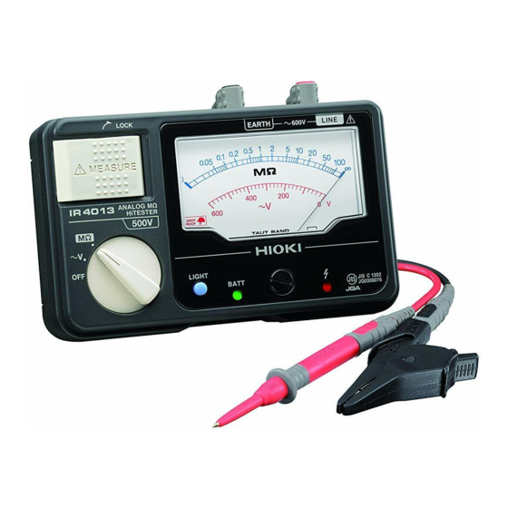
第 1 章 概要 1.3 各部の名称と機能 アナ グメグオ ム イテスタ 正面 * イラストは IR4042 です。 アース側測定端子 MEASURE キー ライン側測定端子 赤色のテストリード 黒色のテストリード 絶縁抵抗測定のとき を接続します。 を接続します。 に押します。 端子(上部) L9788-10 スイッ チ付きリードを制 御する端子です。 指針 メータ部 活線警告表示 ファンクションスイッチ 測定機能を切り替えます。 測定端子に電圧が存在し ているときに点灯します。 LIGHT キー メータ零位調整器 メータ照明を点灯... -
Page 17: 携帯用ケースの使用方法
第 1 章 概要 1.4 携帯用ケースの使用方法 • 上面の OPEN マークの記してある側のボタンを外します。 外したカバーを背面に回して留めます。 • ストラップを下図のように取り付けると、 本器を首にかけてご 使用いただくことができます。 携 帯 ケー ス 左側 の スト ラ ッ プ を 固 定 し て い る ボタンを外します。 携 帯 ケー ス 右側 の スト ラップのボタンを外し、... - Page 18 第 1 章 概要 携帯用ケース内の収納について L9787 テストリードのワニ口ク リップを差し込んで収納できます。 本器の下に取説を テストリードのキャップ 収納できます。 を収納できます。 テストリードの先端金属ピンには、取り外し可能なキャップが 装着されています。 短絡事故を防ぐため、測定カテゴリ CAT Ⅲで測定するときは、 必ずキャップをつけて使用してください。CAT Ⅰと CAT Ⅱで 測定するときは、キャップを外して使用してください。 OFF になっているブレーカの二次側は CAT I です。 測定カテゴリについては、取扱説明書の「測定カテゴリについ て」( p.6) を参照してください。 キャップを装着して測定する場合、キャップを損傷しないよう に注意してください。 測定中に不用意にキャップが外れた場合などは、感電事故を防 ぐため取り扱いには十分注意してください。...
-
Page 19: 第 2 章 測定方法
第 2 章 測定方法 測定方法 第 2 章 ファンクションスイッチが OFF、 ~ V 以外の位置では、 電池残 量表示が点灯していない場合でも MEASURE キーを押すと電 圧が出力されますので、感電に注意してください。 2.1 測定前の準備 電池を取り付ける。( p.44) EARTH 側測定端子に黒色のテストリード、LINE 側測定 端子に赤色のテストリードを接続する。 指針の零位を調整する。 ファンクションスイッチを OFF の位置にして、マイナス ドライバなどでメータ零位調整器を回し、指針を∞目盛の 中央に合わせます。 2.2 測定前の点検 電池残量を確認する。 ファンクションスイッチを OFF 以外の位置にセットし、 電 池有効範囲表示「BATT」が緑または赤に点灯することを... -
Page 20: L9788-10 スイッチ付きリードを
第 2 章 測定方法 (1) ファンクションスイッチを絶縁抵抗レンジにセットします。 (2) テストリードの先端を短絡します。 MEASURE キーを押し、 指針が 0 MΩ を指示することを確認 します。 2.3 L9788-10 スイッチ付きリードを 使用する L9788-10 を絶縁抵抗計に接続した場合も、本体の MEASURE キーは有効となっています。 L9788-10 を本体に接続した状態で、 本体の MEASURE キーを押しても試験電圧が出力されますの でご注意ください。 各部の名称と機能 : MEASURE キー 判定表示器 絶縁抵抗測定のときに押します。本体の活 コンパレータの判定結果を表 線警告表示と連動して赤色に点灯します。 示します。PASS のときは緑 色、FAIL のときは赤色に点灯 します。... - Page 21 第 2 章 測定方法 本体の電源が OFF になっていることを確認します。 L9788-10 スイッチ付きリードのプラグを、 本体の LINE 端 子側に根元までしっかり差し込みます。 始業前点検 L9788-10 を使用する前に、下記事項を必ず確認してくだ さい。 a. テストリードの先端を短絡します。 b. 本体のファンクションスイッチを絶縁抵抗レンジに セットします。 c. L9788-10 の MEASURE キーを押し、本体の活線警 告表示と連動して L9788-10 の MEASURE キーが赤 色に点灯すること、 指針が 0 MΩ を指示することを確 認します。 d. 本体の LIGHT キーを押し、 L9788-10 の先端のライト が点灯することを確認します。...
-
Page 22: 絶縁抵抗を測定する
第 2 章 測定方法 2.4 絶縁抵抗を測定する 電路や機器の絶縁度を調べるために、本器で絶縁抵抗を測定し ます。測定に際し、被測定物に印加する電圧を選ぶ必要があり ます。 感電、短絡事故または本器の破損を避けるため、下記のことを お守りください。 • 絶縁抵抗の測定中、測定端子に危険な電圧が発生しています。 テストリードの金属部に触れないでください。 • 測定後すぐに被測定物にさわらないでください。 • 測定後は本器の放電機能により被測定物の電荷を放電させて ください。( p.21) • 活線状態で絶縁抵抗測定しないでください。また被測定物の 電源を切ってから使用してください。 • 絶縁抵抗は印加電圧と漏れ電流の比です。被測定物に よっては表示値が安定しない場合がありますが、故障 ではありません。 • MEASURE キーは、活線警告表示が点灯するまで十分 に押してください。押し方が不十分な場合、正しい測 定ができません。 • 使用後はファンクションスイッチの位置をOFFにして ください。 • 試験電圧よりも耐電圧の低い機器、および耐電圧の不 明な機器・部品の接続されている電路を試験するとき には、それらを電路より外して測定することをお薦め します。... -
Page 23: 絶縁抵抗の測定方法
第 2 章 測定方法 2.4.1 絶縁抵抗の測定方法 測定ラインのブレーカは必ず " 切 " にします。 電源側 (一次側) 負荷側 (二次側) (例)電路と大地間の絶縁抵抗を測定する場合 ファンクションスイッチを IR4011 ~ 4015 では 、 IR4030~ 4042、 IR4082では試験電圧のいずれかにセッ トします。 黒色のアースリードを接地側に接続します。 赤色のラインリードを被測定物に接続します。 MEASURE キーを押します。 連続測定する場合はキーを引き起こします。 指針が安定してから、選択したレンジの目盛りの数値を読 み取ります。 測定後、放電します。( p.21) 測定中に他のファンクションや定格電圧に切り替えな いでください。... -
Page 24: 測定端子電圧特性
第 2 章 測定方法 2.4.2 測定端子電圧特性... -
Page 25: 放電機能
第 2 章 測定方法 2.5 放電機能 容量成分をもったものを測定すると、この容量成分に定格測定 電圧に相当する電荷が充電されたままになり、感電事故の可能 性があります。測定後は、次の手順で放電させてください。 テストリードを被測定物から離さずに MEASURE キーを OFF にします。 本器内の放電回路により、被測定物に残った電荷を自動的 に放電します。 ( 放電中は指針が に戻る速度が遅くなります) ∞ 指針が 目盛に戻ると放電は終了です。 ∞ (放電時間は容量の大小によって異なります。 )... -
Page 26: 接地抵抗を測定する (Ir4082 の機能
第 2 章 測定方法 2.6 接地抵抗を測定する (IR4082 の機能) IR4082 の交流抵抗レンジで、簡易測定法(2極法)により接地 電極(D 種接地工事、キュービクルの接地工事)の接地抵抗を 測定することができます。 2.6.1 D 種接地工事の接地抵抗を測定する 簡易測定法(2極法)とは? 簡易測定法とは、補助接地棒を打ち込めない場合に補助電極 として既設の低接地抵抗体を利用して接地抵抗を求める方法 で、主に D 種接地工事(判定基準 100 Ω)のチェックに利 用される方法です。 この方法では、測定原理上、測定対象と既設の接地抵抗体の 接地抵抗の和(Rx + Ro)が測定値となります。このため、 利用する既設の接地抵抗体の接地抵抗は、測定対象の接地抵 抗よりも十分に低くなければなりません。 通常、商用電源のニュートラル側は、 柱上変圧器で B 種接地 工事(数+ Ω 程度以下)が施されているため、通常、簡易測 定に利用できますが、接地抵抗が高い場合もありますので注 意してください。 この測定には商用電源のニュートラル側を利用します。接続前... - Page 27 第 2 章 測定方法 • MEASURE キーを押した状態で、 活線状態のライン-アース 間に本器を接続すると、漏電ブレーカが作動して停電を引き 起こします。本器をライン-アース間に接続しないでくださ い。誤って活線に接続した場合、本器の保護回路が動作しま す。再び測定できるようになるまでに約5秒かかります。 • 感度電流 5 mA 未満の漏電遮断器や漏電リレーが動作する可 能性がありますので、 5 mA 未満の漏電遮断器や漏電リレーが 設置されている場所ではこの方法で測定しないでください。 • 交流抵抗測定機能は、インダクタンス成分の小さな接地抵抗 を測定するための機能です。このため、3 mH 以上のインダ クタンス成分が直列接続された抵抗を測定すると正確な測定 値が得られない場合があります。 接地抵抗測定前に地電圧チェックをおこなう必要があります。 ファンクションスイッチを地電圧にセットします。 黒色のアースリードを測定したい接地電極に接続します。...
- Page 28 第 2 章 測定方法 赤色のラインリードをブレーカのニュートラル側に接続 します。 指針がメータの " 地電圧 OK" の範囲を指示することを確認 します。 ファンクションスイッチを Ω × 1、Ω × 10 のいずれか にセットします。 メジャーキーを押します。連続測定する場合はキーを引き 起こします。 指針が安定してから、 EARTH Ω の目盛りの数値を読みと ります。 読み取った数値に選択したレンジの倍率をかけた値が測 定値(Rx + Ro)です。 地電圧チェックの帯よりも左側を指示する場合は、IR4082 が 許容できる地電圧を超えているため測定ができません。 この場合、大きな漏洩電流が流れている可能性がありますので、 絶縁抵抗試験、漏洩電流試験をおこなってください。 地電圧に IR4082 の測定電流周波数と同じ周波数成分が含まれ ていると指針がふらつく場合がありますが、この場合は、ふら つきの中心値を読み取ってください。...
- Page 29 第 2 章 測定方法 家庭用 PV(太陽光発電)の D 種接地の測定 家庭用 PV のパネルは大地から絶縁されていますが、図のよう に架台やパワコンは接地(D 種)されています。これらの接地 抵抗も商用電源のニュートラル側(B 種設置工事)を利用した 簡易測定法で測定することができます。 太陽光パネル パワコン DC AC 商用電源のニュートラル側 産業用 PV は 300 V を超える場合が多く、 C 種接地工事になり ますので、簡易測定法では測定できません。...
-
Page 30: 測定する
第 2 章 測定方法 2.6.2 キュービクル内の B 種接地工事を測定する キュービクル内に A 種と B 種がある場合、キュービクルの B 種接地工事の接地抵抗を測定できます。 キュービクル内の B 種接地工事の抵抗値の閾値は電力会社に よって決められています。 一般的に数十Ωから100 Ω程度です。 キュービクルは高圧線を引き込むので、通常、A 種接地があり、 この接地抵抗は 5 Ω 程度です。 図のように A 種と B 種間で 2 極法測定すると、測定値は A 種 と B 種の和になりますが、 A 種が B 種に比べて十分小さいので、 B 種接地を測定していることになります。... - Page 31 第 2 章 測定方法 ファンクションスイッチを地電圧にセットします。 黒色のアースリードを測定したい B 種接地の接地端子に 接続します。 赤色のラインリードを A 種接地の接地端子に接続します。 指針がメータの”地電圧 OK” の範囲を指示することを確 認します。 ファンクションスイッチを Ω × 1、Ω × 10 のいずれか にセットします。 メジャーキーを押します。連続測定する場合はキーを引き 起こします。 指針が安定したから、 EARTHΩ の目盛りの数値を読み 取ります。 読み取った数値に選択したレンジの倍率をかけた値が測 定値(A 種+ B 種)です。...
-
Page 32: 電圧を測定する
第 2 章 測定方法 2.7 電圧を測定する 商用電源の交流電圧を測定できます。絶縁抵抗測定前に、被測 定物が活線でないことを確認する場合にも使用できます。 • テストリードは、必ずブレーカの二次側に接続してください。 ブレーカの二次側は、万一短絡があっても、ブレーカにて保 護します。一次側は、電流容量が大きく、万一短絡事故が発 生した場合、損傷が大きくなるので、測定しないでください。 • 最大入力電圧、対地間最大定格電圧はともに AC 600 Vrms (IR4030 は AC150 Vrms)です。これを超えると本器を破 損し、人身事故になるので測定しないでください。 • 感電事故を防ぐため、テストリードの先端で電圧のかかって いるラインを短絡しないでください。 電圧測定中に MEASURE キーを押さないでください。回路が 破損し、人身事故になります。... - Page 33 第 2 章 測定方法 電源側 (一次側) EARTH 注意 : MEASURE キーは押しません。 LINE 負荷側 (二次側) 注意:必ずブレーカ の 二次 側に 接続 し てください。 (例)電路と大地間の電圧を測定する場合 ファンクションスイッチを~ V にセットします。 黒色のアースリードを接地側に接続します。 赤色のラインリードをブレーカの LINE 側に接続します。 指針が安定してから値を読み取ります。 • 測定中に他のファンクションに切り替えないでくださ い。 • 正弦波以外の波形では誤差を生じます。...
-
Page 34: オートパワーセーブ(省電力機能
第 2 章 測定方法 2.8 オートパワーセーブ(省電力機能) 使用後は MEASURE キーを OFF にしてください。 オー トパワーセーブではわずかな電池消耗があります。 ファンクションスイッチが OFF 以外の位置にあるとき、最後に MEASURE キーを押した時点から約 15 分後に自動的にオート パワーセーブ状態になり、電池有効範囲表示が消灯します。 なお、オートパワーセーブ機能は解除できません。 パワーセーブ状態からの復帰方法 ファンクションスイッチを1度 OFF にしてから、元の位置に戻 します。... -
Page 35: 第 3 章 仕様
第 3 章 仕様 仕様 第 3 章 基本仕様 絶縁抵抗測定 測定原理 :直流電圧印加、電流検出 交流電圧測定 整流方式 :平均値整流実効値指示(半波整流) 機能 交流抵抗測定(IR4082 のみ) 測定原理 :交流定電流印加、電圧検出(同期検 波) 、実効抵抗値指示 (2極法による接地抵抗測定に利用可能) LINE 端子- EARTH 端子間に AC20 V 以上、 また 活線警告表示 は、自動放電中に DC20 V 以上の電圧が存在して いるときに赤色 LED が点灯する 絶縁抵抗測定後に測定対象の容量成分に蓄えられ 自動放電... - Page 36 第 3 章 仕様 一般仕様 確度保証期間 1 年 製品保証期間 3 年 使用場所 屋内使用、汚染度 2、高度 2000m 以下 保存温湿度範囲 -10 ℃~ 50 ℃、90%rh 以下、結露無きこと IP コード IP40 AC600 V(IR4030 のみ AC150 V) 端子間最大定格電圧 (交流電圧ファンクション) AC600V 対地間最大 測定カテゴリ Ⅲ、予想される過渡過電圧 6000 V 定格電圧 (IR4030 は AC150 V、測定カテゴリ Ⅲ、 予想される過渡過電圧...
- Page 37 第 3 章 仕様 ã§íþédól 公称系統電圧 AC 600 V max.(IR4030 は AC150 V max) 公称系統周波数 50/60 Hz 電池有効範囲 4.5 V ~ 6.8 V 定格動作条件 ・周囲温度 :0 ~ 40 ℃ ・相対湿度 :90%rh 以下(結露無きこと) ・外部磁界 :400 A/m 以下 ・姿勢 :水平± 30° ・電池電圧 :電池有効範囲...
- Page 38 第 3 章 仕様 ・湿度の影響 :第 1 有効測定範囲において 表示値の± 5% (90%rh 以下) :第 2 有効測定範囲において 表示値の± 10% 上記の影響量 かつ 許容差以内 ・外部磁界の影響 :表示値の± 3% (400 A/m) ・姿勢の影響量に :表示値の± 15% よる変動(E ) 0MΩ,∞目盛においては目盛の長さ の± 2% (水平± 30°) ・供給電圧の影響 :表示値の±5%かつ仕様許容差内(電池有効範囲 量による変動 において) (E ) 固有不確かさ (A) :±...
- Page 39 第 3 章 仕様 機種別仕様 形名 IR4041 定格測定電圧 (DC) 50 V 125 V 250 V 500 V 有効最大表示値 100 MΩ 中央表示値 2 MΩ 測 第 1 有効測定範囲 0.1 MΩ ~ 50 MΩ 定 絶 範 0.01 MΩ ~ 0.1 MΩ 未満 第...
- Page 40 第 3 章 仕様 形名 IR4030 定格測定電圧 (DC) 25 V 50 V 125 V 有効最大表示値 20 MΩ 中央表示値 0.5 MΩ 絶 測 第 1 有効測定範囲 0.02 MΩ ~ 10 MΩ 縁 定 抵 範 0.005 MΩ ~ 0.02 MΩ 未満 抗...
- Page 41 第 3 章 仕様 形名 IR4032 定格測定電圧 (DC) 125 V 250 V 500 V 有効最大表示値 100 MΩ 中央表示値 2 MΩ 絶 測 縁 第 1 有効測定範囲 0.1 MΩ ~ 50 MΩ 定 抵 範 抗 0.01 MΩ ~ 0.1 MΩ 未満 第...
- Page 42 第 3 章 仕様 形名 IR4011 IR4012 IR4013 IR4014 IR4015 定 格 測 定 電 圧 125 V 250 V 500 V 500 V 1000 V (DC) 有効最大表示値 100 MΩ 1000 MΩ 2000 MΩ 中央表示値 2 MΩ 20 MΩ 50 MΩ 第...
- Page 43 第 3 章 仕様 形名 IR4082 定格測定電圧 (DC) 125 V 250 V 500 V 有効最大表示値 100 MΩ 中央表示値 2 MΩ 絶 測 縁 第 1 有効測定範囲 0.1 MΩ ~ 50 MΩ 定 抵 範 0.01 MΩ ~ 0.1 MΩ 未満 抗...
- Page 44 第 3 章 仕様 測定レンジ × 1 × 10 対地間容量の影響 ~ 10nF 以下 仕様許容差内 10nF超~20nF以下 ± 24 Ω 交 20nF超~30nF以下 ± 48 Ω 仕様許容差内 流 30nF超~40nF以下 ± 72 Ω 抵 40nF超~50nF以下 ± 120 Ω 抗 50nF超~100nF以下 測 100nF 超~200nF 以下 ±...
-
Page 45: 第 4 章 保守・サービス
第 4 章 保守・サービス 保守・サービス 第 4 章 4.1 困ったときは • 故障と思われるときは、 「修理に出される前に」 ( p.42) を確 認してから、お買上店(代理店)か最寄りの営業所にご連絡 ください。 • 本器を輸送するときは、 輸送中に破損しないように梱包し、 故 障内容も書き添えてください。輸送中の破損については保証 しかねます。 本器の確度維持あるいは確認には、定期的な校正が必要です。 4.2 本器のクリーニング 本器の汚れをとるときは、柔らかい布に水か中性洗剤を少量含 ませて、軽くふいてください。ベンジン、アルコール、アセト ン、エーテル、ケトン、シンナー、ガソリン系を含む洗剤は絶 対に使用しないでください。変形、変色することがあります。... - Page 46 第 4 章 保守・サービス 修理に出される前に 動作がおかしいときは以下の項目をチェックしてください。 症状 確認項目 テストリードが断線している。 指針がまったく振 →テスタでテストリードの導通をチェックして れない。 ください。 スイッチ付きリー テストリードがしっかりと接続されていない。 ド の MEASURE →テストリードと本体との接続、 および、 EARTH キ ー が 動 作 し な 側テストリード先端の接続を確認してくださ い。 い。( p.17) 電池有効範囲表示 ニッケル水素電池、 マンガン電池を使用している。 がすぐに赤色にな →アルカリ電池に交換してください。 る。 絶縁抵抗ファンク シ ョ ン で テ ス ト リード先端を短絡...
- Page 47 第 4 章 保守・サービス 症状 確認項目 スイッチ付きリー ( p.17) の図のようにスイッチ付きリードを根 ド の MEASURE 元までしっかりと接続してください。隙間がある キーがきかない。 と MEASURE キーが動作しません。 測定対象近隣の充電回路からの誘導電圧(ノイ ズ)の影響 →近隣の充電回路のブレーカも切ってください。 測 定 値 が ふ ら つ 切れない場合は、もっとも低い測定値を測定結 く。また、他の絶 果として採用してください。 縁抵抗計で測定し た測定値と測定結 測定対象の容量成分(コンデンサ)が大きい。 果が異なる。 →コンデンサを外せる場合は外して測定してく ださい。外せない場合は、もっとも低い測定値 を測定結果として採用してください。 絶縁物の分極 の影響 →...
-
Page 48: 電池を交換する
第 4 章 保守・サービス 4.3 電池を交換する • 感電事故を避けるため、 ファンクションスイッチの位置をOFF にし、テストリードを外してから電池を交換してください。 • 交換後は、必ずカバーをしてネジを留めてから 使用してくだ さい。 • 新旧および異種の混合はしないでください。また極性+-に 注意し、逆挿入しないでください。性能劣化や液漏れの原因 になります。 • 使用済の電池をショート、充電、分解または火中への投入は しないでください。破裂する恐れがあり危険です。 • 使用済の電池は地域で定められた規則に従って処分してくだ さい。 • 電池の液漏れによる腐食を防ぐため、長い間使用しな いときは、電池を抜いて保管してください。 • 電池は必ずアルカリ乾電池をご使用ください。マンガ ン、ニッケル水素、オキシライド等は使用しないでく ださい。 本体裏側 電池カバー 留めネジ ファンクションスイッチを OFF にし、安全のためテストリードを 本体から外します。 本体裏側中央部の留めネジをゆるめ、電池カバーを外します。 電池 4 本を全部交換します。 電池カバーを取り付け、ネジ留めします。... -
Page 49: を交換する
第 4 章 保守・サービス 4.4 L9788-10 の先ピン(オプション) を交換する L9788-10 スイッチ付きリード(オプション)の先端のピンが磨 耗したり、折れた場合には交換することができます。 交換に必要な先ピンは HIOKI 代理店からお買い求めください。 (L9788-90 先ピン) 絶縁抵抗計の電源を OFF にし、本器を取り外します。 ソケットをスパナ(7 mm 幅)で回し取り外します。 先ピンを取り外します。 取り外すとき 先ピンを新しいものに交換し、 ソケットをスパナで回して L9788- 10 に取り付けます。 (締付けトルク:0.3 N ・ m) 動作確認をします。 既知の測定対象物を測定し、 抵抗値が正確であ るか確認してから使用してください。... - Page 50 第 4 章 保守・サービス...
- Page 51 付 付録 測定原理 1. 絶縁抵抗測定 測定対象の絶縁抵抗 Rx は、測定対象に電圧 V を印加、この ときに測定対象に流れる漏れ電流 I と印加電圧 V を測定し、 (印加した電圧 V)/(漏れ電流 I)から求めています。 2. 交流電圧測定 測定対象の電圧源から、本器に流入する電流値を電圧値に換 算して求めています。 出力電圧の極性について IR4000 シリーズの出力電圧極性は、 EARTH (黒) 側が+、 LINE (赤) 側が-になっています。 これは、 日本工業規格 JIS C 1302 「絶縁抵抗計」で上記の極性にするように定められているためで す。 従来から、LINE 端子(赤)は絶縁抵抗計の測定用電源の-極側 に、EARTH 端子(黒)は+極側に接続されるように規定されて...
- Page 52 付 活線(充電部)への絶縁抵抗計の接続について IR4000 シリーズは、 電圧出力状態で、 最大定格電圧の 1.2 倍の 電圧 (たとえば最大定格電圧が 500 V の製品では 600 V) の活 線に誤って接続してしまった場合(10 秒以内)でも故障しませ ん。しかし、接続された測定対象の回路には、絶縁抵抗計の定 格電圧が印加されるか、 または、 製品仕様に記載の短絡電流 (直 流)が流れることになり、測定対象の回路に故障を引き起こす 可能性がありますので、必ず活線でないことを確認してから接 続してください。 電路の試験電圧と主な使用例 • 社団法人日本電気協会が作成した民間規程である「内線規定」 には次のように記載されています。 第 1 章 1345 節 -1. 絶縁抵抗計の電圧 1345 節 -2 の注 6 低圧電路の絶縁抵抗を測定する絶縁抵抗計は、電路の使用電圧...
- Page 53 付 • 日本工業規格 JIS C 1302「絶縁抵抗計」の解説には次のよう に記載されています。 定格測定電圧 使用例 25 V/50 V 電話回線用機器、電話回線電路の絶縁測定 100 V 系の低電圧配電路および機器の維持・管理 100 V/125 V 制御機器の絶縁測定 250 V 200 V 系の低圧電路および機器の維持・管理 600 V 以下の低電圧配電路および機器の維持・管理 500 V 600 V 以下の低電圧配電路の竣工時の検査 600 V を超える回路および機器の絶縁測定 1 000 V 常時使用電圧の高い高電圧設備(例えば、高圧ケーブル、高電圧 機器、高電圧を用いる通信機器および電路)の絶縁測定...
- Page 54 付 絶縁物の性質 絶縁物には一般的に以下の性質があります。 ○温度によって抵抗値が変化する。 温度が高いほど抵抗値が下がります。絶縁抵抗の経年変化に より劣化を診断するような場合は、同じ温度で測定した抵抗 値、または、温度補正した抵抗値を使う必要があります。 ○測定する電圧によって抵抗値が変化する。 高い電圧を印加して測定するほど抵抗値が下がります。この 性質があるため、測定対象が使用される電圧と同程度以上の 電圧で測定しなければなりません。 ○吸湿により抵抗値が下がる。 高湿度下では抵抗値が大幅に下がります。このため、雨天で は極端に低い抵抗値となる場合があります。 また、絶縁物が結露している場合には、大きな電流が絶縁物 表面を漏れてしまうため、絶縁抵抗を測定することができま せん。...
- Page 55 IR4011, IR4012, IR4013, IR4014, IR4015, IR4030, IR4031, IR4032, IR4033, IR4041, IR4042, IR4082...
- Page 57 IR4011~IR4015 3415 IR4030~IR4033 3415-01 IR4041~IR4042 3415-02 IR4082 TEMPERATURE ANALOG M HiTESTER XXXX 製品名 HiTESTER Instruction Manual...
- Page 59 Contents Contents Introduction ............... 1 Verifying Package Contents........1 Options..............3 Safety Information ............. 4 Operating Precautions ..........7 Chapter 1 Overview Names and Functions of Parts ....11 Using a Carrying Case ......12 Chapter 2 Measurement Procedures Preparing for Measurement....... 13 Pre-measurement inspection ....
- Page 60 Contents Chapter 3 Specifications Chapter 4 Maintenance and Service Troubleshooting ........37 Replacing Batteries ........38 Replacing the Pin (Option) ......39 Cleaning ............ 40...
-
Page 61: Introduction
Introduction Introduction Thank you for purchasing the HIOKI Model IR4000series ANA- LOG M HiTESTER. To obtain maximum performance from the instrument, please read this manual first, and keep it handy for future reference. The “instrument” in this manual means IR4011, IR4012, IR4013, IR4014, IR4015, IR4030, IR4031, IR4032, IR4033, IR4041, IR4042 or IR4082. - Page 62 *1: IR4082 has -11 only. *2: L9787 Test Lead, L9788-10 Test Lead with Remote Switch and L9788-11 Test Lead Set with Remote Switch are all exclusively designed for the HIOKI IR4000 ANALOG M HiTESTER series. Do not use for any other purpose.
-
Page 63: Options
L9788-11 Complete Test Lead. □ C0100 Carryingcase L9787 Test Lead, L9788-10 Test Lead with Remote Switch and L9788-11 Test Lead Set with Remote Switch are all exclusively designed for the HIOKI IR4000 ANALOG M HiTESTER series. Do not use for any other purpose. -
Page 64: Safety Information
Safety Information Safety Information This instrument is designed to comply with IEC 61010 Safety Standards, and has been thoroughly tested for safety prior to shipment. However, mishandling during use could result in injury or death, as well as damage to the instrument. - Page 65 Safety Information The following symbols in this manual indicate the relative impor- tance of cautions and warnings. Indicates that incorrect operation presents an extreme hazard that could result in serious in- jury or death to the user. Indicates that incorrect operation presents a significant hazard that could result in serious injury or death to the user.
- Page 66 Safety Information Measurement categories This instrument complies with CAT III safety requirements. To ensure safe operation of measurement instruments, IEC 61010 establishes safety standards for various electrical envi- ronments, categorized as CAT II to CAT IV, and called measure- ment categories. CAT II: Primary electrical circuits in equipment connected to an AC electrical outlet by a power cord (portable tools, household appliances, etc.)
-
Page 67: Operating Precautions
Before using the instrument the first time, verify that it operates normally to ensure that no damage occurred during storage or shipping. If you find any damage, contact your dealer or Hioki representative. To prevent an electric shock accident, confirm that the white or red portion (insulation layer) inside the cable is not exposed. - Page 68 Operating Precautions Setting up the Instrument Operating temperature and humidity/Accuracy guarantee for temperature and humidity. ( p.29) Avoid the following locations that could cause an accident or damage to the instrument. In the presence of Exposed to direct corrosive or explosive sunlight gases Exposed to high...
- Page 69 Operating Precautions • The maximum rated voltage between input terminals and ground is 600 V AC (150 V AC for model IR4030). Attempting to measure voltages exceeding 600V AC (150 VAC for model IR4030) with respect to ground could damage the instrument and result in personal injury.
- Page 70 Operating Precautions • This instrument is designed for use indoors. It can be oper- ated at temperatures between 0 and 50°C without degrading safety. • For safety reasons, when taking measurements, only use the L9787, L9788-11 or optional test lead provided with the instru- ment.
-
Page 71: Chapter 1 Overview
Chapter 1 Overview Chapter 1 Overview 1.1 Names and Functions of Parts Front *This figure is model IR4042. LINE terminal EARTH terminal MEASURE key Connect the Connect the black Press to measure red test lead test lead insulation resistance Terminals (on top) Terminals Insulation... -
Page 72: Using A Carrying Case
Chapter 1 Overview 1.2 Using a Carrying Case Undo the snap fastener on OPEN mark side. Lift the cover and pivot it to the side and under the case itself and redo the snap fastener on the side of the cover. Fasten the strap as shown below. -
Page 73: Measurement Procedures
Chapter 2 Measurement Procedures Measurement Chapter 2 Procedures When the function selector is at the position other than OFF or V and even with the effective battery range indicator OFF, if you press the MEASURE key, the volt- age will be output. Be careful of electric shock. 2.1 Preparing for Measurement Insert the batteries. -
Page 74: Pre-Measurement Inspection
Chapter 2 Measurement Procedures 2.2 Pre-measurement inspection Confirming the battery power. Set the function selector away from OFF and confirm the effective battery range indicator. Battery power is high when a green light is shown. Battery power is low when a red light is shown and replacement is recommended. -
Page 75: Using The L9788-10 Test Lead With
Chapter 2 Measurement Procedures 2.3 Using the L9788-10 Test Lead with Remote Switch The Insulation Resistance Tester’s MEASURE key will still be available even when this test lead is connected to the Insulation Resistance Tester. When connected to the Insulation Resistance Tester, take note that a test voltage will be discharged even when the MEASURE key of the Tester is pressed. - Page 76 Chapter 2 Measurement Procedures Confirm that the power of the Insulation Resistance Tester is turned off. Plug the test lead securely into the LINE terminal of the Insulation Resistance Tester. Before Starting (Before using the test leads, be sure to conduct the following safety checks.) a.
-
Page 77: Insulation Resistance Measurement
Chapter 2 Measurement Procedures 2.4 Insulation Resistance Measurement The instrument is used to measure insulation resistance in the electric circuit or in the appliance in order to inspect the degree of electrical insulation. When measuring insulation resistance, you have to select the voltage applied to the object to be measured. Observe the following to avoid electric shock, short cir- cuits and damage to the instrument: •... - Page 78 Chapter 2 Measurement Procedures Measurement Method Always turn off the breaker of the measurement line. Source (primary side) Load (secondary side) Ex. When measuring the insulation resistance between circuit and ground For the IR4011 to 4015, set the function selector to For the IR4030 to 4042 and IR4082, set the function selector to any of the test voltages.
-
Page 79: Discharging Function
Chapter 2 Measurement Procedures Discharging Function When measuring an insulation resistance that contains a capac- itance element, a charge proportional to the measurement volt- age accumulates, and if undischarged could lead to an electric shock accident. Without removing the test leads from the item being mea- sured, release the MEASURE key. -
Page 80: Earth Resistance Measurement (Function Of Ir4082)
Chapter 2 Measurement Procedures Earth Resistance Measurement (Function of IR4082) In the AC resistance range of IR4082, the earth resistance of the ground electrode (D type earthing work) can be measured using the simple measurement method (bipolar method). What is the simple measurement method (bipolar method)? The simple measurement method is a method used to obtain the earth resistance by making use of the existing low earth resistor as an auxiliary electrode when the additional earth... - Page 81 Chapter 2 Measurement Procedures • When the instrument is connected to the Line-Earth section of the live conductor with the MEASURE key pressed down, the leakage breaker will be triggered and the power supply will be cut off. Do not connect the instrument to the Line-Earth sec- tion.
- Page 82 Chapter 2 Measurement Procedures Connect the red line lead to the neutral side of the breaker. Confirm that the indicator needle indicates the range of "Earth Voltage OK"of the meter. Set the Function selector to either x1, or x10. Press the Measure key. Pull it up for continuous measure- ments.
-
Page 83: Voltage Measurement
Chapter 2 Measurement Procedures 2.7 Voltage Measurement This instrument can measure the AC of commercial power. It is also useful to make sure the subject conductor is not live before measuring insulation resistance. • Test leads should only be connected to the secondary side of a breaker, so the breaker can prevent an acci- dent if a short circuit occurs. - Page 84 Chapter 2 Measurement Procedures Source Caution: (primary side) EARTH Do not press the MEASURE key. LINE Load (secondary side) Always connect the test lead to the secondary side of the breaker. Ex. When measuring the voltage between circuit and ground Use the function selector to select the V function.
-
Page 85: Auto Power Save (Power-Saving Function)
Chapter 2 Measurement Procedures 2.8 Auto power save (power-saving function) To avoid battery depletion, turn the MEASURE key OFF after use (the Auto Power Save feature con- sumes a small amount of current). When the function selector is not at OFF, the power save func- tion automatically kicks in 15 minutes after the last time the MEASURE key is pressed and the effective battery range indica- tor goes off. - Page 86 Chapter 2 Measurement Procedures...
- Page 87 Chapter 3 Specifications Chapter 3 Specifications Standard Specifications Insulation Resistance measurement: DC voltage supply, current detection AC Voltage measurement: Average responding type Functions AC resistance measurement (IR4082 only) Measurement principle, constant AC supply, volt- age detection (synchronous detection), effective resistance value indication (can be used in earth resistance measurement by bipolar method) When 20 VAC or higher exists between LINE termi- Live circuit indica-...
- Page 88 Chapter 3 Specifications General Specifications Guaranteed 1 year accuracy period Operating Indoors, Pollution Degree 2 Environment Altitude up to 2000 m (6562-ft.) 0 to 40C (32 - 104F) Operating 90%RH or lower (non-condensating) Temperature & 40 to 50C (104 - 122F), at 50C and below relative Humidity with linear decrease up to 50%RH Storage Tempera-...
- Page 89 Chapter 3 Specifications Accessories IR4011, IR4012,IR4013, IR4014, IR4015, IR4030, Name IR4031, IR4032, IR4033, IR4041, IR4042, IR4082* Model ‐ 11 Version L9788-11 Complete Test L9787 Test Lead×1 Leads with Remote Control Switch ×1 C0100 Carrying case ×1 Accessories Instruction manual ×1 LR6 alkaline battery ×...
- Page 90 Chapter 3 Specifications • Open circuit voltage 1 to 1.2 times of rated output voltage. (when no load is applied) • Rated current (DC) 1 mA (The current flow when rated output voltage is maintained.) 1 to 1.2 times of rated output current. •...
- Page 91 Chapter 3 Specifications Insulation Resistance Measurement Specifications of Each Model Model IR4041 Rated measurement 50 V 125 V 250 V 500 V voltage (DC) Maximum effective 100 M indicated value Center scale value 2 M 1st effective 0.1 M to 50 M measuring range 2nd effective 0.01 M...
- Page 92 Chapter 3 Specifications Model IR4030 Rated measurement 25 V 50 V 125 V voltage (DC) Maximum effective 20 M indicated value Center scale value 0.5 M 1st effective 0.02 M to 10 M measuring range 2nd effective 0.005 M to 0.02 M measuring range 10 M...
- Page 93 Chapter 3 Specifications Model IR4032 Rated measurement 125 V 250 V 500 V voltage (DC) Maximum effective 100 M indicated value Center scale value 2 M 1st effective 0.1 M to 50 M measuring range 2nd effective 0.01 M to 0.1 M measuring range 50 M...
- Page 94 Chapter 3 Specifications Model IR4011, IR4012, IR4013, IR4014, IR4015 Rated measurement 125 V 250 V 500 V 500 V 1000 V voltage (DC) Maximum effective 100 M 1000 M 2000 M indicated value Center scale value 2 M 20 M 50 M...
- Page 95 Chapter 3 Specifications IR4082 Model Insulation Resistance measurement Rated measurement 125 V 250 V 500 V voltage (DC) Maximum effective 100 M indicated value Center scale value 2 M 1st effective 0.1 M to 50 M measuring range 0.01 M to 0.1 M 2nd effective measuring range 50 M...
- Page 96 Chapter 3 Specifications Effect of Earth Capacity 10 nF or less within specifications ±24 10 nF - 20 nF ±48 20 nF - 30 nF within specifications ±72 30 nF - 40 nF ±120 40 nF - 50 nF 50 nF - 100 nF ±1.2 ...
-
Page 97: Chapter 4 Maintenance And Service
Service 4.1 Troubleshooting • If the instrument seems to be malfunctioning, contact your dealer or Hioki representative. • Pack the instrument so that it will not sustain damage during shipping, and include a description of existing damage. We do not take any responsibility for damage incurred during ship- ping. -
Page 98: Replacing Batteries
Chapter 4 Maintenance and Service 4.2 Replacing Batteries • To avoid electric shock, turn off the function selector and disconnect the test leads before removing the lith- ium battery. • After replacing the batteries, replace the cover before using the instrument. •... -
Page 99: Replacing The Pin (Option)
The pin at the front of the Model L9788-10 (option) can be replaced when it has worn away or is damaged. Replacement pins are available at any Hioki dealer. (Model L9788-90 Tip Pin) Turn off the power of the Insulation Resistance Tester and disconnect the test leads. -
Page 100: Cleaning
Chapter 4 Maintenance and Service 4.4 Cleaning To clean the instrument, wipe it gently with a soft cloth moist- ened with water or mild detergent. Never use solvents such as benzene, alcohol, acetone, ether, ketones, thinners or gasoline, as they can deform and discolor the case.
Need help?
Do you have a question about the Analog MO HiTESTER Series and is the answer not in the manual?
Questions and answers