Table of Contents
Advertisement
Quick Links
BT3563A
BT3562A
BT3561A
BT3563
BT3563-01
BT3562
BT3562-01
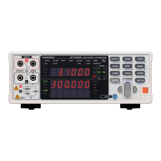
BATTERY HiTESTER
Be sure to read this manual before using the instrument.
When using the instrument for the
first time
Names and Functions of Parts
Measurement Preparations
Jan. 2021 Revised edition 9
BT3562A981-09 21-01H
Troubleshooting
p.11
Maintenance and Service
p.19
Error Display
HIOKI BT3562A981-09
Instruction Manual
p.3
p.189
p.191
EN
Advertisement
Table of Contents


Need help?
Do you have a question about the BT3563A and is the answer not in the manual?
Questions and answers