Table of Contents
Advertisement
Quick Links
Advertisement
Table of Contents

Related Manuals for Hioki 3174


Summary of Contents for Hioki 3174
- Page 1 INSTRUCTION MANUAL 3174 3174-01 AC AUTOMATIC INSULATION/ WITHSTANDING HiTESTER...
-
Page 3: Table Of Contents
Safety Information ..............2 Operating Precautions..............4 Chapter 1 Overview ___________________________________ 7 Product Overview ............7 Features ...............7 Names and Functions of Parts ........9 1.3.1 3174 (3174-01) ..............9 1.3.2 Display ................12 1.3.3 Model 9615 H.V.Test Lead ...........13 External Dimensions ..........14 Testing Process ............15 Chapter 2 Testing Arrangements ________________________ 17 Arrangements Work Flow ...........17... - Page 4 Contents 3.1.4 Setting the Ramp-up (Ramp-down) Time Timer ... 35 3.1.5 Setting the Test-Frequency .......... 36 3.1.6 Setting the Initial voltage for ramp-up ......37 3.1.7 Setting the Confirmation Voltage used for upper and lower-limits for Contact Check ..38 Starting a Test ............
- Page 5 Contents 6.1.2 Momentary Out .............80 6.1.3 Double Action ..............81 6.1.4 START Protection ............82 6.1.5 Output-Voltage Restricting ..........83 Display Hold (Hold Function) ........84 6.2.1 PASS Hold ..............85 6.2.2 FAIL Hold ..............86 6.2.3 STOP Hold ..............87 Evaluate even for forced termination of test ....88 Continue testing even after FAIL result is shown (Continuous Test Mode, Only Withstanding-Test) ..89 Limiting the FAIL Hold Cancellation (FAIL mode) ..90...
- Page 6 Contents Specifications ............122 Connection and Setting Procedures ......123 9.2.1 Connecting the Connector .......... 123 9.2.2 Setting the Communication Conditions ....... 125 Communication Methods ......... 127 9.3.1 Message Format ............128 9.3.2 Output Queue and Input Buffer ........131 9.3.3 Status Byte Register ...........
-
Page 7: Contens
Introduction Introduction Thank you for purchasing the HIOKI “Model 3174, 3174-01 AC Automatic Insula- tion/Withstanding HiTester.” To obtain maximum performance from the instru- ment, please read this manual first, and keep it handy for future reference. Confirming Package Contents • When you receive the instrument, inspect it carefully to ensure that no dam- age occurred during shipping. -
Page 8: Safety Information
Safety Information Safety Information This instrument is designed to comply with IEC 61010 Safety Standards, and has been thoroughly tested for safety prior to shipment. However, mis- handling during use could result in injury or death, as well as damage to the instrument. - Page 9 Safety Information Other symbols This symbol indicates that the product conforms to safety regulations set out by the EC Directive. Indicates a prohibited action. ( p. ) Indicates the location of reference information. Indicates quick references for operation and remedies for trouble- shooting.
-
Page 10: Operating Precautions
Operating Precautions Operating Precautions Instrument Installation Operating temperature and humidity: 0 to 40°C at 80% RH or less (no condensation) Temperature and humidity range for guaranteed accuracy: 23±5°C, 80%RH or less (no condensation) after 10 minutes minimum warm-up Avoid the following locations that could cause an accident or damage to the instrument. - Page 11 Before using the instrument, make sure that the insulation on the test leads is undamaged and that no bare conductors are improperly exposed. Using the instrument in such conditions could cause an electric shock, so contact your dealer or Hioki representative for replacements. (Model 9615 H.V.Test Lead) Handling the Instrument •...
- Page 12 Operating Precautions...
-
Page 13: Chapter 1 Overview
Model 3174, 3174-01 AC Automatic Insulation/Withstanding HiTester is an affordable insulation/withstanding testing instrument equipped with stable volt- age supply and contact check functions to prevent a decrease in testing reliabil- ity caused by these factors. - Page 14 RS-232C (Standard Package)/GP-IB Interface (Standard Package for 3174-01 only) This instrument is equipped with RS-232C as a standard package and the 3174- 01 is also equipped with GP-IB as a standard package. By connecting to a com- puter, they allow for auto testing to be carried out and test results to be read.
-
Page 15: Names And Functions Of Parts
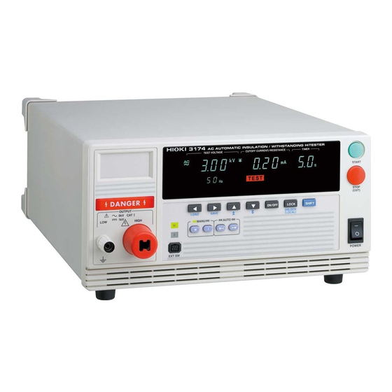
: Power on trol box (optional) : Power off HIGH Voltage output terminal The HIGH terminal is a high-volt- (The diagram shows a 3174 AC Au- age terminal for voltage outputs. tomatic Insulation/Withstanding HiTester.) LOW Voltage output terminal The LOW terminal is a low-volt- age terminal for voltage outputs. - Page 16 1.3 Names and Functions of Parts Operation Keys Moves the flashing cursor to the left. Moves the flashing cursor to the right. Raise the selected value with the flashing cursor. Lower the selected value with the flashing cursor. Change the ON/OFF for the selected setting with the flashing cursor.
- Page 17 LOW contact check terminal Used for buzzer sound adjustment. A low-voltage terminal for contact check. Two knobs are provided: one for PASS screening and one for FAIL screening. The diagram shows a 3174-01 (with GP-IB) AC Automatic Insulation/Withstand- ing HiTester.
-
Page 18: Display
1.3 Names and Functions of Parts 1.3.2 Display Test setting conditions and current status of the instrument are shown in the panel on front of the instrument. Upper-limit value icon Test time Test type Lower-limit value icon Ramp-up time Upper-limit test value Ramp-down time Test-voltage value Lower-limit test value... -
Page 19: Model 9615 H.v.test Lead
1.3 Names and Functions of Parts 1.3.3 Model 9615 H.V.Test Lead Explanations on names and parts of Test Lead. To prevent electric shock, when the DANGER lamp is lit or during the test, never touch the voltage output terminals, test lead, or the tested object. There is no insulation/withstand-voltage on the Alligator clip vinyl cover- ing. -
Page 20: External Dimensions
1.4 External Dimensions 1.4 External Dimensions Model 3174, 3174-01 AC Automatic Insulation/Withstanding HiTester... -
Page 21: Testing Process
1.5 Testing Process 1.5 Testing Process Explanation of the basic flow of withstanding and insulation-resistance tests. Testing Arrangements 1. Connect the protective conductor terminal. (p. 17) 2. Connect the power cord. 3. Connect the test lead. (Voltage output terminal, Contact check terminal) 4. - Page 22 1.5 Testing Process...
-
Page 23: Testing Arrangements
• The Remote Control Box to start or stop the test can be used. "Appendix1 Remote Control Box" (p. A1) • The instrument can be controlled with EXT I/O, RS-232C or GP-IB (only for 3174-01). "Chapter 8 External Interface" (p. 103) "Chapter 9 RS-232C/GP-IB Interface" (p. 121) -
Page 24: Connecting The Protective Conductor Terminal
2.2 Connecting the Protective Conductor Terminal 2.2 Connecting the Protective Conductor Termi- To carry out the test safely, connect the protective conductor terminal found on the back of the instrument to earth. If the ground-type double-pole power cord that is supplied with the instrument is used, the instrument is automatically grounded. -
Page 25: Connecting The Power Cord
2.3 Connecting the Power Cord 2.3 Connecting the Power Cord Connect the power cord to the power inlet on the back of the instrument and the plug to the wall socket to provide power to the instrument. To avoid electrical accidents and to maintain the safety specifications of this instrument, connect the power cord only to a 3-contact (two-conductor + ground) outlet. -
Page 26: Connecting The Test Lead
Using the instrument in such conditions could cause an elec- tric shock, so contact your dealer or Hioki representative for replace- ments. (Model 9615 H.V.TEST LEAD) • To avoid shock and short circuits, turn off power before connecting test leads. -
Page 27: When Using The Contact Check Function
2.4 Connecting the Test Lead 2.4.1 When using the Contact Check Function When using the Contact Check Function, connect the test lead as follows. On the usage of Contact Check, see "2.6 Pre-test Check" "3.1.7" "4.1.5 Set- ting the Confirmation Voltage used for upper and lower-limits for Contact Check". To prevent electric shock, when the DANGER lamp is lit or during the test,... - Page 28 2.4 Connecting the Test Lead Remove the slip protection plate of the termi- nals for Contact Check and connect the test leads in the same way as steps 2 to 4. Connect the test lead of the LOW Contact Check terminal to the tested object. Make sure the probe on the LOW Contact Check terminal side does not directly touch the probe on the LOW Voltage Output Termi-...
-
Page 29: When Not Using The Contact Check Function
2.4 Connecting the Test Lead 2.4.2 When not using the Contact Check Function When not using the Contact Check Function, connect the test lead as follows. When the front terminal is used Remove the LOW voltage output terminal The H.V. Test Lead by turning it counterclockwise. -
Page 30: Turning The Power On And Off
2.5 Turning the Power On and Off 2.5 Turning the Power On and Off Before turning the instrument on, make sure the supply voltage matches that indicated on the its power connector. Connection to an improper sup- ply voltage may damage the instrument and present an electrical hazard. To avoid damaging the power cord, grasp the plug, not the cord, when unplug- ging it from the power outlet. - Page 31 2.5 Turning the Power On and Off Turning Power On Front panel Turn the power switch to on ( The “3174” (model name) and software version are displayed on the screen. Model name Software version (This diagram shows version 1.00.) State of interface "rS.0": RS-232C 9600 bps...
-
Page 32: Pre-Test Check
The key is working properly if you feel the click. The key may be damaged if you do not feel the click. Contact your dealer or Hioki representative. Breaking current Before starting the withstanding test, check whether electric current has been shut out when the pre-set voltage is outputted. - Page 33 2.6 Pre-test Check Measured resistance Before starting the insulation-resistance test, check that the resistance value for measurement is the same as the pre-set value. Recommended Insulation: High voltage-high insulation flat chip resistors GS series (from KOA Corporation) or similar products Note the usage voltage and power.
- Page 34 2.6 Pre-test Check Self-testing of the Contact Check Function After finishing laying out the wires for the test, hold down the SHIFT key and press the START key to start the Contact Check self-testing (The wire layout for the test is the actual test wire layout or the wire layout used during the pre-test check).
-
Page 35: Withstand-Voltage Test
Withstand- Chapter 3 Voltage Test This chapter describes how to set withstand-voltage test conditions and the proper testing procedure. Read "Chapter 2 Testing Arrangements" (p. 17), and make the necessary preparations for testing. Refer to "Chapter 5 Automatic Test" (p. 69) for carrying out withstanding and insulation-resistance tests consecutively. - Page 36 Select the Withstand-voltage test mode Set test conditions "3.1.1 Setting the Test-Voltage Value" (p. 32) "3.1.2 Setting the Upper (Lower) Limit Value" (p. 33) "3.1.3 Setting the Test Time Timer" (p. 34) "3.1.4 Setting the Ramp-up (Ramp-down) Time Timer" (p. 35) "3.1.5 Setting the Test-Frequency"...
-
Page 37: Setting The Test-Conditions
3.1 Setting the Test-Conditions Setting the Test-Conditions For safety reasons, be sure to carry out pre-test check (p. 26) before setting the test conditions. Setting the test conditions. Pre-set test conditions can be retrieved to carry out the test. See "7.2 Loading the Test Conditions" (p. 102) Test setting When lights up on the screen, pressing the... -
Page 38: Setting The Test-Voltage Value
3.1 Setting the Test-Conditions 3.1.1 Setting the Test-Voltage Value Set a test-voltage value. When the test is started, the pre-set voltage will be sup- plied to the tested object from the voltage output terminal via the test lead. The test will not start if the load is large and the output voltage does not reach ±30 V of the set test-voltage. -
Page 39: Setting The Upper (Lower) Limit Value
3.1 Setting the Test-Conditions 3.1.2 Setting the Upper (Lower) Limit Value Set a upper-limit test value and a lower-limit test value. For example, when the upper-limit (lower-limit) test value is set at 10 mA, a “ ” will be shown PASS when a current less than (more than) 10 mA is supplied to the tested object. -
Page 40: Setting The Test Time Timer
3.1 Setting the Test-Conditions 3.1.3 Setting the Test Time Timer When the test time timer is set, the test will automatically run and stop when the time is up. If no test-time timer is required, set it to “OFF” using the ON/OFF key. -
Page 41: Setting The Ramp-Up (Ramp-Down) Time Timer
3.1 Setting the Test-Conditions 3.1.4 Setting the Ramp-up (Ramp-down) Time Timer Ramp-up time means the time to increase the voltage until it reaches the set test-voltage value set in the "Setting the Test-Voltage Value" (p.32). Ramp-down time means the time to decrease the voltage upon completion of the test time. When the ramp-up time and ramp-down time are set, the test voltage during the test can be controlled. -
Page 42: Setting The Test-Frequency
3.1 Setting the Test-Conditions 3.1.5 Setting the Test-Frequency In the withstand-voltage test, the test-frequency (50 Hz/ 60 Hz AC) can be selected. Press the key to move the flashing cursor to the test-frequency. Press the keys to set the test-frequency. <Ex.>... -
Page 43: Setting The Initial Voltage For Ramp-Up
3.1 Setting the Test-Conditions 3.1.6 Setting the Initial voltage for ramp-up When setting the voltage-raising time (ramp-up time), the initial value can be set by setting it as a proportion of the test voltage. The default value is 0.0 and the initial voltage for ramp-up is 0 V. -
Page 44: Setting The Confirmation Voltage Used For Upper And Lower-Limits For Contact Check
3.1 Setting the Test-Conditions 3.1.7 Setting the Confirmation Voltage used for upper and lower-limits for Contact Check Confirmation Voltage used for upper and lower-limits for Contact Check. Contact Check can be carried out by measuring the terminal voltage of the tested object. - Page 45 3.1 Setting the Test-Conditions Press the keys to set the lower-limit confirmation voltage for Con- tact Check. <Ex.> Set to 0.2 kV. Setting range: 0.20 to 5.00 kV (The value changes by 0.01 kV.) To change the value by 0.1 kV, while holding down the SHIFT key, press keys.
-
Page 46: Starting A Test
• There is a priority hierarchy for the START keys. Priority hierarchy: Remote Control Box > EXT I/O > Front panel of the 3174 (3174-01) Note that when a START key with a higher priority is in use, lower-priority keys are disabled. - Page 47 3.2 Starting a Test will not be displayed because the default factory setting for this Double action state instrument is Double Action. is not lit. Press the key once in the beginning. STOP When the STOP key is pressed, will be shown for 0.5 seconds. STOP To start the test, press the key when...
-
Page 48: Terminate The Test
3.3 Terminate the Test 3.3 Terminate the Test When the test-time is set Test will automatically stop when the test is carried out during the pre-set test time. Front panel When the test-time has not been set Press the STOP key to terminate the test. - Page 49 3.3 Terminate the Test Never touch the voltage output terminals, test lead, or the tested object until the DANGER lamp has gone off and the output voltage indicator shows 0.00V. Tested object When a test object that contains a capacity component is subjected to a test, the object might remain electrically charged, thereby causing an electric shock.
-
Page 50: Displaying The Test Result
3.4 Displaying the Test Result 3.4 Displaying the Test Result Even following a test, there may be a residual voltage at the output termi- nal. Therefore, to prevent electric shock, check the following before touch- ing the output-voltage terminal, test lead, or tested object, make sure that no high voltage is being applied between the output terminals. -
Page 51: Pass" Determination
3.4 Displaying the Test Result 3.4.1 "PASS" Determination Test is successful when lights up. In the initial setting, will light up for about 0.3 seconds before returning to READY mode. To hold the display See "6.2.1 PASS Hold" (p. 85) When test time is set, PASS will appear when the test has completed. -
Page 52: Fail" Determination
3.4 Displaying the Test Result 3.4.2 "FAIL" Determination Test is unsuccessful when lights up. display will be retained. (default condition) When a current 1.5 times higher than the upper-limit test value is flowing while performing a withstand-voltage test, the voltage is immediately blocked by the insulation circuit, resulting in an UPPER FAIL. -
Page 53: Insulation-Resistance Test
Insulation- Chapter 4 Resistance Test This chapter describes how to set insulation-resistance test condi- tions and the proper testing procedure.Read "Chapter 2 Testing Arrangements" (p. 17), and make the necessary preparations for testing. Refer to "Chapter 5 Automatic Test" (p. 69) for carrying out withstanding and insulation-resistance tests consecutively. - Page 54 Select the insulation-resistance test mode Set test conditions "4.1.1 Setting the Test-Voltage Value" (p. 50) "4.1.2 Setting the Upper (Lower) Limit Value" (p. 51) "4.1.3 Setting the Test Time Timer" (p. 53) "4.1.4 Setting the Delay Time" (p. 54) Starting a test Press the START key to start a test.
-
Page 55: Setting The Test Conditions
4.1 Setting the Test Conditions 4.1 Setting the Test Conditions For safety reasons, be sure to carry out pre-test check (p. 26) before setting the test conditions. Setting the test conditions. Pre-set the insulation-resistance test termination mode for the optional functions. See "6.7 Insulation-Resistance Test Termination Mode"... -
Page 56: Setting The Test-Voltage Value
4.1 Setting the Test Conditions 4.1.1 Setting the Test-Voltage Value Set a test-voltage value. When the test is started, the pre-set voltage will be sup- plied to the tested object from the voltage output terminal via the test lead. Select from 500 V and 1000 V. -
Page 57: Setting The Upper (Lower) Limit Value
4.1 Setting the Test Conditions 4.1.2 Setting the Upper (Lower) Limit Value Set a upper-limit test value and a lower-limit test value. For example, when the lower-limit (upper-limit) test value is set to 100 MΩ, a "PASS" will show if the measurement resistance value is more than (or below) 100 MΩ. - Page 58 4.1 Setting the Test Conditions Upper- or lower-value and Resolution Setting range Setting resolution (MΩ) (MΩ) 0.20 to 2.00 0.01 2.10 to 20.0 21.0 to 200 210 to 2000 Relationship between test voltage, lower-limit test values and ranges, measurement ranges Test voltage Lower-limit test Ranges...
-
Page 59: Setting The Test Time Timer
4.1 Setting the Test Conditions 4.1.3 Setting the Test Time Timer When the test time timer is set, the test will automatically run and stop when the time is up. If no test-time timer is required, set it to “OFF” using the ON/OFF key. -
Page 60: Setting The Delay Time
4.1 Setting the Test Conditions 4.1.4 Setting the Delay Time Time during which screening is not performed from the start of a test (delay time) can be set. This is effective when a tested object contains a capacity component. Press the key to move the flashing cursor to the test-time timer. -
Page 61: Setting The Confirmation Voltage Used For Upper And Lower-Limits For Contact Check
4.1 Setting the Test Conditions 4.1.5 Setting the Confirmation Voltage used for upper and lower-limits for Contact Check Confirmation Voltage used for upper and lower-limits for Contact Check Contact Check can be carried out by measuring the terminal voltage of the tested object. - Page 62 4.1 Setting the Test Conditions Press the key to move the flashing cursor to the lower-limit confirma- tion voltage for Contact Check. When measuring the insulation-resistance, the following values will automatically be set when the lower-limit Contact Check voltage is set to Test-voltage 500 V : Lower-limit voltage 500 V Test-voltage 1000 V : Lower-limit voltage 1000 V If no lower-limit confirmation voltage for Contact Check is required, set it to...
-
Page 63: Starting A Test
• There is a priority hierarchy for the START keys. Priority hierarchy: Remote Control Box > EXT I/O > Front panel of the 3174 (3174-01) Note that when a START key with a higher priority is in use, lower-priority keys are disabled. - Page 64 4.2 Starting a Test will not be displayed because the default factory setting for this Double action state instrument is Double Action. is not lit. Press the key once in the beginning. STOP When the STOP key is pressed, will be shown for 0.5 seconds. STOP To start the test, press the key when...
-
Page 65: Terminate The Test
4.3 Terminate the Test 4.3 Terminate the Test When the test-time is set Test will automatically stop when the test is carried out during the pre-set test time. Front panel When the test-time has not been set Press the key to terminate the test. STOP Front panel Forcibly terminate... - Page 66 4.3 Terminate the Test Automatic discharge function This instrument is equipped with a function to discharge residual electric- ity upon termination of the insulation-resistance test (discharge resis- tance: 800 kΩ). Never touch the voltage output terminals, test lead, or the tested object until the DANGER lamp goes out.
-
Page 67: Displaying The Test Result
4.4 Displaying the Test Result 4.4 Displaying the Test Result Even following a test, there may be a residual voltage at the output termi- nal. Therefore, to prevent electric shock, check the following before touch- ing the output-voltage terminal, test lead, or tested object, make sure that no high voltage is being applied between the output terminals. -
Page 68: Pass" Determination
4.4 Displaying the Test Result 4.4.1 "PASS" Determination lights up. Under the settings in the insulation- Test is successful when resistance test termination mode, when the resistance measurement value is higher than the lower-limit test value, and lower than the upper-limit test value, a PASS will show and the voltage output will stop. -
Page 69: Fail" Determination
4.4 Displaying the Test Result 4.4.2 "FAIL" Determination Test is unsuccessful when lights up. display will be retained. (default condition) The instrument switches to the FAIL state and stops outputting a voltage if the measured resistance value deviates from the upper or lower-limit test value. Voltage-value in the FAIL state Resistance-value in the FAIL state Indicates resistance measurement value... - Page 70 4.4 Displaying the Test Result Installation Flow of FAIL determination (Timer stops: See "6.7 Insulation-Resistance Test Termination Mode" (p. 92)) Test voltage Set delay time Discharge (Undetermined Set test time time period) Time to increase the voltage 60 V DC Time START TEST...
-
Page 71: Influence Of Capacity On The Test Result (Reference Data)
4.4 Displaying the Test Result 4.4.3 Influence of capacity on the test result (reference data) Test conditions Test mode : Insulation-resistance test mode (Retrieve 100 s worth of data every 0.1 s in RS-232C Communication) Load : DECADE RESISTANCE BOX DR15510 Capacity load : 0.5 μF, 1.0 μF, 2.0 μF Range : 2000 M-range (1000 V / 500 V) - Page 72 4.4 Displaying the Test Result 400 M-range Resistance Capacitance 0.5 μF 1 μF 2 μF value (MΩ) Minimum Maximum Minimum Maximum Minimum Maximum value (MΩ) value (MΩ) value (MΩ) value (MΩ) value (MΩ) value (MΩ) 2000 1941 1983(O.F.) 1901(U.F.) 1981(O.F.) 1829(U.F.) 1981(O.F.) 1900...
- Page 73 4.4 Displaying the Test Result 20 M-range Resistance Capacitance 0.5 μF 1 μF 2 μF value (MΩ) Minimum Maximum Minimum Maximum Minimum Maximum value (MΩ) value (MΩ) value (MΩ) value (MΩ) value (MΩ) value (MΩ) 95.6 99.3 97.6 99.5(O.F.) 97.4 99.4(O.F.) 87.6 89.2...
- Page 74 4.4 Displaying the Test Result...
-
Page 75: Chapter 5 Automatic Test
Chapter 5 Automatic Test In the continuous test, withstand-voltage and insulation-resistance tests are conducted successively. Read "Chapter 3 Withstand- Voltage Test" (p. 29) and "Chapter 4 Insulation- Resistance Test" (p. 47), and set the test conditions. Set each test condition Withstand-voltage test"3.1 Setting the Test-Conditions"... -
Page 76: Setting The Test Conditions
5.1 Setting the Test Conditions 5.1 Setting the Test Conditions For safety reasons, be sure to carry out pre-test check (p. 26) before setting the test conditions. Setting the test conditions. To set or change the test conditions, do so in the test setting mode for the respective withstanding and insulation-resistance tests. -
Page 77: Starting A Test
There is a priority hierarchy for the START keys. Priority hierarchy: Remote Control Box > EXT I/O > Front panel of the 3174 (3174-01) Note that when a START key with a higher priority is in use, lower-priority keys are disabled. - Page 78 5.2 Starting a Test will not be displayed because the default factory setting for this Double action state instrument is Double Action. is not lit. Press the key once in the beginning. STOP When the STOP key is pressed, will be shown for 0.5 seconds. STOP To start the test, press the key when...
-
Page 79: Terminate The Test
5.3 Terminate the Test 5.3 Terminate the Test Automatically stops when the withstanding test and insulation-resistance test stop. Front panel Forcibly terminate Press the STOP key to terminate the test. Test forcibly stopped when judgment is shown ( all light up) In the withstand-voltage test: •... - Page 80 5.3 Terminate the Test Automatic discharge function This instrument is equipped with a function to discharge residual electric- ity upon termination of the insulation-resistance test (discharge resis- tance: 800 kΩ). Never touch the voltage output terminals, test lead, or the tested object until the DANGER lamp goes out.
-
Page 81: Displaying The Test Result
5.4 Displaying the Test Result 5.4 Displaying the Test Result Even following a test, there may be a residual voltage at the output termi- nal. Therefore, to prevent electric shock, check the following before touch- ing the output-voltage terminal, test lead, or tested object, make sure that no high voltage is being applied between the output terminals. -
Page 82: Pass" Determination
5.4 Displaying the Test Result 5.4.1 "PASS" Determination Test is successful when lights up. will light up for about 0.3 seconds before returning to READY mode. To hold the display See "6.2.1 PASS Hold" (p. 85) PASS will be shown when both the withstanding and insulation-resistance tests pass upon completion of the tests. - Page 83 5.4 Displaying the Test Result Flow of PASS determination W → I Test voltage Set delay time Ramp-up Ramp-down Discharge (Undetermined time time time Set test time Set test time period) Time to increase the voltage Initial voltage for ramp-up 60 V DC 0.03 kV AC Time...
-
Page 84: Fail" Determination
5.4 Displaying the Test Result 5.4.2 "FAIL" Determination Test is unsuccessful when lights up. Similar to the withstand-voltage test or insulation-resistance test FAIL state. Withstand-voltage test : "3.4.2 "FAIL" Determination" (p. 46) Insulation-resistance test : "4.4.2 "FAIL" Determination" (p. 63) •... -
Page 85: Chapter 6 Useful Functions
6.1 Functions for carrying out the tests safely Chapter 6 Useful Functions 6.1 Functions for carrying out the tests safely 6.1.1 Key-lock Function It inactivates all keys except the START key and STOP key. KEYLOCK lamp is lit while the key-lock function is active. Use this function when you do not want to change the test mode or test settings. -
Page 86: Momentary Out
The instrument reverts to the READY state. To continue to the setting for the next item, press the key. STOP There is a priority hierarchy for the START keys. Priority hierarchy: Remote Control Box > EXT I/O > Front panel of the 3174 (3174-01) -
Page 87: Double Action
6.1 Functions for carrying out the tests safely 6.1.3 Double Action See "Appendix2 List of Optional Functions" (p. A5) Functions to prevent mishandling and to carry out the tests safely. The test starts if the START key is pressed within approximately 0.5 s of the STOP key being pressed. -
Page 88: Start Protection
6.1 Functions for carrying out the tests safely 6.1.4 START Protection See "Appendix2 List of Optional Functions" (p. A5) This is a function for preventing the instrument from starting the next test during discharge time upon completion of each withstand-voltage or insulation-resis- tance test. -
Page 89: Output-Voltage Restricting
6.1 Functions for carrying out the tests safely 6.1.5 Output-Voltage Restricting See "Appendix2 List of Optional Functions" (p. A5) Enable this function to set the upper-limit for the voltage to be output by this instrument. Set the value in the range of 0.2 kV to 5.0 kV (in 0.1-kV steps, effective value). Only available for withstanding test. -
Page 90: Display Hold (Hold Function)
6.2 Display Hold (Hold Function) 6.2 Display Hold (Hold Function) There are 3 types of functions, PASS Hold, FAIL hold, STOP hold, to hold the display. Distinction between the PASS Hold, FAIL Hold, and STOP Hold READY Press the START key to start a test. TEST Press the STOP key to abort a test. -
Page 91: Pass Hold
6.2 Display Hold (Hold Function) 6.2.1 PASS Hold See "Appendix2 List of Optional Functions" (p. A5) Retains the value shown when the test has ended and PASS is displayed. To return to the READY state, press the STOP key, which will cancel the Hold. When the PASS hold function is disabled, the test result is displayed for 0.3 sec- onds, and the instrument reverts to the READY state. -
Page 92: Fail Hold
6.2 Display Hold (Hold Function) 6.2.2 FAIL Hold See "Appendix2 List of Optional Functions" (p. A5) Retains the value shown when the test has ended and FAIL is displayed. To return to the READY state, press the STOP key, which will cancel the Hold. When the FAIL hold function is disabled, the test result is displayed for 0.3 sec- onds, and the instrument reverts to the READY state. -
Page 93: Stop Hold
6.2 Display Hold (Hold Function) 6.2.3 STOP Hold See "Appendix2 List of Optional Functions" (p. A5) Retains the value when the test has been forcibly terminated by pressing the STOP key during the test. To return to the READY state, press the STOP key, which will cancel the Hold. -
Page 94: Evaluate Even For Forced Termination Of Test
6.3 Evaluate even for forced termination of test 6.3 Evaluate even for forced termination of test See "Appendix2 List of Optional Functions" (p. A5) Under normal circumstances, the test result will not be shown when the test is forcibly terminated. However, setting this function will allow for the test result to be shown even when the test has been forcibly terminated. -
Page 95: Continue Testing Even After Fail Result Is Shown (Continuous Test Mode, Only Withstanding-Test)
6.4 Continue testing even after FAIL result is shown (Continuous Test Mode, Only Withstanding- 6.4 Continue testing even after FAIL result is shown (Continuous Test Mode, Only Withstanding-Test) See "Appendix2 List of Optional Functions" (p. A5) Set the instrument to continue or discontinue the test when a NG test result is shown. -
Page 96: Limiting The Fail Hold Cancellation (Fail Mode)
6.5 Limiting the FAIL Hold Cancellation (FAIL mode) Press the key while holding down the key to complete the STOP SHIFT SHIFT setting value. The instrument reverts to the READY state. To continue to the setting for the next item, press the key. -
Page 97: Changing The Output Voltage During The Withstanding Test
6.6 Changing the Output Voltage during the withstanding test 6.6 Changing the Output Voltage during the withstanding test The output voltage can be changed and the withstanding condition can be con- firmed during the withstanding test. • To prevent electric shock, never touch the tested object or test lead. •... -
Page 98: Insulation-Resistance Test Termination Mode
6.7 Insulation-Resistance Test Termination Mode 6.7 Insulation-Resistance Test Termination Mode See "Appendix2 List of Optional Functions" (p. A5) When performing an insulation-resistance test, set whether you want to conduct the test for the set test time regardless of the decision, terminate the test when PASS screening is performed, or terminate the test when FAIL screening is per- formed. - Page 99 6.7 Insulation-Resistance Test Termination Mode Press the key to move the flashing cursor to the position of insulation- resistance test termination mode. Press the keys to select the mode. <Ex.> Select “Terminate test at FAIL screening”. 0: Test for set time (Initial setting) 1: Terminate test at PASS screening 2: Terminate test at FAIL screening Press the...
- Page 100 6.7 Insulation-Resistance Test Termination Mode "0: Test for set time" Test voltage Set delay time Discharge (Undetermined Set test time time period) Time to increase the voltage 60 V DC Time START TEST PASS READY TEST flashes /FAIL DANGER is lit "1: Terminate test at PASS screening"...
-
Page 101: Auto-Range For Insulation-Resistance Test
6.8 Auto-range for insulation-resistance test 6.8 Auto-range for insulation-resistance test See "Appendix2 List of Optional Functions" (p. A5) Set fixed or automatic setting for range for insulation-resistance test. When the fixed range (initial setting) is set, the range is fixed by the test voltage value and lower-limit value. -
Page 102: Status Out
6.9 Status Out 6.9 Status Out See "Appendix2 List of Optional Functions" (p. A5) Do not connect any device which requires a current of more than 0.5 A to the relay terminal for status out. It may cause the device to malfunction. The status out relay can be switched ON or OFF by setting a few conditions. - Page 103 6.9 Status Out Procedure for Connecting (When using the 9616 Warning Lamp) To prevent electric shock, never plug the power cord into the power outlet during the whole connection process, including the cord processing part. Rear panel Make sure that the power switch is turned off.
- Page 104 6.9 Status Out Setting output conditions is lit Make sure the lamp is lit on the screen. will not be displayed during the Double Action setting. Press the key while holding down the key to display the STOP SHIFT SHIFT optional screen (page 1).
-
Page 105: Saving / Loading Test Conditions
7.1 Saving the Test Conditions Saving / Loading Chapter 7 test conditions Saving the Test Conditions Up to 8 conditions can be saved for the withstanding and insulation-resistance tests respectively. Refer to "7.2 Loading the Test Conditions" (p. 102) on how to load these data. - Page 106 7.1 Saving the Test Conditions Procedure for Saving Setting test conditions to be saved for the withstand-voltage test or insu- lation-resistance test. Withstand-voltage test : "3.1 Setting the Test-Conditions" (p. 31) Insulation-resistance test : "4.1 Setting the Test Conditions" (p. 49) is lit Make sure the lamp is lit on the screen.
- Page 107 7.1 Saving the Test Conditions Screen for With- Upper-limit value icon Test type stand-voltage Lower-limit value icon Test time test Ramp-up time Upper-limit test value Test-voltage value Ramp-down time Lower-limit test value File No. Test type “AC” lights up during withstanding testing. Test-voltage value Saved test voltage.
-
Page 108: Loading The Test Conditions
7.2 Loading the Test Conditions 7.2 Loading the Test Conditions Convenient function enabling test to start immediately by loading pre-set test conditions for withstanding and insulation-resistance tests. Refer to "7.1 Saving the Test Conditions" (p. 99) on how to save test conditions. The settings for optional functions and status out will still be saved even when the power is switched off, but they will not be saved as individual test informa- tion. -
Page 109: External Interface
There is a priority hierarchy for the START keys. Priority hierarchy: Remote Control Box > EXT I/O > Front panel of the 3174 (3174-01) Note that when a START key with a higher priority is in use, lower-priority keys are disabled. -
Page 110: Explanations Of Signal Line
Compatible 57-30360 (DDK Ltd.) 57E-30360 (DDK Ltd.) connector 57F-30360 (DDK Ltd.) 57FE-30360 (DDK Ltd.) RC30-36P (Hirose Electric) Connector pin Connector of the 3174, 3174-01 main unit: 57RE-40360-730B (D29) (DDK Ltd.) numbering Signal line Signal line number name number name READY... - Page 111 8.1 Outline of External I/O Function of Signal line name Function the signal line LOW level in the READY state READY LOW level in the FAIL state at LOWER (minimum L-FAIL value) LOW level in the FAIL state at UPPER (maximum U-FAIL value) LOW level in the PASS state...
-
Page 112: Connecting The External I/O Connector
8.1 Outline of External I/O 8.1.2 Connecting the External I/O connector • Always turn both devices OFF when connecting and disconnecting an interface connector. Otherwise, an electric shock accident may occur. • To avoid electric shock or damage to the equipment, always observe the following precautions when connecting to external I/O. -
Page 113: Example Of Signal Connection
8.2 Example of Signal Connection 8.2 Example of Signal Connection • The instrument can be controlled externally using the external I/O input signal. Saved test condition can also be selected. Provide a connector that conforms to the external I/O specifications. •... - Page 114 Control using the external switch (When the internal power supply is used) To control the START and STOP signals using a relay or switch, make connec- tions as shown below: ISO.DCV (15 V) Inside the 3174 External Photocoupler External I/O 10 kΩ...
- Page 115 8.2 Example of Signal Connection Example of Output Signal Connection The output signal becomes LOW level depending on the condition of the instru- ment. Prepare a connector that conforms to the External I/O Specifications. For details, refer to output examples in "8.6 Timing Chart" (p. 115) ISO.DCV (15 V) External I/O output terminal...
- Page 116 8.2 Example of Signal Connection <Ex. 1> Controlling the relay (When the external power supply is used) To link the relay to an external device, make connections as shown below. Inside the 3174 ISO.DCV (15 V) ISO.DCV (15 V) Relay...
-
Page 117: Inter-Lock Function
8.3 Inter-lock Function 8.3 Inter-lock Function See "Appendix2 List of Optional Functions" (p. A5) The interlock function is a function to shut off power supply to the instrument by connecting with external devices. When the interlock function is in operation, all keys are invalid. - Page 118 In such a case, connect the setting adjustment switch the door switch such that these switches are arranged in parallel, as shown below: ISO.DCV (15 V) Inside the 3174 Photocoupler 10 kΩ Inter-lock...
-
Page 119: Test-Signal Output
8.4 TEST-Signal Output 8.4 TEST-Signal Output See "Appendix2 List of Optional Functions" (p. A5) This function enables selection of whether the external I/O TEST signal output is to include the flashing time (ramp-up/down time). is lit Make sure the lamp is lit on the screen. will not be displayed during the Double Action setting. -
Page 120: Selecting Test Mode And Saved Test Condition
8.5 Selecting test mode and saved test condition 8.5 Selecting test mode and saved test condition By saving setting values before hand, test conditions can be selected with the MEM-E and MEM-0 to 3 terminals on the external I/O terminals. See "Chapter 7 Saving / Loading test conditions"... -
Page 121: Timing Chart
8.6 Timing Chart 8.6 Timing Chart Starting the test When a test begins, the READY signal becomes HIGH level, and the TEST sig- nal and H.V.ON signal become LOW level. The H.V.ON signal becomes LOW level with the voltage output. The TEST signal changes at the same time on the fluorescent indicator changes. - Page 122 8.6 Timing Chart During a test decision The figure shows the timing chart of the instrument in PASS state after a test. In PASS state, the TEST signal indicates HIGH level. The H.V.ON signal remains at LOW level provided that the voltage between the output terminals remains unchanged, as the signal is synchronized with the DANGER lamp.
- Page 123 8.6 Timing Chart At forced termination When the evaluation status during forced completion under the optional function mode is not ON, and when the STOP key is pressed to forcibly terminate testing, the instrument does not change to either PASS or FAIL status, as test screening is not performed.
- Page 124 8.6 Timing Chart Changing during auto tests This figure shows the switching timing chart of the instrument when it is in the auto-test mode. In this mode, withstand-voltage and insulation-resistance tests are conducted successively. The instrument switches to the next test when the output-voltage value has dropped sufficiently.
-
Page 125: Adjusting The Buzzer Sound
8.7 Adjusting the Buzzer sound 8.7 Adjusting the Buzzer sound A buzzer sounds during PASS or FAIL screening and in the event of an error due to improper key operations. Two buzzer volume adjustment knobs are provided on the rear panel: one for PASS screening and one for FAIL screening. Volume adjustments can be made using the knobs. - Page 126 8.7 Adjusting the Buzzer sound...
-
Page 127: Rs-232C/Gp-Ib Interface
RS-232C and the GP-IB interface. : GP-IB only : RS-232C only The GP-IB can only be used with the 3174-01 AC Automatic Insulation/With- standing HiTester. • Always make use of the connector screws to affix the GP-IB or RS-232C con- nectors. -
Page 128: Specifications
• Model 9637 RS-232C Cable (For use with PC/AT connectors) • Model 9638 RS-232C Cable (for PC98 series) See "9.2.1 Connecting the Connector" (p. 123) GP-IB Specifications (3174-01 only) All Source Handshake functions Yes All Acceptor Handshake functions Yes Basic talker functions Yes... -
Page 129: Connection And Setting Procedures
9.2 Connection and Setting Procedures 9.2 Connection and Setting Procedures 9.2.1 Connecting the Connector • Always turn both devices OFF when connecting and disconnecting an interface connector. Otherwise, an electric shock accident may occur. • After connecting, always tighten the connector screws.The mounting screws must be firmly tightened or the instrument may not perform to specifications, or may even fail. - Page 130 9.2 Connection and Setting Procedures When instrument is connected to the PC/AT (DOS/V) connector Use a crossover cable with female 9-pin D-sub connectors. Crossover Wiring Female 9-pin Female 9-pin Recommended cable: D-sub D-sub 3174(-01)-end PC/AT-end Pin No. Pin No. Hioki 9637 RS-232C Model Cable (1.8 m)
-
Page 131: Setting The Communication Conditions
This function enables selection of the PC interface to be used (at the rear of the instrument). Make a selection from among RS-232C with a transmission speed of 9,600 bps, RS-232C with a transmission speed of 19,200 bps, and GP-IB. However, the GP-IB can only be used with the 3174-01. is lit Make sure the lamp is lit on the screen. - Page 132 9.2 Connection and Setting Procedures When “2: GP-IB“ is selected, press the key to move the flashing cur- sor to the position of GP-IB address. Press the keys to select the mode. <Ex.> Select GP-IB Address 5 Setting range: 0 to 30 (Default setting: 3) Press the key while holding down the key to complete the...
-
Page 133: Communication Methods
Messages can be either program messages, sent from a PC to the instrument, or response messages, sent from the instrument to a PC. 3174 (-01) Program Messages Response Messages "RMT" lights up on the screen during communication, the instrument switch to the remote state. -
Page 134: Message Format
9.3 Communication Methods 9.3.1 Message Format Program Messages Program messages can be either Command Messages or Query Messages. Command Messages • Instructions to control the instrument, such as to change settings or reset <Ex.> instruction to set the upper-limit test value for withstand-voltage test :CONFigure:WITHstand:CUPPer 5.0 Space Data portion Header portion... - Page 135 9.3 Communication Methods Headers Headers must always be prefixed to program messages. Command Program Headers There are three types of commands: Simple, Compound and Standard. Headers for Simple Commands • This header type is a sequence of letters and digits ∗...
- Page 136 9.3 Communication Methods Separators Header Separator In a message containing multiple data items, commas are required to separate the data items from one another. :MODE MWITH Data Separator In a message containing multiple data items, commas are required to separate the data items from one another.
-
Page 137: Output Queue And Input Buffer
9.3 Communication Methods 9.3.2 Output Queue and Input Buffer Output Queue Response messages are stored in the output queue until read by the controller. The output queue is also cleared in the following circumstances: • Power on • Device clear •... -
Page 138: Status Byte Register
9.3 Communication Methods 9.3.3 Status Byte Register This instrument implements the status model defined by IEEE 488.2 with regard to the serial poll function using the service request line. The term "event" refers to any occurrence that generates a service request. Standard Event Register Description Service Request Output Queue data information... - Page 139 9.3 Communication Methods Status Byte Register (STB) During serial polling, the contents of the 8-bit Status Byte Register are sent from the instrument to the controller. When any Status Byte Register bit enabled by the Service Request Enable Reg- ister has switched from 0 to 1, the MSS bit becomes 1. Consequently, the SRQ bit is set to 1, and a service request is dispatched.
-
Page 140: Event Registers
9.3 Communication Methods 9.3.4 Event Registers Standard Event Status Register (SESR) The Standard Event Status Register is an 8-bit register. If any bit in the Standard Event Status Register is set to 1 (after masking by the Standard Event Status Enable Register), bit 5 (ESB) of the Status Byte Register is set to 1. - Page 141 9.3 Communication Methods Standard Event Status Enable Register (SESER) Setting any bit of the Standard Event Status Enable Register to 1 enables access to the corresponding bit of the Standard Event Status Register. Standard Event Status Register (SESR) and Standard Event Status Enable Register (SESER) bit6 bit5...
- Page 142 9.3 Communication Methods Event Status Register 0 (ESR0), and Event Status Enable Register 0 (ESER0) Status Byte Register (STB) bit2 bit1 bit0 Event Status Register 0 (ESR0) ESB0 bit7 bit6 bit5 bit4 bit3 bit2 bit1 bit0 − − − − EOM LFAIL UFAIL PASS Logical &...
-
Page 143: Initialization Items
9.3 Communication Methods 9.3.5 Initialization Items × : initialized/ : not initialized ∗RST ∗CLS Initialization method Power on Device Item clear command command × × × Device specific functions (ranges etc.) × × Output queue × × Input buffer × ×... -
Page 144: Command Reference List
9.3 Communication Methods 9.3.7 Command Reference List Common Commands (RS-232C/ GP-IB) Command Explanation page ∗ Clears the status byte register and the event registers. ∗ Queries the contents of the standard event status register. ESR? ∗ Queries manufacturer's name, model name, and software version. IDN? ∗... - Page 145 9.3 Communication Methods Command Explanation page Sets the contact check upper-limit voltage for withstand- :CONFigure:WITHstand:CNHI voltage tests. Queries the contact check upper-limit voltage for with- :CONFigure:WITHstand:CNHI? stand-voltage tests. Sets the contact check lower-limit voltage for withstand- :CONFigure:WITHstand:CNLO voltage-tests. Queries the contact check lower-limit voltage for with- :CONFigure:WITHstand:CNLO? stand-voltage tests.
- Page 146 9.3 Communication Methods Command Explanation page Sets the lower-limit test value for insulation-resistance :CONFigure:INSulation:RLOWer tests. Queries the lower-limit test value for insulation-resis- :CONFigure:INSulation:RLOWer? tance tests. :CONFigure:INSulation:TIMer Sets the test time for insulation-resistance tests. Queries the test time for insulation-resistance tests. :CONFigure:INSulation:TIMer? Sets the delay time for insulation-resistance tests.
- Page 147 9.3 Communication Methods Common Commands (GP-IB only) Command Explanation page ∗ Sets the standard event status enable register. ∗ Queries the standard event status enable register. ESE? ∗ Sets the service request enable register. ∗ Queries the service request enable register. SRE? ∗...
-
Page 148: Message Reference
2 bit 1 bit 0 ∗ Example Shows an example of an actual ESE 36 (Command) (Sets bits 5 and 2 of SESER.) command application. (Normally described with HEADER ON, (except the HEADER command itself).) Command/query 3174 3174-01 Response... -
Page 149: Common Command
9.4 Message Reference 9.4.1 Common Command Messages specific to the RS-232C or GP-IB interface are identified by their corre- sponding symbols. Clearing of Status Byte Register and Related Queues (Except Output Queue) ∗ Syntax (Command) This clears event register compatible to the respective bytes of the status byte register. - Page 150 <Manufacturer's name>,<Model name>,0,<Software version> ∗ Example (Query) IDN? (Response) HIOKI,3174,0,V1.00 The Device ID is HIOKI, 3174, Model code 0 (standard model), software ver- sion 1.00. Note A header is not added to the response message. Initialize Device ∗ Syntax (Command) This resets all settings, apart from saved data, to the default factory settings.
- Page 151 9.4 Message Reference Sets and queries the Standard Event Status Enable Register (SESER) ∗ Syntax (Command) <0 to 255 (NR1)> The SESER mask is set to the numerical value 0 to 255. The numeri- cal value can be in NRf format, but any digits after the decimal point will be rounded.
- Page 152 9.4 Message Reference Sets and queries the Service Request Enable Register (SRER) ∗ Syntax (Command) <0 to 255 (NR1)> The SRER mask is set to the numerical value 0 to255. The numerical value can be in NRf format, but any digits after the dec- imal point will be rounded.
- Page 153 9518-02 interface because it is a standard command as specified by IEEE-488.2 1987. However, since all of the commands specific to the 3174 (3174-01) are in any case sequential commands, using this ∗ command never has any effect.
-
Page 154: Device-Specific Commands
9.4 Message Reference 9.4.2 Device-Specific Commands Sets and queries Event Status Enable Register 0 (ESER0) Syntax (Command) :ESE0 <0 to 255 (NR1)> Sets the mask pattern in Event Status Enable Register 0 (ESER0) for the Event Status Register. The value is initialized to 0 at power-on. (Query) :ESE0? Queries the mask pattern in Event Status Enable Register 0 (ESER0) - Page 155 9.4 Message Reference Enables/disables and queries headers Syntax (Command) :HEADer <ON/ OFF> Sets whether or not the instrument will prefix headers to its response messages. (Query) :HEADer? Queries whether or not the instrument will prefix headers to its response messages. (Response) <ON/ OFF>...
- Page 156 9.4 Message Reference Sets and Queries the test mode Syntax (Command) :MODE <MWITH/ MINS/ AWI/ AIW> In the READY state, sets the test mode. (Query) :MODE? In the READY state, queries the test mode. (Response) <MWITH/ MINS/ AWI/ AIW> MWITH..Withstand-voltage mode MINS ..
- Page 157 9.4 Message Reference Starting a test Syntax (Command) :STARt Starts a test in the READY state. Example :STARt Error • The execution of this command in a state other than the READY state or "test setting state" causes an execution error. •...
- Page 158 9.4 Message Reference Queries the contents of the set-value for withstand-voltage tests Syntax (Query) :CONFigure:WITHstand? Queries the contents of the set-value for withstand-voltage tests. (Response) <Test-voltage>,<Current upper-limit value>, <Current lower-limit value>,<Test time>,<Test frequency>, <Ramp-up time>,<Ramp-down time>, <initial voltage for ramp-up>,<contact check upper-limit voltage>, <contact check lower-limit voltage>...
- Page 159 9.4 Message Reference Sets and Queries the type of voltage for withstand-voltage tests Syntax (Command) :CONFigure:WITHstand:KIND <AC50 / AC60> Sets the type of voltage for withstand-voltage tests in the READY state. (Query) :CONFigure:WITHstand:KIND? Queries the type of voltage for withstand-voltage tests in the READY state.
- Page 160 9.4 Message Reference Sets and Queries the test-voltage value for withstand-voltage tests Syntax (Command) :CONFigure:WITHstand:VOLTage <0.20 to 5.00 (NRf)> Sets the test-voltage value (unit: kV) for withstand-voltage tests in the READY state. (Query) :CONFigure:WITHstand:VOLTage? Queries the test-voltage value (unit: kV) for withstand-voltage tests. (Response) <0.20 to 5.00 (NR2)>...
- Page 161 9.4 Message Reference Sets and Queries the lower-limit test value for withstand-voltage tests Syntax (Command) :CONFigure:WITHstand:CLOWer <0.1 to 19.9 (NRf)> Sets the lower-limit test value (unit: mA) for withstand-voltage tests, in the READY state. (Query) :CONFigure:WITHstand:CLOWer? Queries the lower-limit test value (unit: mA) for withstand-voltage tests.
- Page 162 9.4 Message Reference Sets and Queries the ramp-up time for withstand-voltage tests Syntax (Command) :CONFigure:WITHstand:UTIMer <0.1 to 99.9 (NRf)> Sets the ramp-up time (unit: s) for withstand-voltage tests in the READY state. (Query) :CONFigure:WITHstand:UTIMer? Queries the ramp-up time (unit: s) for withstand-voltage tests. (Response) <0.1 to 99.9 (NR2)>...
- Page 163 9.4 Message Reference Sets and Queries the initial voltage for ramp-up for withstand-voltage tests Syntax (Command) :CONFigure:WITHstand:VINItial <0.0 to 1.0 (NR2)> Set the initial voltage for the withstand test voltage ramp-up as a pro- portion of the test voltage. (Query) :CONFigure:WITHstand:VINItial? Queries the initial voltage for ramp-up for withstand-voltage tests.
- Page 164 9.4 Message Reference Sets and Queries the contact check lower-limit voltage for withstand-voltage tests Syntax (Command) :CONFigure:WITHstand:CNLO <0.20 to 5.00 (NRf)> Sets the contact check lower-limit voltage for withstand-voltage tests in the READY state. (Query) :CONFigure:WITHstand:CNLO? Queries the contact check lower-limit voltage for withstand-voltage tests.
- Page 165 9.4 Message Reference Enables/disables and Queries the test time for withstand-voltage tests Syntax (Command) :WITHstand:TIMer <ON/ OFF> Enables and disables the test time for withstand-voltage tests, in the READY state. (Query) :WITHstand:TIMer? Queries the test time enablement for withstand-voltage tests. (Response) <ON/ OFF>...
- Page 166 9.4 Message Reference Enables/disables and Queries the ramp-up time for withstand-voltage tests Syntax (Command) :WITHstand:UTIMer <ON/ OFF> Sets the ramp-up time ON/OFF for withstand-voltage tests in the READY state. (Query) :WITHstand:UTIMer? Queries the ramp-up time ON/OFF for withstand-voltage tests. (Response) <ON/ OFF>...
- Page 167 9.4 Message Reference Enables/disables and Queries the contact check upper-limit voltage for withstand-volt- age tests Syntax (Command) :WITHstand:CNHI <ON/ OFF> Sets the contact check upper-limit voltage ON/OFF for withstand-volt- age tests in the READY state. (Query) :WITHstand:CNHI? Queries the contact check upper-limit voltage ON/OFF for withstand- voltage tests.
- Page 168 9.4 Message Reference Queries the withstand-voltage test result Syntax (Query) :MEASure:RESult:WITHstand? Queries the results of the preceding test. Returns the determination and valid values at termination of the preceding test. The test results are updated upon termination of a new test. (Response) <Withstand-voltage test measured voltage value>, <Measured current value>,<Test time elapsed>,...
- Page 169 9.4 Message Reference Queries the measured current value for withstand-voltage tests Syntax (Query) :MEASure:WITHstand:CURRent? Queries the measured current value (unit: mA) for withstand-voltage tests. (Response) <Measured current value for withstand-voltage tests (NR2)> Example (Query) :MEASure:WITHstand:CURRent? (Response) 2.00 The measured current value is 2.00 mA. Error The execution of this command in a state other than the TEST state causes an execution error.
- Page 170 9.4 Message Reference Queries the contents of the set-value memory for withstand-voltage tests Syntax (Query) :MEMory:WITHstand:FILE? <1 to 8 (NR1)> Queries the contents of the set-value memory for the withstand-volt- age test number specified. (Response) <Test frequency>,<Test voltage>,<Current upper-limit value>, <Current lower-limit value>,<Test time>, <Ramp-up time>,<Ramp-down time>,<initial voltage for ramp-up>...
- Page 171 9.4 Message Reference Saves set values for withstand-voltage tests in memory Syntax (Command) :MEMory:WITHstand:SAVE <1 to 8 (NR1)> Saves the withstand-voltage test settings in the memory file numbers specified. Example :MEMory:WITHstand:SAVE 2 Saves the settings for withstand-voltage tests in memory file 2. The execution of this command in a state other than the withstand-voltage mode Error READY state causes an execution error.
- Page 172 9.4 Message Reference Sets and Queries the test-voltage value for insulation-resistance tests Syntax (Command) :CONFigure:INSulation:VOLTage <500,1000 (NRf)> Sets the test-voltage value (unit: V) for insulation-resistance tests, in the READY state. (Query) :CONFigure:INSulation:VOLTage? Queries the test-voltage value (unit: V) for insulation-resistance tests. (Response) <500,1000 (NR1)>...
- Page 173 9.4 Message Reference Sets and Queries the lower-limit test value for insulation-resistance tests Syntax (Command) :CONFigure:INSulation:RLOWer <0.20 to 2000 (NRf)> Sets the lower-limit test value (unit: MΩ) for insulation-resistance tests, in the READY state. (Query) :CONFigure:INSulation:RLOWer? Queries the lower-limit test value (unit: MΩ) for insulation-resistance tests.
- Page 174 9.4 Message Reference Sets and Queries the delay time for insulation-resistance tests Syntax (Command) :CONFigure:INSulation:DELay <0.1 to 99.9 (NRf)> Sets the delay time (unit: s) for insulation-resistance tests in the READY state. (Query) :CONFigure:INSulation:DELay? Queries the delay time (unit: s) for insulation-resistance tests. (Response) <0.1 to 99.9 (NR2)>...
- Page 175 9.4 Message Reference Enables/disables and Queries the test time for insulation-resistance tests Syntax (Command) :INSulation:TIMer <ON/ OFF> Enables and disables the test time for insulation-resistance tests, in the READY state. (Query) :INSulation:TIMer? Queries the test time enablement for insulation-resistance tests. (Response) <ON/ OFF>...
- Page 176 9.4 Message Reference Enables/disables and Queries the contact check upper-limit voltage for insulation- resistance tests Syntax (Command) :INSulation:CNHI <ON/ OFF> Sets the contact check upper-limit voltage ON/OFF for insulation- resistance tests in the READY state. (Query) :INSulation:CNHI? Queries the contact check upper-limit voltage ON/OFF for insulation- resistance tests.
- Page 177 9.4 Message Reference Queries the insulation-resistance test result Syntax (Query) :MEASure:RESult:INSulation? Queries the results of the preceding test. Returns the determination and valid values at termination of the preceding test. The test results are updated upon termination of a new test. (Response) <Insulation-resistance test measured voltage value>, <Measured resistance value>,<Test time elapsed>,<Determination>,...
- Page 178 9.4 Message Reference Queries the measured resistance value for insulation-resistance tests Syntax (Query) :MEASure:INSulation:RESistance? Queries the measured resistance value (unit: MΩ) for insulation-resis- tance tests. (Response) <Insulation-resistance test measured resistance value (NR1/NR2)> 9999 ........O.F. 0.0 ........U.F. 0 ........No value (Query) :MEASure:INSulation:RESistance? (Response) 100.0...
- Page 179 9.4 Message Reference Queries the contents of the set-value memory for insulation-resistance tests Syntax (Query) :MEMory:INSulation:FILE? <1 to 8 (NR1)> Queries the contents of the set-value memory for the insulation-resis- tance test number specified. (Response) <Test-voltage value>,<Upper-limit value>,<Lower-limit value>, <Test time setting value>,<Delay time setting value> <contact check upper-limit voltage>, <contact check lower-limit voltage>...
- Page 180 9.4 Message Reference Loads the set-value memory for insulation-resistance tests Syntax (Command) :MEMory:INSulation:LOAD <1 to 8 (NR1)> Loads the data saved for the insulation-resistance test file numbers specified. Example :MEMory:INSulation:LOAD 1 Loads memory file 1 for insulation-resistance tests. Error • The execution of this command in a state other than the insulation-resistance mode READY state causes an execution error.
- Page 181 9.4 Message Reference Sets the optional functions 1 Syntax (Command) :SYStem:OPTion:P1 <Pass hold function>, <Fail hold function>,<STOP Hold function>, <Momentary output function>,<Double action function>, <Fail mode function>, <Interface command "START" function>,<Inter-lock function>, <Output-voltage restricting value> Sets the contents on Page 1 of the Optional Function Setting Screen. (Data) <Pass hold function>,<Fail hold function>,<STOP Hold function>, <Momentary output function>,<Double action function>,...
- Page 182 9.4 Message Reference Queries the optional functions 1 Syntax (Query) :SYStem:OPTion:P1? Query contents on Page 1 of the Optional Function Setting Screen. (Response) <Pass hold function>,<Fail hold function>,<STOP Hold function>, <Momentary output function>,<Double action function>, <Fail mode function>,<Interface command "START" function>, <Inter-lock function>,<Output-voltage restricting value>...
- Page 183 9.4 Message Reference Sets the optional functions 2 Syntax (Command) :SYStem:OPTion:P2 <Insulation-resistance test measurement range>, <Insulation-resistance test termination mode>, <PC interface>,<START protection function>,<TEST-signal output>, <Forced termination’s evaluation output>, <Continuous Test mode>,<GP-IB address> Sets the contents on Page 2 of the Optional Function Setting Screen. (Data) Insulation-resistance test measurement range ...0/1 (NR1) 0: Fixed range...
- Page 184 9.4 Message Reference Queries the optional functions 2 Syntax (Query) :SYStem:OPTion:P2? Query contents on Page 2 of the Optional Function Setting Screen. (Response) <Insulation-resistance test measurement range>, <Insulation-resistance test termination mode>, <PC interface>,<START protection function>,<TEST-signal output>, <Forced termination’s evaluation output>, <Continuous Test mode>,<GP-IB address>...
- Page 185 9.4 Message Reference Sets and Queries status out Syntax (Command) :SYStem:STATus <H.V.ON>,<TEST>,<PASS>,<FAIL>, <INT.LOCK>,<READY>,<EXT.CONT.>,<POWER.ON> Sets the contents for status out. (Query) :SYStem:STATus? Queries the contents for status out. (Response) <H.V.ON>,<TEST>,<PASS>,<FAIL>,<INT.LOCK>,<READY>,<EXT.C ONT.>,<POWER.ON> Contents for status out..0/1 (NR1) 0: Not set 1: Set Example (Command) :SYStem:STATus 1,1,0,0,0,0,0,0...
- Page 186 9.4 Message Reference Sets and Queries the data terminator for response messages Syntax (Command) :TRANsmit:TERMinator <0 to 1 (NR1)> Sets the data terminator for response messages. When powering on, the data is initially set to 0 (LF+EOI). (Query) :TRANsmit:TERMinator? Returns the data terminator for response messages as a numerical value (0 or 1) in NR1 format.
-
Page 187: Transmission And Response Formats
9.4 Message Reference 9.4.3 Transmission and response formats All the response format display items other than the elapsed time are identical to the VFD format (without a space). Test-voltage value, Measured voltage value (withstand-voltage mode, unit: kV) Three digits (in NR2 format) Test-voltage value (insulation-resistance mode, unit: V) Three or four digits (in NR1 format) Measured voltage value (insulation-resistance mode, unit: V) -
Page 188: Sample Program Flowchart
Pre-set the contents of the Optional Function Setting as withstand-voltage test follows. • Double Action: 0 (OFF) Set the test settings of 3174 as follows. • Interface Command "START": 1 (Start command • Test-voltage : 1.00 kV valid, changing the voltage supplied using keys not •... - Page 189 9.4 Message Reference Any key input? Start a test Transmission ":STAR" Confirm status: TEST state Transmission ":STAT?" Response=WTEST? Confirm status: Terminate test Transmission ":STAT?" Response=WTEST? Retrieve the Test Result Transmission ":MEAS:RES:WITH?" Display the Test Result Close communication line...
- Page 190 Basic settings and measurements of insulation- Pre-set the contents of the Optional Function Set- resistance test ting as follows. • Double Action: 0 (OFF) Set the test settings of 3174 as follows. • Interface Command "START": 1 (Start com- • Test-voltage : 500 V Ω...
- Page 191 9.4 Message Reference Start a test Transmission ":STAR" Confirm status: Terminate test Transmission ":STAT?" Response=ITEST? Confirm status: Terminate test Transmission ":STAT?" Response=ITEST? Retrieve the Test Result Display the Test Result Transmission ":MEAS:RES:INS?" Close communication line...
-
Page 192: Interface Command "Start
9.5 Interface Command "START" 9.5 Interface Command "START" See "Appendix2 List of Optional Functions" (p. A5) When RS-232C or GP-IB is used for control, settings can be made to specify whether to accept the test start command ":STARt". In addition, when this setting is not set, output voltage during voltage supply cannot be changed. -
Page 193: Chapter 10 Specifications
10.1 Basic Specifications Chapter 10 Specifications 10.1 Basic Specifications Accuracy f.s. (maximum display value or scale length) The maximum displayable value or scale length. This is usually the name of the currently selected range. rdg. (reading or displayed value) The value currently being measured and indicated on the measuring instrument. AC Withstand-voltage test portion AC Voltage Output Component... - Page 194 10.1 Basic Specifications Decision Function Window comparator method (digital setting) for setting upper-limit and lower- Decision method limit values Decision contents UPPER FAIL : when measured current exceeds the upper-limit setting PASS : when measured current remains between the upper- / lower limit settings for set time LOWER FAIL : when the measured current is below the lower-limit setting...
- Page 195 10.1 Basic Specifications Timer Section Setting range 0.3 to 999 s Operation At ON Setting : Displays the time that is counted down from the start At OFF Setting : Displays the time that has elapsed from the start Setting resolution 0.1 s: 0.3 to 99.9 s, 1 s: 100 to 999 s Accuracy 0.3 to 99.9 s: ±50 ms, 100 to 999 s: ±0.5 s...
- Page 196 LED light signal (40 mA max. load current) Priority placings RS-232C > Remote control box > EXT I/O > Front panel of the 3174 (3174- Key input 01) (When START setting is valid with RS-232C) (Only START. STOP, Interlock are valid and all have the same level of priority...
- Page 197 10.1 Basic Specifications Other Functions Memory function This function allows test conditions to be saved. Memory contents Withstand-voltage test mode test-voltage type (AC50/60 Hz), test-voltage, upper (lower)-limit current evaluation values, test-time, ramp-up (down) time, initial voltage for ramp-up, upper (lower)-limit for Contact Check voltage (Both upper-limit and lower-limit values can be set) Insulation-resistance test mode test-voltage, upper (lower)-limit resistance evaluation values, test-time,...
- Page 198 10.1 Basic Specifications Other Functions Contact check Makes the Contact Check function valid (no increase in tact time) LOW side : if no electric current is detected during checks, a result of no con- nection will appear HIGH side : upper-limit and lower-limit detection voltages used in checks can be set When the Contact Check measurement voltage is higher than the upper-limit value, or when it is smaller than the lower-limit value,...
-
Page 199: General Specifications
10.2 General Specifications 10.2 General Specifications Test function Withstand-voltage test (50 Hz/60 Hz AC), Insulation-resistance test Test mode Manual test mode: W/I Auto test mode: W → I, I → W Display Fluorescent tube display (digital display) Monitor function Output voltage, Detected electric current, Insulation-resistance Monitor cycle More than 2 times/second Operating... -
Page 200: H.v.test Lead (Accessory) Specifications
10.3 H.V.Test Lead (Accessory) Specifications 10.3 H.V.Test Lead (Accessory) Specifications Rated voltage High voltage side: 5 kV AC or 5 kV DC Low voltage side : 600 V AC or 600 V DC Rated current High voltage side: 150 mA AC or 150 mA DC Low voltage side : 10 A AC or 10 A DC Dielectric strength High voltage side: 6.25 kV AC, Sensitivity current 5 mA 1 minute... -
Page 201: Maintenance And Service
The interior of this instrument has parts which discharge high voltages and are very dangerous. Do not touch it. Do not attempt to dismantle or repair this instrument if you are not a Hioki sales or service staff. • If damage is suspected, check the "Troubleshooting" section before contact- ing your dealer or Hioki representative. -
Page 202: Cleaning
If any of the following should occur, stop using the instrument, disconnect the power cord and test lead, and contact your dealer or HIOKI representative. • If you are certain that the instrument is damaged. -
Page 203: Error Indication
11.3 Error Indication 11.3 Error Indication If an error occurs, the 3174 displays the following on the screen. Message Description Remedy Err0 Interlock state. See "8.3 Inter-lock Function" (p. 111) Other switches apart from the Remote Control Box (9613, 9614) are connected. -
Page 204: System Reset
11.4 System Reset 11.4 System Reset Contents to be reset When the system is reset, the following will be initialized. Saved setting data will also be initialized. Optional settings will restore to the factory default values (ini- tial settings). The " "... - Page 205 11.4 System Reset Contents to be reset Initial Values FAIL Hold, Double Action, START protection function Output-voltage restricting value 5.0 kV PC interface Optional Functions GP-IB address Inter-lock Interface command "START" Others Status Out 0 (Not set) Files in the withstand-voltage mode and insulation-resistance mode Saved test conditions will be initialized respectively.
- Page 206 11.4 System Reset...
-
Page 207: Appendix
Appendix1 Remote Control Box Appendix Appendix1 Remote Control Box When the Remote Control Box is connected to the instrument, test start or test stop functions can be performed without touching the instrument, thus making test administrations safer. • To avoid electric shock, check the following before connecting the Remote Control Box. - Page 208 Appendix1 Remote Control Box The 9613 Remote Control Box (Single) OPERATE switch Remote Control Connection Used to enable remote-control opera- Plug tion. When this switch is ON, the Connect to the remote control START STOP keys for remote connection terminal on the in- control are active.
- Page 209 Appendix1 Remote Control Box The 9614 Remote Control Box (Dual) OPERATE switch Remote Control Connection Used to enable remote-control opera- Plug tion. When this switch is ON, the Connect to the remote control START STOP keys for remote connection terminal on the in- control are active.
- Page 210 Appendix1 Remote Control Box The 9616 Warning Lamp The 9616 Warning Lamp can be connected to the status out relay terminal. Refer to the diagram of processed holes attached to the 9616 Warning Lamp when installing the metal plates.
-
Page 211: Appendix2 List Of Optional Functions
Appendix2 List of Optional Functions Appendix2 List of Optional Functions Setting the optional functions allows testing under various conditions. To set an optional function, select the number assigned to the function (except for output- voltage setting). Setting optional functions is lit Make sure the lamp is lit on the screen. - Page 212 Appendix2 List of Optional Functions Optional Screen (page 1) (5) (6) (7) (8) (1) (2) (3) (4) Page No. This status will be retained in a PASS status. Use this Pass hold setting to confirm test evaluations and evaluation values. function : OFF (Initial setting) : ON...
- Page 213 Appendix2 List of Optional Functions Optional Screen (page 2) (17) (11) (13) (14)(15) (16) (10) (18) Page No. Select whether you want to use a fixed or an automatic range as the insulation-resistance test measurement range. The fixed ranges are automatically selected de- (10) Insulation-re- pending on the preset lower-limit value.
- Page 214 Appendix2 List of Optional Functions Optional Screen (page 3) See "6.9 Status Out" (p. 96) (22) (21) (26) (19)(20) (23)(24) (25) Page No. High voltage supply (19) H.V.ON : OFF (Initial setting) : ON Test in progress (20) TEST : OFF (Initial setting) : ON PASS state (21)
- Page 215 Appendix2 List of Optional Functions Example of a setting for optional functions The following describes how 3174 optional functions are used for testing. Various combinations of optional functions are possible for testing. <Ex. 1> To confirm the test results PASS Hold Function :...
- Page 216 Appendix2 List of Optional Functions...
-
Page 217: Index
Index Index Index Numerics DANGER Lamp ............ 9 Data Formats ........... 130 9613 Remote Control Box (Single) .......2 Decimal Numeric Data ........130 9614 Remote Control Box (Dual) ......3 Delay Time ............54 9615 H.V.Test Lead ..........13 Device Clear ............. 131 9616 Warning Lamp ........97, 4 Display... - Page 218 Index Index PASS Hold ............85 Power ..............24 IEEE 488.2 ..........121, 130 Power Cord ............19 Initial Voltage for Ramp-up ......... 37 Power Inlet ............19 Initialization Items ..........137 Pre-test Check ............ 26 Input Buffer ............131 Program Messages ..........
- Page 219 Index Index Insulation-Resistance Test ......51 Withstand-Voltage Test ........33 Withstand-Voltage Test ........29...
- Page 220 Index Index...
- Page 223 • In the interests of product development, the contents of this manual are subject to revision without prior notice. • The content of this manual is protected by copyright. No reproduction, duplication or modification of the content is permitted without the authorization of Hioki E.E. Corporation.
- Page 224 HEAD OFFICE 81 Koizumi, Ueda, Nagano 386-1192, Japan TEL +81-268-28-0562 / FAX +81-268-28-0568 E-mail: os-com@hioki.co.jp / URL http://www.hioki.com/ HIOKI USA CORPORATION 6 Corporate Drive, Cranbury, NJ 08512, USA TEL +1-609-409-9109 / FAX +1-609-409-9108 3174A981-00 08-05H Printed on recycled paper...
Need help?
Do you have a question about the 3174 and is the answer not in the manual?
Questions and answers