Hioki IR4056 Instruction Manual
Insulation tester
Hide thumbs
Also See for IR4056:
- Instruction manual (92 pages) ,
- Instruction manual (82 pages) ,
- Instruction manual (76 pages)

Related Manuals for Hioki IR4056


Summary of Contents for Hioki IR4056
- Page 1 IR4056 IR4057 Instruction Manual INSULATION TESTER July 2015 Revised edition 3 IR4056A981-03 15-07H...
-
Page 3: Table Of Contents
Contents Contents Introduction ............... 1 Verifying Package Contents........1 Options..............2 Safety Information ............. 3 Operating Precautions ..........6 Chapter 1 Overview Product Overview ........9 Features ............9 Names and Functions of Parts ....10 Chapter 2 Measurement Procedures Measurement Preparations ....... - Page 4 Contents Voltage Measurement ....... 24 Low Resistance Measurement....26 Auto power save (power-saving function)......28 Auto-backlight-off ........28 Chapter 3 Specifications Standard Specifications ........29 General Specifications ........30 Measurement functions ........31 Chapter 4 Maintenance and Service Troubleshooting ........37 Replacing Batteries or Fuse......
-
Page 5: Introduction
IR4056, IR4057 Insulation Tester L9787 Test Lead * .... 1 Instruction manual.... 1 索引 Neck strap......1 LR6 alkaline battery ..4 * L9787 Test Lead is exclusively designed for the HIOKI IR4000 series. Do not use for any other purpose. -
Page 6: Options
L9787 Test Lead or L9788-01 Complete Test Lead. * L9787 Test Lead, L9788-10 Test Lead with Remote Switch (Red) and L9788-11 Test Lead Set with Remote Switch are all exclusively designed for the HIOKI IR4000 series. Do not use for any other purpose. -
Page 7: Safety Information
Safety Information Safety Information This instrument is designed to comply with IEC 61010 Safety Standards, and has been thoroughly tested for safety prior to shipment. However, mishandling during use could result in injury or death, as well as damage to the instrument. - Page 8 Safety Information The following symbols in this manual indicate the relative impor- tance of cautions and warnings. Indicates that incorrect operation presents an extreme hazard that could result in serious injury or death to the user. Indicates that incorrect operation presents a significant hazard that could result in serious injury or death to the user.
- Page 9 Safety Information Accuracy We define measurement tolerances in terms of rdg. (reading) and dgt. (digit) values, with the following meanings: rdg. (reading or displayed value) The value currently being measured and indicated on the measuring instrument. rdg. (reading or displayed value) The smallest displayable unit on a digital measuring instrument, i.e., the input value that causes the digital display to show a "1"...
-
Page 10: Operating Precautions
If you find any damage, contact your authorized Hioki distributor or reseller. To prevent an electric shock accident, confirm that the white or red portion (insulation layer) inside the cable is not exposed. - Page 11 Operating Precautions • The maximum rated voltage between input terminals and ground is 600 V DC/AC (CAT III). Attempting to measure voltages exceeding 600 V DC/AC with respect to ground could damage the instrument and result in personal injury. • 1000 V or 600 V may be labeled depending on the supplied test leads, but this is the rating of the test lead and not the rating performance of this instrument.
- Page 12 Operating Precautions • If the 9804-02 is brought near a magnetic memory device such as a floppy disk, credit/debit card, or pre-paid card or ticket, the device may become unusable due to data corruption. It can also cause damage if brought near a precision electronic device such as a computer, TV, or electronic wristwatch.
-
Page 13: Overview
1.1 Product Overview Overview Chapter 1 1.1 Product Overview This instrument is an insulation ohmmeter that shortens work times associated with insulation testing. It is not designed for use on manufacturing lines and should not be used in such applications. For manufacturing line applications, use the 3154 Insulation Tester. -
Page 14: Names And Functions Of Parts
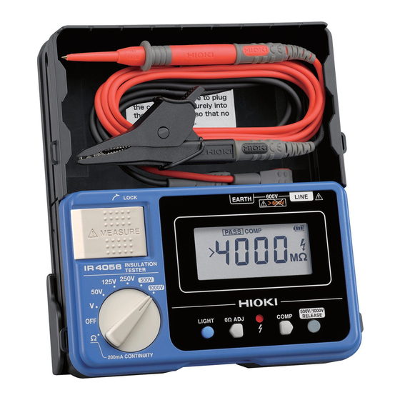
1.3 Names and Functions of Parts 1.3 Names and Functions of Parts *This figure is model IR4057. Front Panel Display: IR4057 p.11) IR4056 p.12) EARTH terminal Measure key LINE terminal Connect the black Press to measure Connect the red test lead. - Page 15 1.3 Names and Functions of Parts Display (IR4057) Bar graph Measured value Comparator judgment reference value or 1-minute value Indicates the remaining battery life as one of three levels. The battery mark outline will flash when the remaining battery life reaches 0, at which point the instrument will no longer perform measurement.
- Page 16 Turns on when the instrument is set to the 500 V range or the 1,000 V range. Pressing turns off the indicator and enables insulation measurement. Display (IR4056) Measured value or Comparator reference value Lights up when the criterion for the comparator function is indicated.
-
Page 17: Measurement Procedures
2.1 Measurement Preparations Measurement Procedures Chapter 2 2.1 Measurement Preparations Attach the strap. Insert the batteries. (p.41) Connect the test lead (connect the black test lead to the EARTH terminal, and the red test lead to the LINE terminal) Attaching the strap Pass the ring on both ends of the supplied strap through each of the four holes in the instrument. -
Page 18: Pre-Measurement Inspection
Exposed lation layer) inside the ent as you could cable exposed? receive an elec- tric shock. Contact your No Exposed authorized Hioki distributor or reseller for replacements. 1. Use the rotary selector to The following select Insulation Resis- issues may be tance. -
Page 19: Configuring The Comparator
2.3 Configuring the Comparator 2.3 Configuring the Comparator The instrument provides a comparator function that can be used with the insulation resistance and low resistance ranges. Use of the comparator function simplifies the process of obtaining a PASS/FAIL judgment. The comparator function generates PASS (good) and FAIL (defective) judgments depending on whether the measured value is greater than or less than a previous set value. -
Page 20: Setting The Comparator
“ ” to flash and displays the resistance value that will be used as the judgment reference. The IR4056 will display “ .” Press to select the judgment reference. If you do nothing for about 2 seconds after you select the desired judgment reference, the comparator will be set, and the “... - Page 21 2.3 Configuring the Comparator Valid judgment reference values Range Reference value Unit 0.01 0.02 0.03 0.04 0.05 50 V (Default setting: 1 MΩ) 125 V (Default setting: 1 MΩ) 250 V MΩ (Default setting: 1 MΩ) 500 V (Default setting: 1 MΩ) 1000 V (Default setting: 10 MΩ) 索引...
-
Page 22: Insulation Resistance Measurement
2.4 Insulation Resistance Measurement 2.4 Insulation Resistance Measurement The instrument is used to measure insulation resistance in the electric circuit or in the appliance in order to inspect the insulation performance. When measuring insulation resistance, you have to select the voltage applied to the object to be measured. -
Page 23: Lock Function
500 V or 1,000 V range. Releasing the lock Setting the rotary selector to the 500 V or 1,000 V range will cause (IR4057) or (IR4056) to light up, and will flash yellow. Flashing 索引... - Page 24 2.4 Insulation Resistance Measurement Press to turn off as well , disabling the lock. The display will also change to the measurement screen. The instrument will return to the state described in Step when 1 minute elapses after the last measurement or operation. Press to release the lock.
-
Page 25: Measuring Insulation Resistance
2.4 Insulation Resistance Measurement 2.4.2 Measuring Insulation Resistance Always turn off the breaker of the measurement line. Source (primary side) Load (secondary side) Ex. When measuring the insulation resistance between circuit and ground If the MEASURE key is in the raised position, push it down. -
Page 26: Displaying 1-Min. Values (Ir4057 Function)
2.4 Insulation Resistance Measurement The final measured value will be displayed along with , and discharge will start. When disappears, measurement is complete. • During measuring, do not selector over to the other function. • The instrument will return to the locked state when about 1 minute of no operation elapses during measurement in the 500 V and 1,000 V ranges. -
Page 27: Discharging Function
2.5 Discharging Function 2.5 Discharging Function When measuring an insulation resistance that contains a capacitance element, a charge proportional to the measurement voltage accumulates, and if undischarged could lead to an electric shock accident. Without removing the test leads from the item being measured, release the MEASURE key. -
Page 28: Voltage Measurement
2.6 Voltage Measurement 2.6 Voltage Measurement This instrument can measure the AC of commercial power. It is also useful to make sure the subject conductor is not live before measuring insulation resistance. • Test leads should only be connected to the secondary side of a breaker, so the breaker can prevent an accident if a short circuit occurs. - Page 29 2.6 Voltage Measurement Source (primary side) Caution: Do not press the EARTH MEASURE key. LINE Load (secondary side) Always connect the test lead to the secondary side of the breaker. Ex. When measuring the voltage between circuit and ground Use the rotary selector to select the V function. Connect the black test lead to the ground side of the object being measured.
-
Page 30: Low Resistance Measurement
2.7 Low Resistance Measurement 2.7 Low Resistance Measurement Do not measure under a live circuit condition. Before measurement, always perform zero adjustment to cancel the test leads’ wiring resistance and other potentially problematic quantities. Accurate measurement will not be possible if zero adjustment is not performed. Set the rotary selector to the Ω... - Page 31 2.7 Low Resistance Measurement The comparator function can be used during low resistance measurement. See: "2.3 Configuring the Comparator" (p.15) Ex. Checking the continuity of ground wiring If an additional operating circuit is connected in parallel to the circuit under measurement, the measurement error may occur due to the effects of impedance of the circuit connected in parallel or transient currents.
-
Page 32: Auto Power Save (Power-Saving Function)
2.8 Auto power save (power-saving function) 2.8 Auto power save (power-saving function) To avoid battery depletion, turn the rotary selector OFF after use (the Auto Power Save feature consumes a small amount of current). When the rotary selector is not at OFF, the power save function kicks in 10 minutes after the last time the MEASURE key is pressed. -
Page 33: Chapter 3 Specifications
Specifications Chapter 3 rdg. (reading or displayed value) The value currently being measured and indicated on the mea- suring instrument. dgt. (resolution) The smallest displayable unit on a digital measuring instrument, i.e., the input value that causes the digital display to show a "1" as the least-significant digit. -
Page 34: General Specifications
(Replacements) capacity type) Approx. 159W×177H×53D mm Dimensions (6.26”W×6.97”D×2.09”D)(excluding protrusions) IR4056: Approx. 600g (21.2 oz.) Mass IR4057: Approx. 640g (22.6 oz.) (including battery, excluding test lead) * The nominal circuit voltage refers to the nominal voltage of an electric distribution circuit that can be measured by this measuring instrument... -
Page 35: Measurement Functions
L9787 Test Lead..........1 Neck strap............1 Accessories Instruction manual ..........1 LR6 alkaline battery........... 4 L9787 Test Lead L9787-91 Breaker Pin L9788-10 Test Lead with Remote Switch (Red) Options L9788-11 Test Lead Set with Remote Switch L9788-90 Tip Pin L9788-92 Breaker Pin 9804-02 Magnetic Adapter EN61326 (EMC) - Page 36 Insulation Resistance Measurement Rated output 50 V 125 V 250 V 500 V 1000 V voltage (DC) Display range 1 MΩ 1 MΩ 1 MΩ 1 MΩ 1 MΩ Maximum indicated 1.000 MΩ 1.000 MΩ 1.000 MΩ 1.000 MΩ 1.000 MΩ value Resolution 0.001 MΩ...
- Page 37 600 VAC (10 s) protection (10 s) Display IR4057: Within 0.6 s (no update during response) update IR4056: Within 1.0 s (no update during response) interval Measurement terminal voltage characteristic Open-circuit 1 to 1.2 times of nominal output voltage voltage...
- Page 38 Resistance Measurement Open-circuit 4.0 to 6.9 V voltage Measuring 200 mA or more (at 6 Ω or less current ±3%rdg.±2dgt. Effect of (applicable to the operating temperature range temperature other than 18C to 28C.) Effect of supply ±3%rdg.±2dgt. and within allowance voltage Within 1 s (measurement terminal open →...
- Page 39 Voltage Measurement AC/DC automatic AC detected at 30 V or greater (50/60 Hz) detection range Effect of Measurement accuracy per 1°C × 0.1 temperature Overload 750 VAC (10 s), 750 VDC (10 s) protection Display update Within 1 s interval Within 1.2 s Response time (when input voltage is cycled from 0 V to 600 V)
-
Page 41: Maintenance And Service
• When sending the instrument for repair, remove the batteries and pack carefully to prevent damage in transit. Include cushioning material so the instrument cannot move within the package. Be sure to include details of the problem. Hioki cannot be responsible for damage that occurs during shipment. - Page 42 4.1 Troubleshooting Symptom Check Items The 500 V and 1,000 V ranges use double-action to prevent the inadvertent application of the measurement signal. Unable to perform measurement in → Press after setting the rotary selector to 500 V or 1,000 V range.
- Page 43 4.1 Troubleshooting Symptom Check Items The differences are due to the effects of the insulator’s polarity. * → Allow an adequate amount of time (about 1 hour to 1 day) to pass after the first measurement before repeating measurement. The effects of polarity increase as the insulation A different resistance increases.
- Page 44 4.1 Troubleshooting Error Displays and Remedies Display Description Remedy Verify that there is no broken connection in the test leads. Zero adjustment can be performed for readings of The instrument was unable up to 3 Ω. Ensure that the to perform zero wiring resistance is 3 Ω...
-
Page 45: Replacing Batteries Or Fuse
Fuse type: FF0.5AH/1000V (70 172 40.0.500: SIBA) (Very fast acting, arc extinction type, high rupturing capacity type) Fuses can be purchased from your Hioki distributor. • To avoid electric shock, turn off the rotary selector and disconnect the test leads from the object to be measured, before replacing the batteries or fuse. -
Page 46: Cleaning
4.3 Cleaning Back of the instrument Screw Battery cover batteries fuse Turn the rotary selector to OFF and remove the test lead from the instrument as a precaution. Loosen the central fastening screw at the back of the instrument and remove the battery cover. Replace all four batteries or the fuse. -
Page 47: Appendix
Appendix Appendix Measurement Principles 1. Insulation resistance measurement The measurement target’s insulation resistance Rx is calculated by applying a voltage V to the target, measuring the leak current I that flows to the target as a result, and dividing the voltage V by the leak current I. 2. - Page 48 Appendix Operation Uncertainty The operation uncertainty and the variations of measurement value for the respective Influence quantity approved by EN/ IEC61557 are as follows: Intrinsic Variation Operation uncertainty/ Insulation range Influence quantity resistance resistance Intrinsic Reference ±5%rdg. ±3%rdg.±2dgt. condition uncertainty Supply 4.5 V to 6.8 V ±4%rdg.
Need help?
Do you have a question about the IR4056 and is the answer not in the manual?
Questions and answers