Table of Contents
Advertisement
Quick Links
Advertisement
Table of Contents

Related Manuals for Hioki CLAMP ON LEAK HiTESTER 3283


Summary of Contents for Hioki CLAMP ON LEAK HiTESTER 3283
- Page 1 3283 CLAMP ON LEAK HiTESTER INSTRUCTION MANUAL...
-
Page 3: Table Of Contents
Contents Introduction Inspection Safety Notes Notes on Use Chapter Summary Chapter 1 Product Outline 1.1 Product Outline 1.2 Features 1.3 Parts and Functions Chapter 2 Measurement Procedure 2.1 Preparations 2.2 Leak Current Measurement A 2.3 Filter Function FILTER 2.4 Data Hold Function HOLD 2.5 Recording Function REC 2.6 Auto Power-Off Function... -
Page 5: Introduction
__________________________________________________ Introduction Thank you for purchasing the HIOKI "3283 CLAMP ON LEAK HiTESTER." To obtain maximum performance from the product, please read this manual first, and keep it handy for future reference. We have tried to bring this manual as close to perfection as we could achieve. -
Page 6: Safety Notes
__________________________________________________ Safety Notes DANGER This product is designed to conform to IEC 61010 Safety Standards, and has been thoroughly tested for safety prior to shipment. However, mishandling during use could result in injury or death, as well as damage to the product. - Page 7 __________________________________________________ Safety symbols symbol printed on the product indicates that the user should refer to a corresponding topic in the manual (marked with the symbol) before using the relevant function. In the manual, the symbol indicates particularly important information that the user should read before using the product.
- Page 8 __________________________________________________ Measurement categories (Overvoltage categories) This product complies with CAT III safety requirements. To ensure safe operation of measurement product, IEC 61010 establishes safety standards for various electrical environments, categorized as CAT I to CAT IV, and called measurement categories. These are defined as follows.
-
Page 9: Notes On Use
If you find any damage, contact your dealer or Hioki representative. When conductors being measured carry in excess of the safe voltage level (SELV-E) and... - Page 10 __________________________________________________ DANGER Do not use clamp testers on bare conductors. When the clamp sensor jaw is open, there is a risk of short-circuits and accidents that could result in injury or death. Use clamp testers only on power lines up to AC 300 V rms, to avoid short-circuits and accidents that could result in injury or death.
- Page 11 __________________________________________________ WARNING To avoid electric shock, do not allow the product to get wet, and do not use it when your hands are wet. To avoid electric shock when measuring live lines, wear appropriate protective gear, such as insulated rubber gloves, boots and a safety helmet.
- Page 12 __________________________________________________ CAUTION This is a precision instrument: do not clamp any foreign objects in the end of the clamp sensor, or insert anything in the clamp sensor gap. To avoid damage to the product, protect it from vibration or shock during transport and handling, and be especially careful to avoid dropping.
- Page 13 __________________________________________________ CAUTION Do not use the unit if the battery is exhausted (when the mark lights in the display area). Be sure to replace the exhausted battery with a new one. When replacing the battery, make sure that the metal battery snap fitting is firmly connected. If the metal fitting is loose, adjust it and recheck the connection.
- Page 14 __________________________________________________ For circuits which carry several superimposed NOTE currents, correct measurements may not be obtained. Accurate measurement may be impossible in the presence of strong magnetic fields, such as near transformers and high-current conductors, or in the presence of strong electromagnetic fields such as near radio transmitters.
-
Page 15: Chapter Summary
__________________________________________________ Chapter Summary This manual consists of the following chapters. "Introduction", "Safety Notes", "Notes on Use" describe precautions on use, overview, and features of this unit. Be sure to read them all. Next, check Chapter 1 to 3 and the unit to confirm your understanding of the function. - Page 16 __________________________________________________ _____________________________________________...
-
Page 17: Chapter 1 Product Outline
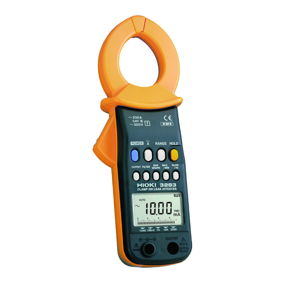
__________________________________________________ Chapter 1 Product Outline 1.1 Product Outline The 3283 CLAMP ON LEAK HiTESTER is designed for wide-range measurement on live circuits, from very small leak currents up to load currents of 200 amperes. The clamp part is made of material with high magnetic permeability, to minimize adverse effects caused by external magnetic fields, and to reduce tolerances due to the position of the... - Page 18 __________________________________________________ True rms indication The true rms conversion circuit delivers accurate results not affected by leak current distortion. Filtering The widespread use of switching power supplies and equipment incorporating inverter technology frequently causes harmonics to be superimposed in the leak current waveform. The filter in the 3283 allows two kinds of measurement, for leak current caused by insulation faults and for leak currents including...
- Page 19 __________________________________________________ Dual power supply design The unit can be powered using the optional 9445-02 AC adapter (SA10-0910N, SINO- AMERICAN), 9445-03 AC adapter (for EU) (SA10-0910G, SINO-AMERICAN), or from a battery. _____________________________________________ Chapter 1 Product Outline...
-
Page 20: Parts And Functions
__________________________________________________ 1.3 Parts and Functions Top and Side View _____________________________________________ Chapter 1 Product Outline... - Page 21 __________________________________________________ 1. Clamp sensor 2. Operation lever 3. Key switches 4. Display (LCD) 5. Output jack 6. AC adapter jack 7. Rear cover 8. Hand Strap _____________________________________________ Chapter 1 Product Outline...
- Page 22 __________________________________________________ AUTO Auto-range SLOW Update display once every 3 seconds Record function Maximum value Minimum value Average value = (maximum value + minimum value/2) 1 minute/segment (bar graph) hour 1 hour/segment (bar graph) HOLD Data hold function Auto power off function Waveform output (AC) is active Recording output (DC) is active FILTER Filter function is active...
-
Page 23: Chapter 2 Measurement Procedure
__________________________________________________ Chapter 2 Measurement Procedure 2.1 Preparations 1. Remove the rear cover and insert the battery. (Refer to "Chapter 3 Battery Replacement".) 2. Press the POWER key to turn the unit on. Verify that all segments of the display light up briefly. -
Page 24: Leak Current Measurement A
__________________________________________________ 2.2 Leak Current Measurement A 1. Press the A key. 2. Clamp the tester on the conductor, so that the conductor passes through the center of the clamp sensor. For measurement of grounded leads, clamp the tester on one lead only (see a). - Page 25 __________________________________________________ three-phase 3-lead clamp all three leads of the circuit circuits Load device E (PE) For measurement of single-phase 2-lead NOTE circuits, clamp both leads of the circuit. For measurement of three-phase 4-lead circuits, clamp all four leads of the circuit. If this is not possible, the measurement can also be carried out on the ground lead of the equipment.
- Page 26 __________________________________________________ 3. The effective value (RMS) of the leak current is shown on the digital display. The selected current range is shown at the bottom of the display. Do not input current that exceeds the NOTE maximum continuous input of the electric current range.
- Page 27 __________________________________________________ 【Checking for insulation faults】 Normally, for a E (PE) grounding installation of a transformer, the measurement will first be made to check for overall circuit leak current in the ground lead (a). Current changes can be used to diagnose the leak current condition. When leak current has been detected, the measurement should proceed from the power source towards the load, using overall...
- Page 28 __________________________________________________ 【Range switching】 Each push of the RANGE key switches the range in the order 10 mA → 100 mA → 1 A → 10 A → 200 A → AUTO. 【Changing the display characteristics SLOW】 If the indicated current value fluctuates rapidly and is hard to read, you can select a slower update rate (once every 3 seconds) by pressing the SLOW/Hz key.
- Page 29 __________________________________________________ 【Frequency (Hz) display】 1. While the display is switched to SLOW mode, press the SLOW/Hz key. 2. The frequency of the measured current is displayed. If there is no input, and input is lower than 30Hz, "----" is shown. Each push of the SLOW/Hz key cycles through the following modes: SLOW→Hz→RMS...
- Page 30 __________________________________________________ 【Load current measurement】 Be sure to clamp only one lead of the conductor. The frequency of special waveforms such as NOTE at the secondary side of an inverter may not be indicated correctly. Depending on the magnitude and frequency of the input current, resonances may be heard from the clamp jaw.
-
Page 31: Filter Function Filter
__________________________________________________ 2.3 Filter Function FILTER The widespread use of switching power supplies and equipment incorporating inverter technology can cause harmonics to be superimposed on the leak current waveform. 1. Press the FILTER key. The FILTER indication appears. The integrated low-pass filter is now active, cutting off unwanted higher-frequency components. -
Page 32: Data Hold Function Hold
__________________________________________________ 2.4 Data Hold Function HOLD This function allows freezing the display at any desired point for easy reading. 1. Press the HOLD key. The HOLD indication appears on the display and the digital display value is maintained. To cancel the data hold function, press the HOLD key again. - Page 33 __________________________________________________ 3. During measurement, the MAX/MIN key can be used to select the value that should be shown. MAX: Maximum value is shown. MIN: Minimum value is shown. AVE: Average value is shown = (maximum value + minimum value)/2 If none of the MAX, MIN, or AVE indicators is shown, the display shows the instantaneous value.
- Page 34 __________________________________________________ Momentary power loss and power surges NOTE cannot be detected. When the unit is turned off, accumulated data are lost. The maximum recording duration depends on the remaining battery capacity. The lowest possible frequency that can be displayed is 30.0 Hz. If the measurement object was clamped after activating the recording function, the minimum value is always zero.
- Page 35 __________________________________________________ 【Bar graph indication BAR GRAPH】 The bar graph display can be changed. It is also possible to display the current range, effective (rms) value of the measured current, and the elapsed time (hours and minutes). 1. Press the BAR GRAPH key. 2.
- Page 36 __________________________________________________ When the segments left of a flashing segment remain on: the number of "on" segments represents the elapsed time (0 to 29). The illustration below shows when 20 minutes have elapsed: When the segments right of a flashing segment remain on: the number of "off"...
-
Page 37: Auto Power-Off Function Aps
__________________________________________________ 2.6 Auto Power-Off Function When is displayed, the auto power-off function is active. If no key is pressed for about 10 minutes, the unit turns itself off automatically. Immediately before turning off, the indication flashes and a beep tone is heard for about 30 seconds. -
Page 38: Fast Mode
__________________________________________________ 2.9 Fast Mode The display update rate can be set to 4 times per second. This is useful for example to measure load currents with frequent variations and similar applications. 1. Press the A key twice in succession. The indication "F" is briefly shown, and the unit switches to fast mode. -
Page 39: Output Function Output
__________________________________________________ 2.10 Output Function OUTPUT The output type is indicated by the REC (recording output, DC) or (waveform output, AC) indication. An output signal corresponding to the measured value can be obtained from the unit. The output voltage (AC/DC) normally is 1 V for the full- scale count (1000). - Page 40 __________________________________________________ 【Output rate】 (waveform output : AC) REC (recording output : DC) Current Crest Output rate Accuracy Range Factor 10 mA AC/DC 1 V/10 mA 100 mA AC/DC 1 V/100 mA AC/DC: 2.5 or less 1 A AC/DC 1 V/1 A 3.0% rdg.
- Page 41 __________________________________________________ To use the output function, be sure to push the NOTE OUTPUT key so that either REC or shown. There is no frequency output function. The filter function can be used to cut unwanted high- frequency components. If the OUTPUT key is pressed while auto- range (AUTO) is enabled, the range is fixed at the current setting (AUTO indication goes out).
- Page 42 __________________________________________________ _____________________________________________ Chapter 2 Measurement Procedure...
-
Page 43: Chapter 3 Battery Replacement
__________________________________________________ Chapter 3 Battery Replacement CAUTION Do not fix the back casing screws too tightly. The torque about 0.5N・m is recommended. 1. Remove the two fastening screws of the rear cover, using a Phillips screwdriver. 2. Remove the rear cover. 3. - Page 44 __________________________________________________ _____________________________________________ Chapter 3 Battery Replacement...
-
Page 45: Chapter 4 Attaching The Hand Strap
__________________________________________________ Chapter 4 Attaching the Hand Strap Explains how to attach the hand strap, for easy handling of the unit in the field. _____________________________________________ Chapter 4 Attaching the Hand Strap... - Page 46 __________________________________________________ _____________________________________________ Chapter 4 Attaching the Hand Strap...
-
Page 47: Chapter 5 Specifications
__________________________________________________ Chapter 5 Specifications 5.1 Measurement Specifications Temperature and humidity for guaranteed accuracy: 23 (73 9), 80% RH or less Guaranteed accuracy period:1 year, or opening and closing of the Clamp Sensor 10,000 times, whichever comes first _____________________________________________ Chapter 5 Specifications... -
Page 48: Ac Current Arms(True Rms Indication)
__________________________________________________ 5.1.1 AC current Arms(true rms indication) Current Range Accuracy Maximum (Accuracy Resolution (NOTE) permitted Range) (%rdg.+dgt.) current 10 mA 0.01 mA (1.00 to 10.00 mA) 45 to 66 Hz: 100 mA 20 Arms 0.1 mA (1.0%+5) (10.0 to 100.0 mA) 40 to 45 continuous 66 to 2 kHz:... -
Page 49: Frequency Hz
__________________________________________________ Effect of conductor within 0.1% (in any direction from clamp sensor position center) 100 A MAX: within 0.5% Effect of external AC 400 A/m corresponds to 5 mA, max. 7.5 mA magnetic fields Maximum rated max. 300 V rms AC (insulated conductor) voltage to earth Frequency [Hz]... -
Page 50: General Specifications
__________________________________________________ 5.2 General Specifications Functions Recording Maximum (MAX), minimum (MIN), average (AVE) value display selectable for AC current and frequency measurement Data hold Data hold function Automatic shutdown after 10.5 1 Auto power-off minutes. Beep tone warning. Extension and disabling possible. Battery low voltage When the battery voltage falls below a certain level, the function shuts... - Page 51 __________________________________________________ Data hold indication HOLD Auto power-off indication Filter function Cutoff frequency 180 Hz 30 Hz (-3 dB) Display update rate Digital indication NORMAL: 500 ms 25 ms (approx. 2 times/second) SLOW : 3 s 0.15 s (approx. 1 time/3seconds) FAST : 250 ms 12.5 ms (approx.
- Page 52 __________________________________________________ Circuit dynamic 2.5 max. (1.5 for 200 A range) characteristics (crest factor) Withstand voltage Chassis - clamp core: 3536 Vrms AC for 15 seconds Insulation Clamp core - circuitry: 630 kilohms min. resistance Location for use Indoor, altitude up to 2000 m Safety: EN 61010-1:2001 Applicable Voltage input: Pollution level...
- Page 53 __________________________________________________ Power source One 6F22 (006P) 9 V battery or 9445-02 AC ADAPTER (SA10-0910N, SINO-AMERICAN) or 9445-03 AC ADAPTER (EU) (SA10- 0910G, SINO-AMERICAN) (option) Maximum power 100 mVA consumption Battery life approx. 40 hours (continuous, no load) External approx. 62W x 225H x 39D mm dimensions Mass approx.
- Page 54 __________________________________________________ _____________________________________________ Chapter 5 Specifications...
-
Page 55: Chapter 6 Troubleshooting
__________________________________________________ Chapter 6 Troubleshooting If the unit seems not to be working normally, check the following points first before requesting service. Problem Cause Action Problems related to the power supply Power will not The battery may Replace it with a turn on be low or new battery... - Page 56 __________________________________________________ Problem Cause Action Problems related to display An error Internal memory Request repair between E.001 may be and E.005 or damaged E.100 is displayed. Problems related to the clamp sensor The clamp When large Reclamp the sensor current or high- conductor.
- Page 57 __________________________________________________ Problem Cause Action Problems related to output function The output The 200 A range Check the rate differs is used electric current from the range. Unlike specification other ranges, the The output is full scale of the too low 200 A range is 2 V/fs The input...
- Page 58 __________________________________________________ _____________________________________________ Chapter 6 Troubleshooting...
-
Page 59: Chapter 7 Service
The minimum stocking period for replacement parts is five years after end of production. For information regarding service, please contact your dealer or the nearest HIOKI representative. If the unit is not functioning properly, check the battery. If a problem is found, contact your dealer or HIOKI representative. - Page 60 __________________________________________________ _____________________________________________ Chapter 7 Service...
- Page 63 HIOKI 3283 CLAMP ON LEAK HiTESTER Instruction Manual Publication date: September 2006 Revised edition 13 Edited and published by HIOKI E.E. CORPORATION Technical Sales Support Section All inquiries to International Sales and Marketing Department 81 Koizumi, Ueda, Nagano, 386-1192, Japan TEL: +81-268-28-0562 / FAX: +81-268-28-0568 E-mail: os-com@hioki.co.jp...
- Page 64 HEAD OFFICE 81 Koizumi, Ueda, Nagano 386-1192, Japan TEL +81-268-28-0562 / FAX +81-268-28-0568 E-mail: os-com@hioki.co.jp/ URL http://www.hioki.co.jp/ HIOKI USA CORPORATION 6 Corporate Drive, Cranbury, NJ 08512, USA TEL +1-609-409-9109 / FAX +1-609-409-9108 3283A980-13 06-09H Printed on recycled paper...
Need help?
Do you have a question about the CLAMP ON LEAK HiTESTER 3283 and is the answer not in the manual?
Questions and answers