Table of Contents
Advertisement
Available languages
Available languages
Quick Links
PRZETWORNIK PROGRAMOWALNY
NAPIĘCIA I PRĄDU STAŁEGO
PROGRAMMABLE TRANSDUCER
OF DC CURRENT AND DC VOLTAGE SIGNALS
P20H
INSTRUKCJA OBSŁUGI SZYBKI START
PL
USER'S MANUAL QUICK START
EN
Zeskanuj mnie
Zeskanuj kod
Scan the code
Pełna wersja instrukcji dostępna na
Full version of user's manual available at
www.lumel.com.pl
Advertisement
Table of Contents

Related Manuals for Lumel P20H Series


Summary of Contents for Lumel P20H Series
- Page 1 NAPIĘCIA I PRĄDU STAŁEGO PROGRAMMABLE TRANSDUCER OF DC CURRENT AND DC VOLTAGE SIGNALS P20H INSTRUKCJA OBSŁUGI SZYBKI START USER’S MANUAL QUICK START Zeskanuj mnie Zeskanuj kod Scan the code Pełna wersja instrukcji dostępna na Full version of user’s manual available at www.lumel.com.pl...
- Page 2 1. BEZPIECZEÑSTWO U¯YTKOWANIA W zakresie bezpieczeństwa użytkowania przetwornik odpowiada wymaganiom normy PN-EN 61010-1. Znaczenie symbolu: - Uwaga, grozi niebezpieczeństwo Uwagi dotyczące bezpieczeństwa · Montażu i instalacji połączeń elektrycznych powinna dokonać osoba z uprawnieniami do montażu urządzeń elektrycznych. · Przed włączeniem przetwornika należy sprawdzić poprawność połączeń.
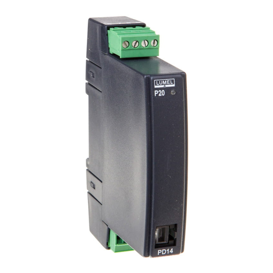
- Page 3 Rys 1. Gabaryty i sposób mocowania przetwornika 2.2. Schematy podłączeñ zewnêtrznych Przetwornik posiada listwę rozłączną z zaciskami śrubowymi, które umożliwiają przyłączenie przewodów zewnętrznych zasilania i wyjścia o przekroju do 2,5 mm . Podłączenia sygnałów wejściowych należy wykonać przewodami o maksymalnej średnicy 1,5 mm do zacisków śrubowych nierozłącznych.
- Page 4 3. OBS£UGA Po włączeniu zasilania przetwornika, dioda stanu pracy powinna się zaświecić na chwilę na czerwono, następnie na zielono. Dioda stanu pracy przetwornika: - dioda stanu świeci się na zielono – normalna praca; - dioda stanu świeci się na czerwono – niewłaściwe parametry pracy;...
-
Page 5: Dane Techniczne
3.1. Konfiguracja przetwornika za pomocą programu eCon Do konfiguracji przetworników P20H przeznaczone jest bezpłatne oprogramowanie eCon dostępne na stronie www.lumel.com.pl. W wykonaniu z interfejsem RS-485, przetwornik możne być konfiguro- wany bezpośrednio przez interfejs. Przy konfiguracji przetwornika po- przez programator PD14, należy odłączyć interfejs RS-485. - Page 6 Interfejs szeregowy RS-485: adres 1...247; tryb: 8N2, 8E1, 8O1, 8N1 prędkość: 4.8, 9.6, 19.2 kbit/s; protokół transmisji: Modbus RTU; czas odpowiedzi: 200 ms Błąd podstawowy przetwarzania ±0,2% zakresu Błędy dodatkowe w znamionowych warunkach użytkowania: od zmian temperatury otoczenia (50% błędu podstawowego/10 K) Przeciążalność...
- Page 7 5. KOD WYKONAÑ Kod wykonań przetwornika P20H Tablica 2 PRZETWORNIK P20H - Sygnał wejściowy: +/- 100 V d.c..........1 +/- 250 V d.c..........2 +/- 400 V d.c..........3 +/- 1 A d.c..........4 +/- 5 A d.c..........5 0...100 V d.c.
-
Page 8: Basic Requirements, Operational Safety
1. BASIC REQUIREMENTS, OPERATIONAL SAFETY In the safety service scope, the transducer meets the requirements of the EN 61010-1 standard. Observations concerning the operational safety: · All operations concerning transport, installation, and commissioning as well as maintenance, must be carried out by qualified, skilled personnel, and national regulations for the prevention of accidents must be observed. -
Page 9: Installation
2. INSTALLATION 2.1. Fixing Way P20H transducers are destined to be fixed on a 35 mm rail acc. to EN 60715 standard. Overall dimensions and the fixing way are presented on the fig. 1. Fig. 1. Overall dimensions and fixing way of the P20H transducer 2.2. - Page 10 3. SERVICE After switching the transducer on, the work state diode should light in red for a moment, next it should light in green. Diode of the transducer work state: - the state diode lights in green – normal work, - the state diode lights in red –...
-
Page 11: Technical Data
(Out-u) for values above the upper input overflow (In-u) – Values are presented in the table 3 (see full version of user’s manual, avilable at www.lumel.com.pl). 3.1. Transducer Configuration by Means of the eCon Program The free delivered eCon program, available in our www.lumel.com.pl... - Page 12 Basic conversion error: ±0.2% of the range Additional errors in rated operating conditions: - from ambient temperature changes (50% of the intrinsic error/10 K) Sustained overload: 150% Un (in. 400 V, ± 400 V),120% Un (other in.),120% In Short duration overload (1 s): voltage input 2 Un (<1000 V); current input 10 In Rated operating conditions: - supply voltage: 85..253 V a.c.
-
Page 13: Ordering Codes
5. ORDERING CODES Table 2. TRANSDUCER P20H - Input signal: +/- 100 V d.c..........1 +/- 250 V d.c..........2 +/- 400 V d.c..........3 +/- 1 A d.c..........4 +/- 5 A d.c..........5 0...100 V d.c. - Page 14 schematy podłączeń electrical connections Rys. 2. Podłączenia elektryczne wejœæ przetwornika P20H: a) prądowe b) napiêciowe Fig. 2. Electrical connections of P20H transducer inputs. a) voltage b) current...
- Page 15 Rys. 3. Podłączenia elektryczne zasilania i wyjœcia P20H: a) z wyjœciem analogowym b) z interfejsem Fig. 3. Electrical connections of the P20U transducer supply and output:a) with analog output, b) with RS-485 interface...
- Page 16 LUMEL S.A. ul. Sulechowska 1, 65-022 Zielona Góra, Poland tel.: +48 68 45 75 100, fax +48 68 45 75 508 www.lumel.com.pl Informacja techniczna: tel.: (68) 45 75 306, 45 75 180, 45 75 260 e-mail: sprzedaz@lumel.com.pl Realizacja zamówień: tel.: (68) 45 75 207, 45 75 209, 45 75 218, 45 75 341 fax.: (68) 32 55 650...
Need help?
Do you have a question about the P20H Series and is the answer not in the manual?
Questions and answers