Table of Contents
Advertisement
Quick Links
Advertisement
Table of Contents

Related Manuals for Lumel P20G series


Summary of Contents for Lumel P20G series
- Page 1 SEPARATOR P20G TYPE USER’S MANUAL...
-
Page 3: Table Of Contents
Contents 1. APPLICATION ................5 2. SEPARATOR SET ..............5 3. OPERATIONAL SAFETY ............6 4. FITTING ..................7 4.1. Fixing Way ................7 4.2. External Connection Diagrams ..........8 5. SERVICE ..................9 6. TECHNICAL DATA OF THE P20G SEPARATOR ....10 7. -
Page 5: Application
1. APPLICATION The P20G separator is destined to realize the galvanic separation of current and voltage analog signals. The output signal is galvanically isolated from the input signal and the supply. One can also obtain in the separator the linear conversion of one kind of signal led to its input into a standard output signal of another kind. -
Page 6: Operational Safety
3. OPERATIONAL SAFETY In the safety service scope, the transducer meets to requirements of the EN 61010-1 standard. Observations Concerning the Operational Safety · All operations concerning transport, installation, and commissioning as well as maintenance, must be carried out by qualified, skilled personnel, and national regulations for the prevention of accidents must be observed. -
Page 7: Fitting
4. INSTALLATION 4.1. Fitting Way P20G transducers are designed to be mounted on a 35 mm rail accor- ding to EN 60715. Overall dimensions and fitting way are shown on the fig. 1. Fig. 1 Overall dimensions and the separator fitting way. Separators should be mounted on the rail in direct contact with another devices that emit heat (eg transducer P20G). -
Page 8: External Connection Diagrams
4.2. External Connection Diagrams The separator has two terminal strip sockets, which two plugs with ter- minal screws are connected to and enable the connection of external wires with 2.5 mm cross-section (terminals 6-9) and 1.5 mm cross- section (terminals 1-5). For the connection of signal terminals, one must use shielded wires. -
Page 9: Service
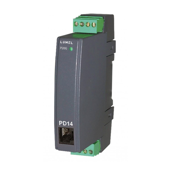
Fig. 3. View of the P20G separator. Confirmation of the separator’s communication with PD14 programmer is indicated by the status diode which turns off for short period of time. To configure P20G separator is designed LPCon software available on the web site: www.lumel.com.pl/. -
Page 10: Technical Data Of The P20G Separator
6. TECHNICAL DATA Basic parameters: – analog output galvanicaly isolated: - current (max. range) - 20...20 mA - voltage (max. range) -10...10 V - load resistance of the current output £ 500 W - load resistance of the voltage output ³ 500 W –... - Page 11 Short duration overload /3 s Ensured protection grade acc. to EN 60529: - casing IP 40 - from terminal side IP 20 Dimensions 22.5 ´ 100 ´ 120 mm 0.125 kg Weight Fitting on a 35 mm DIN rail, acc.to EN 60715 Electromagnetic Compatibility: - noise immunity EN 61000-6-2...
-
Page 12: Execution Codes
7. ORDER CODES Order codes of the P20G separator Table 2 SEPARATOR P20G - XX XX Kind of programmed input: see table 3 ..........XX Kind of programmed output: see table 3 ............XX Supply: 85...253 V a.c./d.c............1 20...85 V d.c., 20...65 V a.c........2 Version: standard ................ - Page 13 Coding of input and output of the P20G separator Table 3 Range Input code Output code 0...1 V 0...5 V 0...10 V ± 1 V ± 5 V ± 10 V 0...5 mA 0...20 mA ± 5 mA ± 20 mA 4...20 mA Custom-made execution Conversion class >...
-
Page 14: Service And Maintenance
8. MAINTENANCE AND GUARANTEE The P20G separator does not require any periodical maintenance. In case of some incorrect operations: From the Shipping During the Period Given in the Annexed Guarantee Card: One should return the separator to the Manufacturer’s Quality Inspection Dept. - Page 16 P20G-09A “LUMEL” S.A. ul. Słubicka 1 65-127 Zielona Góra - Poland Tel.: (48-68) 45 75 100 (exchange) Fax: (48-68) 45 75 508 Export Department: e-mail: lumel@lumel.com.pl http://www.lumel.com.pl Tel.: (48-68) 45 75 139 or 305 Fax: (48-68) 325 40 91 e-mail: export@lumel.com.pl...
Need help?
Do you have a question about the P20G series and is the answer not in the manual?
Questions and answers