
Related Manuals for OutBack Power ProHarvest PRO208-5k75


Summary of Contents for OutBack Power ProHarvest PRO208-5k75
- Page 1 ProHarvest PRO208-5k75 (HiQ TS208-5k75) Inverter System Installation & Safety Manual...
- Page 2 ProHarvest, the ProHarvest logo, the phrase “ProHarvest by Outback Power”, and OutBack Power are trademarks owned and used by OutBack Power Technologies, Inc. HiQ, the HiQ logo, and TrueString are trademarks owned and used by HiQ Solar, Inc. These trademarks may be registered in the United States and other countries.
-
Page 3: Table Of Contents
Table of Contents Table of Contents ..........................3 Audience ............................ 5 Safety ............................5 2.1. Symbols Used .............................. 5 2.2. General Safety Provisions, Warnings, and Precautions ................6 Introduction ..........................7 3.1. System Overview ............................7 ProHarvest 208V Inverter ........................8 Communications Gateway ........................ - Page 4 PRO208V-5k75 Installation and Safety Manual System Firmware Updates ........................ 29 Gateway Access Inside a Local Network ................... 30 Accessing the Gateway from Outside the Local Network — LAN-side configuration ....... 31 Accessing the Gateway from Outside the Local Network – WAN-side configuration ....... 33 Troubleshooting ........................
-
Page 5: Audience
PRO208V-5k75 Installation and Safety Manual Audience These instructions are for use by qualified electricians or other personnel. Qualified personnel must meet all local and governmental code requirements for licensing and training for the installation of 3-phase electrical power systems with AC and DC voltage up to 1000 volts. They must also be familiar with communication networks. -
Page 6: General Safety Provisions, Warnings, And Precautions
PRO208V-5k75 Installation and Safety Manual General Safety Provisions, Warnings, and Precautions 2.2. Connection of the system must be to a 3-phase AC source which is 208 Vac nominal only. The ProHarvest 208V inverter is provided with DC circuit protection in accordance with the requirements for ungrounded systems as outlined in NEC 690.35(C). -
Page 7: Introduction
PRO208V-5k75 Installation and Safety Manual Introduction This instruction manual covers the ProHarvest 208V inverter system. A summary of features and functions is shown in the table. Item Inverter Grid voltage 208 Vac, Wye configuration Nominal power 5.75 kW Maximum Power Point Tracking, MPPT Per individual string Monitoring Per individual string... -
Page 8: Proharvest 208V Inverter
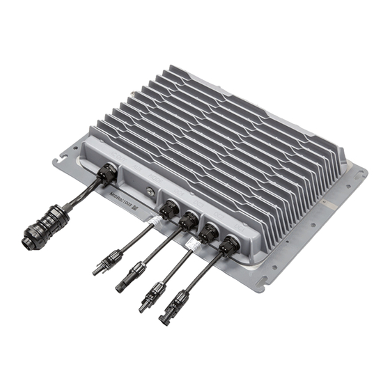
PRO208V-5k75 Installation and Safety Manual ProHarvest 208V Inverter One inverter connects to up to two strings of PV modules, and in turn to the 3-phase, 208 Vac compatible utility connection on the installation site. The ProHarvest 208V inverter is shown in Figure 2. It is a non-isolated inverter for use with ungrounded DC systems. -
Page 9: System Ordering & Part Number Identification
PRO208V-5k75 Installation and Safety Manual System Ordering & Part Number Identification A typical 5.75 kW system consists of: 1 ProHarvest 208V inverter 1 Communications Gateway which can be used with multiple inverters. Inverter Item Part Number Description Inverter, 5.75 kW, 208 Vac ProHarvest: Inverter with MC4-compatible connectors (1 each). - Page 10 PRO208V-5k75 Installation and Safety Manual Communications Gateway Item Part Number Description Communications Gateway ProHarvest: GW-A Communications Gateway 120 Vac (1 each). Includes Ethernet Cable (1 each), memory card for logging PROGW-A-120 and storage of results, and 120 Vac power cable. (HiQ: GW-A-120) Memory Card MCRD-A...
-
Page 11: Design Guidelines
PRO208V-5k75 Installation and Safety Manual Design Guidelines DC Stacking Ratio 5.1. The ratio of PV module STC power rating to inverter output power rating is often referred to as “Stacking Ratio.” Most PV installations are designed for a stacking ratio greater than 1, and less than 1.5. However, the only real limitation on stacking ratio for the inverter is the voltage and current limitations of the string inputs. -
Page 12: Inverter Placement
PRO208V-5k75 Installation and Safety Manual Inverter Placement The ProHarvest 208V inverter is NEMA6 rated and may be placed almost anywhere. Cooling is most efficient if the unit is mounted vertically in the shade, bolted to racking and with the connectors pointing downwards. However, any orientation is acceptable. -
Page 13: Grounding
PRO208V-5k75 Installation and Safety Manual Grounding The metal enclosure of the inverter must be grounded according to NEC 690.43. Equipment ground is provided through the AC connection. Optionally, grounding may be achieved also through attaching an Equipment Ground Conductor (EGC) to a lay-in lug (not provided) attached to the chassis as shown in Figure 7. -
Page 14: Installation
PRO208V-5k75 Installation and Safety Manual Installation The ProHarvest 208V inverter employs industry standard connection methods. These include locking interconnects for PV module attachment, and standard 5-lead, 3-phase AC wiring compatibility. Careful adherence to these instructions is required. Cautions 6.1. Make certain to follow all instructions. CAUTION: Hazard to Equipment The system must be connected to 208 Vac 3-phase wye 5-wire only. -
Page 15: Connection Outline
PRO208V-5k75 Installation and Safety Manual Connection Outline 6.2. Connection occurs in the following order: 1. Connect an equipment ground to the inverter. This should always be done first. 2. Connect the inverter to the grid. 3. Connect the Communications Gateway to the same 208 Vac circuit as the inverter and the network. 4. - Page 16 PRO208V-5k75 Installation and Safety Manual (b) Mate the male and female AC Connection connector to connect the inverter to the AC system. Use the AC tool to disconnect the male and female connectors. Follow steps 1 through 3 in the Disconnection section of Figure 11.
- Page 17 PRO208V-5k75 Installation and Safety Manual (b) Connect power to the Gateway using the appropriate AC cable (Figure 13). Ethernet may also be connected at this stage. Figure 13: Making Gateway connections AC Connection Ethernet Connection (optional) (c) Turn on power to the inverter. On the Gateway screen, select the Inverters tab A at the top of the screen if the unit is not already on that tab.
- Page 18 PRO208V-5k75 Installation and Safety Manual 5. Turn on the AC source. This starts a 5-minute timer. When it expires, each inverter will perform a self-test and then begin generating. During the wait period, the inverter button will be solid green. (See Table 2 on page 20.) This does not apply if the system is in the Off + Locked state.
-
Page 19: More Detailed Installation Information
PRO208V-5k75 Installation and Safety Manual More Detailed Installation Information 6.4. Meanings of Buttons & Indicators While most installations will use a Communications Gateway to control and report, it is not mandatory. The inverter can be controlled using the button, as illustrated in Table 1. A brief press-and-release of the button counts as a button-push in the guide below. -
Page 20: Manufacturing Date
PRO208V-5k75 Installation and Safety Manual Inverter Indicator State Meaning Powered up • Not generating • Solid No faults • Power-on self-test • (will take <1 minute) Left-right flash Powered up • Generating, no faults • Green Chaser Faulted • Example: arc has been detected •... -
Page 21: Gateway Information
PRO208V-5k75 Installation and Safety Manual Gateway Information 6.5. This section covers common tasks and features associated with the Gateway. Array Summary Screen Diagnostics Pressing the <Array> tab A brings up the Array Summary screen. This screen has four diagnostic indicators that are normally shaded green as shown in Table 3. -
Page 22: Methods Of Accessing System Information
PRO208V-5k75 Installation and Safety Manual Methods of Accessing System Information An overview of ways to access LOCAL data is shown in Figure 21. ProHarvest Database The Gateway gathers data Gateway from inverters over a connected power line. The Gateway Power line displays information on its touch screen. - Page 23 PRO208V-5k75 Installation and Safety Manual Button State Meaning Initial state. Once pressed, a dark blue color indicates the Gateway is in the process of discovering inverters. It will return to the initial state with an empty serial number list if no inverters are found. A dark red color indicates an error was found.
-
Page 24: Gateway Touch Screen Menu Structure
PRO208V-5k75 Installation and Safety Manual Gateway Touch Screen Menu Structure The following menu tree shows how different screens and functions are related and accessed. Setup Update AC Health Inverters Strings DC Health Diagnostic Detail Info Array Network Unlikely to need in normal use Clock Gateway... -
Page 25: Gateway Web Page Menu Structure
PRO208V-5k75 Installation and Safety Manual Gateway Web Page Menu Structure Overall Main Navigation Array (See next page) Menu (See A) (See B) Listed Inverter Summary for each inverter Figure 25: Array page and main inverter navigation 900-0203-01-00 Rev B... -
Page 26: Show Or Hide Web Page Controls
PRO208V-5k75 Installation and Safety Manual Figure 26: Gateway summary page (primarily for service use) Show or Hide Web Page Controls A valuable feature of the system is the ability to view and control the system from a smartphone when local computer network settings allow (see Section 6.5.11 on page 30). -
Page 27: Arc Detection
PRO208V-5k75 Installation and Safety Manual Arc Detection These products meet the requirements of NEC 690.11. If a fault occurs, the inverter will shut itself down. It will also indicate a fault with rapid red flashes of the inverter button. The web page and Gateway will also show system fault flags. -
Page 28: Utility Protective Function - Adjustable Limits
PRO208V-5k75 Installation and Safety Manual Utility Protective Function – Adjustable Limits The ProHarvest 208V inverter system is capable of operating beyond normal AC grid ranges when required to do so by the operating utility company. Changes in this area must only be carried out with the express written permission of the utility company, only setting values specified by the utility company. -
Page 29: System Firmware Updates
PRO208V-5k75 Installation and Safety Manual System Firmware Updates System firmware is occasionally updated to add features and enhance reliability even further. Firmware updates may be accomplished through a network connection or using a memory card physically inserted into the card slot on the Gateway. Updates may be controlled through the Gateway touch screen or the Gateway web page. -
Page 30: Gateway Access Inside A Local Network
PRO208V-5k75 Installation and Safety Manual Gateway Access Inside a Local Network The following sections may be useful for a company’s IT department. Note that the Gateway’s default state is to be in DHCP mode. This is the easiest mode for local access inside a network. -
Page 31: Accessing The Gateway From Outside The Local Network - Lan-Side Configuration
PRO208V-5k75 Installation and Safety Manual Accessing the Gateway from Outside the Local Network — LAN-side configuration DHCP has a lease time after which it requests renewal. This is problematic if it ends up with a different IP address. A method must be used to make the IP address stay fixed. These methods include: Keep the Gateway in DHCP mode but force the router to allocate the same IP address each time. - Page 32 PRO208V-5k75 Installation and Safety Manual Figure 33: Assigning an IP address outside the router’s DHCP reservation range Having decided upon an IP address, the next step is to configure the Gateway. On the touch screen of the Communications Gateway, select the Gateway tab, then press the <Network>...
-
Page 33: Accessing The Gateway From Outside The Local Network - Wan-Side Configuration
PRO208V-5k75 Installation and Safety Manual Figure 34: Network Setting screen on the Gateway The DHCP check box indicates current status. It also allows parameters to be changed if DHCP is unchecked. When unchecked, the box looks like this: Touching on one of the fields below the check box will activate it and allow changes to be made using the on-screen keypad. - Page 34 PRO208V-5k75 Installation and Safety Manual Figure 35: Port forwarding screen on the example Cisco router Press the <Save Settings> button on the router page or else changes will be lost. Note that not all routers offer port reassignment as described here. However, having different external port numbers is not strictly necessary;...
-
Page 35: Troubleshooting
PRO208V-5k75 Installation and Safety Manual Troubleshooting The primary troubleshooting method is to use the Communications Gateway for indications of a problem. The Gateway can be viewed using the touch screen interface on the device, or accessing it using a web browser. Assuming the issue is not with communications, browser access has the advantage that a mobile device such as a phone can be used while physically on the roof. -
Page 36: If This Issue Was Present, It Would Look Like These Symptoms
PRO208V-5k75 Installation and Safety Manual If this issue was present, it would look like these symptoms 7.2. Letters next to individual faults (such as D) refer to possible issues listed on page If this fault occurred, these symptoms would Gateway Touch Web Interface Inverter be present …. -
Page 37: If These Symptoms Occur, It Could Be One Of These Causes
PRO208V-5k75 Installation and Safety Manual If these symptoms occur, it could be one of these causes 7.3. Letters next to individual faults (such as D) refer to possible issues listed on page 35. Symptoms Possible Causes Inverter Gateway Touch Button Screen Interface Indicator... -
Page 38: Notes On Selected Issues
PRO208V-5k75 Installation and Safety Manual Notes on Selected Issues 7.4. Inverter indicator button Inverter Button Indicator States If there is power to the inverter, the indicator on the inverter button will be indicating something. As described earlier, these have the following meanings and operations: Inverter Button Push Button Indication... -
Page 39: Other Issues
PRO208V-5k75 Installation and Safety Manual Inverter Indicator State Meaning Powered up • Not generating • Solid No faults • Power-on self-test • (will take <1 minute) Left-right flash Powered up • Generating, no faults • Green Chaser Faulted • Example: “arc has been detected” •... -
Page 40: (B) Gateway Memory Card Issues
PRO208V-5k75 Installation and Safety Manual (B) Gateway Memory Card Issues No memory card ii) Memory card not fully engaged iii) Memory card not formatted as FAT32 Logging of long-term performance data is saved to the memory card that was supplied with the Gateway. Note that the card is No card not required for the system to operate, only to retain historical information. -
Page 41: (E) Inverter Installation Issues
PRO208V-5k75 Installation and Safety Manual The inverter automatically senses the phases connected to it. When wiring the system to the utility grid it does not matter which of the red, blue or orange wires are connected to which phase. However, a fault will appear if the neutral (white or grey) wire is connected to one of the phases. -
Page 42: Specifications
PRO208V-5k75 Installation and Safety Manual Specifications Power System Specifications 8.1. Inverter Specifications DC Input (2 identical inputs) Maximum open circuit voltage per String, V 1,000 Vdc Full power MPPT range, per string 325 to 525 Vdc PV start voltage 200 Vdc DC allowable stacking ratio (total, 2 inputs combined) Must not exceed 8.9 under any circumstances DC maximum input current, per DC input... -
Page 43: Communications Gateway Specifications
PRO208V-5k75 Installation and Safety Manual AC synchronization in-rush current Maximum output Fault current 16 A, 0.5 ms and duration AC minimum wire gauge for the 12 AWG grid connection AC disconnect means The AC connector has been evaluated and approved for use as the load-break disconnect required by the NEC Other Specifications Peak efficiency... -
Page 44: System Ul 1741 Certificates
PRO208V-5k75 Installation and Safety Manual System UL 1741 Certificates 8.3. 900-0203-01-00 Rev B... - Page 45 PRO208V-5k75 Installation and Safety Manual 900-0203-01-00 Rev B...
-
Page 46: Unit Rating Label
PRO208V-5k75 Installation and Safety Manual Unit Rating Label 8.4. One of the following labels appears on the back of the unit baseplate. Physical Dimensions & Drilling Guides 8.5. ProHarvest 208V Inverter 267 mm 267 mm (10 ½”) 10 ½“ 76 mm 76 mm (3”) 3“... - Page 47 PRO208V-5k75 Installation and Safety Manual 475 mm (18 ¾”) 238 mm (9 ⅜”) 12.6 mm (½”) 12.6 mm (½”) ProHarvest Inverter Front 450 mm (17 ¾”) 17¾” 450 mm, TrueString Inverter, Front ProHarvest 208V Inverter, Front ProHarvest 208V Inverter, Front Drilling Guide Drilling Guide Drilling Guide...
-
Page 48: Gateway
PRO208V-5k75 Installation and Safety Manual Gateway 121 mm 4 ¾” 38 mm 1 ½” 101 mm 140 mm 4” 5 ½” 190 mm 5 ½” 165 mm (6 ½”) 6 ½” 165 mm, Drilling Drilling template template guide holes guide Gateway, Gateway, Front Front...
Need help?
Do you have a question about the ProHarvest PRO208-5k75 and is the answer not in the manual?
Questions and answers