Table of Contents
Advertisement
Quick Links
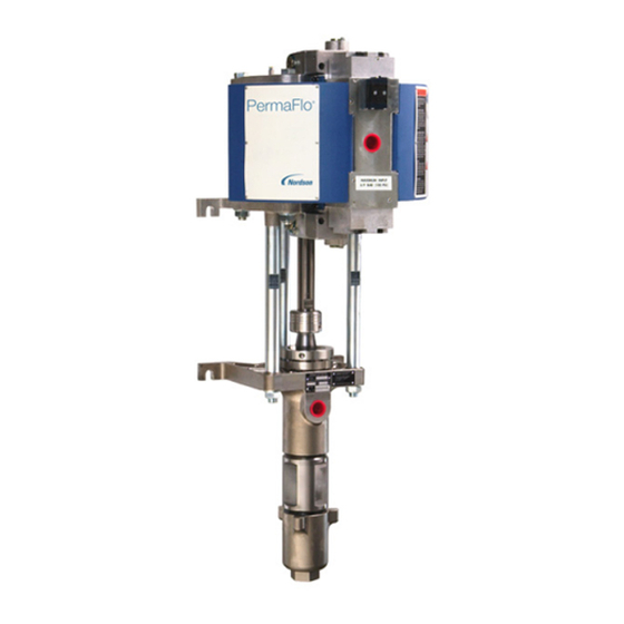
PermaFlor 830 Pump
Customer Product Manual
Part 1022914G03
Issued 8/07
For parts and technical support, call the
Finishing Customer Support Center at (800) 433-9319.
This document is subject to change without notice.
Check http://emanuals.nordson.com/finishing for the latest version.
NORDSON CORPORATION • AMHERST, OHIO • USA
Advertisement
Table of Contents

Subscribe to Our Youtube Channel
Related Manuals for Nordson PermaFlo Series


Summary of Contents for Nordson PermaFlo Series
- Page 1 Customer Product Manual Part 1022914G03 Issued 8/07 For parts and technical support, call the Finishing Customer Support Center at (800) 433-9319. This document is subject to change without notice. Check http://emanuals.nordson.com/finishing for the latest version. NORDSON CORPORATION • AMHERST, OHIO • USA...
- Page 2 Viton is a registered trademark of DuPont Dow Elastomers. L.L.C. Notice This is a Nordson Corporation publication which is protected by copyright. Original copyright date 2002. No part of this document may be photocopied, reproduced, or translated to another language without the prior written consent of Nordson Corporation.
- Page 3 ATEX Quality Notification − Baseefa (2001) Ltd (UK) Mike Hansinger Date: 28 November 2011 Manager Engineering Development Industrial Coating Systems Nordson Corporation NORDSON AUTHORIZED REPRESENTATIVE IN THE EU Contact: Operations Manager Industrial Coating Systems Nordson Deutschland GmbH Heinrich−Hertz−StraBe 42−44 D−40699 Erkrath...
-
Page 5: Table Of Contents
Air Filtration and Lubrication ......B 2-4 Part 1022914G03 E 2007 Nordson Corporation... - Page 6 ....C 1-15 New Style Air Valve (Pump Revisions D and Above) ..C 1-16 Part 1022914G03 E 2007 Nordson Corporation...
- Page 7 ......... D 2-12 Part 1022914G03 E 2007 Nordson Corporation...
- Page 8 New Style Air Motor (Pump Revisions D and Above) Old Style Air Valve (Pump Revisions A−C) New Style Air Valve (Pump Revisions D and Above) Old Style Hydraulic Section (Pump Revisions A−D) New Style Hydraulic Section (Pump Revisions E and Above) Part 1022914G03 E 2007 Nordson Corporation...
-
Page 9: Ce Declaration Of Conformity
DECLARATION of CONFORMITY Model : PermaFlo Series Air Operated Liquid Pump Applicable Directives : 94/9/EC (ATEX equipment for use in potentially explosive atmospheres) 98/37/EEC (Machinery) Standards Used for Compliance : IEC60417 EN1127-1 EN13463-5 EN12100 EN13463-1 Principles : This product has been manufactured according to good engineering practice. -
Page 10: Quick Reference
Part D: Air Motor and Hydraulic Section Parts Pump Revisions The ID plate on the front of the hydraulic section contains the Nordson part number and revision letter for each pump. Note the revision letter of your pump before using this manual, as it may contain reference to the revision letter or a range of revisions, if procedures or replacement parts were affected by a revision. -
Page 11: Operating Sound Levels
* 1 Cycle = 2 strokes (1 up and 1 down) High Pressure Hose WARNING: Use Nordson or equivalent nylon or PFTE fluid hoses, with electrical continuity between fittings. Fluid hose connected to the high pressure port must be capable of withstanding 206 bar (3000 psi). -
Page 12: Siphon Hose
V-rings waterborne and most solventborne materials. Ultra-High Molecular Weight Good for highly abrasive materials. Compatible with PolyEthylene (UHMWPE) waterborne and most solventborne materials. Slight swelling may occur when exposed to hydrocarbon solvents. Part 1022914G03 E 2007 Nordson Corporation... -
Page 13: Packing Kits
C: Noted kits used only on pump revisions D and above. D: Use 1027427 kit for pump revisions A−D, 1063360 kit for revisions E and above. E: Refer to Solvent Chamber Fluid in this section for the correct type for your application. Part 1022914G03 E 2007 Nordson Corporation... -
Page 14: Adhesives, Sealants, And Lubricants
244854 FLUID, type-Q concentrate (2.6 fluid ounce, makes one gallon) Solvent Chamber Fluid Guide Use this chart to select the proper solvent chamber fluid to use with your coating materials. For more information contact your Nordson representative. Solvent Type Material... -
Page 15: Options
D: Refer to Pump Ordering in this section and the identification plate on your pump for the packings shipped with your pump. Refer to Packing Materials and Applications in this section for information about packings. Part 1022914G03 E 2007 Nordson Corporation... -
Page 16: Safety
Regulations and Approvals Make sure all equipment is rated and approved for the environment in which it is used. Any approvals obtained for Nordson equipment will be voided if instructions for installation, operation, and service are not followed. Part 1022914G03... -
Page 17: Personal Safety
The National Spray Equipment Manufacturers Association has created a wallet card that you should carry when you are operating high-pressure spray equipment. These cards are supplied with your equipment. The following is the text of this card: Part 1022914G03 E 2007 Nordson Corporation... -
Page 18: Fire Safety
Refer to local codes or your material MSDS for guidance. Do not disconnect live electrical circuits when working with flammable materials. Shut off power at a disconnect switch first to prevent sparking. Part 1022914G03 E 2007 Nordson Corporation... -
Page 19: Halogenated Hydrocarbon Solvent Hazards
Clean, maintain, test, and repair equipment according to the instructions in your equipment documentation. Use only replacement parts that are designed for use with original equipment. Contact your Nordson representative for parts information and advice. Halogenated Hydrocarbon Solvent Hazards Do not use halogenated hydrocarbon solvents in a pressurized system that contains aluminum components. -
Page 20: Safety Labels
181147 MAXIMUM INPUT 6.9 BAR (100 PSI) - - - - - - MAXIMUM OPERATING PRESSURE 206 BAR (3000 PSI) Part 1022914G03 E 2007 Nordson Corporation... - Page 21 B 1-6 Safety 1300376A Figure B 1-1 Safety Labels Part 1022914G03 E 2007 Nordson Corporation...
-
Page 22: Description
Section B 2 Description Introduction The Nordson PermaFlo pumps are air-operated, demand-type, double-acting, reciprocating pumps designed to be mounted vertically on a wall, stand, or dolly. They can be used in dead-end or circulating systems. The PermaFlo model number indicates the air motor cylinder diameter and... -
Page 23: Pump Components
-in. pin punch, which can be purchased from an industrial supply company.) If the leaking continues the packings need to be replaced. Both upper and lower packings should be replaced at the same time. Part 1022914G03 E 2007 Nordson Corporation... - Page 24 15. Pressure ball check valve 4. Lower cylinder head 10. Valve assembly − air pilot valve 16. Plunger 5. Connecting rod 11. Hydraulic section 17. Solvent cup 6. Air piston 12. Upper packings 18. Coupling Part 1022914G03 E 2007 Nordson Corporation...
-
Page 25: Air Filtration And Lubrication
Refer to Section D1 Air Motor Parts for the optional Air Motor Accessory kit that includes a filter/regulator/gauge assembly. The air supply does not need to be lubricated. The moving parts of the air motor are chemically lubricated and do not require additional lubrication. Part 1022914G03 E 2007 Nordson Corporation... -
Page 26: Installation
WARNING: Install the pump according to all local codes and ordinances. Failure to do so is dangerous and could result in loss of agency approvals and voiding of Nordson warranties. WARNING: If any component of the high pressure fluid system has a maximum working pressure less than the pump’s, install a pressure relief... - Page 27 Remove the standard mufflers and replace them with the optional mufflers. Connect flexible hose to the muffler fittings. Slope the exhaust line downward away from the pump, to prevent moisture from collecting in the line and draining back into the air motor. Part 1022914G03 E 2007 Nordson Corporation...
- Page 28 Siphon Port if optional circulation valve valve kit is installed. Figure B 3-1 Mounting and Connections Male Connector Siphon Rod Siphon Hose Strainer Figure B 3-2 Installing Optional Siphon Accessory Kit (Dead-End System) Part 1022914G03 E 2007 Nordson Corporation...
-
Page 29: Installation Guidelines
High-pressure fluid connections must be tight and leak-free. Refer to Section B1 Safety for information on high pressure fluid hazards. Check all connections for leaks before beginning production. Part 1022914G03 E 2007 Nordson Corporation... - Page 30 9. Siphon hose 2. Drop leg 6. Air hose 10. High-pressure fluid hose 3. Drain valve 7. Coating supply 11. Fluid filter 4. Air shut off valve (self-relieving) 8. Siphon rod and strainer 12. Spray gun Part 1022914G03 E 2007 Nordson Corporation...
- Page 31 16. Drain hose and rod 5. Filter/Regulator/Gauge 11. Fluid filter 17. Waste container 6. Air hose 12. Spray gun Note: To install the optional circulation valve kit, refer to the instructions included with the kit. Part 1022914G03 E 2007 Nordson Corporation...
-
Page 32: Operation
(if used) are closed and the air regulator is set to zero pressure the system components (such as the heater and filter) have been installed according to the instructions in their manuals Part 1022914G03 E 2007 Nordson Corporation... -
Page 33: Solvent Cup Fill
Solvent Cup Fill Pump and System Flushing Frequency Flush the pump or system before you put it into service for the first time after you rebuild the hydraulic section when you change coating material Part 1022914G03 E 2007 Nordson Corporation... -
Page 34: Cleaning Solution For Flushing
NOTE: The fluid pressure at the spray gun(s) will vary, depending on many factors, including material viscosity and temperature, the number of filters and heaters, and fluid hose ID and length. Install a fluid pressure gauge at the spray gun(s) to determine the actual fluid pressure. Part 1022914G03 E 2007 Nordson Corporation... -
Page 35: Routine Shutdown
If the system will be shut down for more than a few days, flush it and leave it filled with cleaning solution. 4. Perform daily maintenance as described in Maintenance in this section. Part 1022914G03 E 2007 Nordson Corporation... - Page 36 1. Air shutoff valve 5. Siphon rod and strainer 9. Drain valve 2. Air filter/regulator/gauge 6. Fluid filter 10. Drain rod 3. Solvent cup 7. Fluid heater 11. Waster container 4. Coating supply 8. Circulation valve Part 1022914G03 E 2007 Nordson Corporation...
-
Page 37: Maintenance
Both upper and lower packings should be replaced at the same time. As Needed Flush the pump and system with a compatible cleaning solution. Change the solvent chamber fluid regularly. Clean the exterior of the pump. Part 1022914G03 E 2007 Nordson Corporation... -
Page 38: Troubleshooting
This section contains troubleshooting procedures. These procedures cover only the most common problems that you may encounter. If you cannot solve the problem with the information given here, contact your local Nordson representative for help. Problem Page Pump fails to start or stops while operating and fails to... -
Page 39: Common Problems
Check for air leaking around the heads leaking. cylinder heads. Replace the O-rings if they are leaking. Air valve seals worn Replace the seals. Air piston seal worn or damaged Replace the air piston. Continued... Part 1022914G03 E 2007 Nordson Corporation... - Page 40 Check the strainer screen. If the for coating material strainer screen is clogged with pigment, use a coarser mesh screen or a strainer without a screen. Contact your Nordson representative for advice. Continued... Part 1022914G03 E 2007 Nordson Corporation...
- Page 41 Upper packings worn Shut off pump, relieve hydraulic overflows often pressure, and tighten solvent cup turn. If leaking continues, replace the packings. Upper and lower packings should be replaced at the same time. Continued... Part 1022914G03 E 2007 Nordson Corporation...
-
Page 42: Preventing Air Valve Freezing
If you are operating the pump at high speed in a humid environment, lubricate the compressed air with a glycol-based antifreeze fluid. Do not use an antileak-type antifreeze fluid. Install an air dryer to remove moisture from the air supply. Part 1022914G03 E 2007 Nordson Corporation... - Page 43 B 5-6 Troubleshooting Part 1022914G03 E 2007 Nordson Corporation...
-
Page 44: Air Motor Repair
Large pliers or vice grips Large, flat, clean work bench MagnaLube-G or equivalent PTFE-impregnated grease (Nordson part 900349) Loctite 242 Removable thread adhesive or equivalent (Nordson part 900464) Replacement parts or kits (refer to Section D1 Air Motor Parts) Part 1022914G03... -
Page 45: Guidelines For O-Ring And Seal Replacement
Tighten to 10.2 ± 1 NDm (90 ± 10 in.-lb) when re-installing coupling. 1300386A Figure C 1-1 Coupling Removal and Replacement 21. Connecting rod 34. Coupling halves 32. Set screws A. Plunger 33. Coupling sleeve Part 1022914G03 E 2007 Nordson Corporation... -
Page 46: Coupling Replacement
Lift the air motor off the hydraulic section and move it to a clean, flat work surface. Customer-supplied fasteners 1300387B Figure C 1-2 Air Motor Removal 16. Lower cylinder head 36. Hex nuts 35. Air motor studs Part 1022914G03 E 2007 Nordson Corporation... -
Page 47: Air Pilot Valve Cartridge Replacement (Pump Revisions A−C) C
Air Pilot Valve (Actuator and Three-Way Valve Cartridge) Replacement − Pump Revisions A−C 4. Washer-head screws 6A. Actuator plunger 10. Valve cartridge 5. Flat washers 7. Plastic cap 10A. Valve ball 6. Actuator cartridge Part 1022914G03 E 2007 Nordson Corporation... -
Page 48: Air Pilot Valve Repair (Pump Revisions D And Above)
Air Pilot Valve (Actuator and Valve) Assembly − Pump Revisions D and Above 4A. Plug cap 4E. Cup seal 5B. Spring 4B. Plug with spring guide 4F. Plug 5C. Valve cartridge 4C. Spring 5A. Plug with O-ring 5D. Ball 4D. Plunger assembly Part 1022914G03 E 2007 Nordson Corporation... -
Page 49: Muffler And Air Valve Removal
Muffler and Air Valve Removal − Mufflers and Air Valve for Pump Revision D and Above Shown 12. Small O-rings 25. Air valve 28. Mufflers 13. Large O-rings 26. Large O-rings −20 x 1.375 in. socket-head screws 19. Short socket-head screws 27. Lock washers Part 1022914G03 E 2007 Nordson Corporation... -
Page 50: Air Motor Disassembly
NOTE: Unless the air motor studs (35) are damaged, there is no need to remove them. If you replace them, apply Loctite 242 Removable thread adhesive to the threads that screw into the lower cylinder head before installing the studs. Part 1022914G03 E 2007 Nordson Corporation... - Page 51 19. Short socket-head screws 24. Socket-head screw 14. Large O-rings 20. Hex nuts 27. Lock washers 15. Air cylinder 21. Connecting rod 35. Air motor studs 16. Lower cylinder head 22. Air piston 17. U-cup seal Part 1022914G03 E 2007 Nordson Corporation...
-
Page 52: Air Motor Re-Assembly
Tighten to 27 ± 4 NDm (20 ± 3 ft-lb) Left-hand threads: Turn clockwise to loosen, counterclockwise to tighten. Tighten 1300391B Figure C 1-7 Piston/Connecting Rod Assembly 21. Connecting rod 23. Flat washer 22. Air piston 24. Socket-head screw Part 1022914G03 E 2007 Nordson Corporation... -
Page 53: U-Cup Installation
Apply MagnaLube-G or equivalent PTFE grease to U-cup before installing. 1300392B Figure C 1-8 U-Cup Installation 16. Lower cylinder head 19. Socket-head screws 17. U-cup seal 21. Connecting rod 18. Backup plate 27. Lock washers Part 1022914G03 E 2007 Nordson Corporation... -
Page 54: Cylinder O-Ring Installation
O-ring on the upper cylinder head. 5. Install the four long hex-head screws (1) through the upper and lower cylinder heads and thread the hex nuts (20) loosely on the screws. Part 1022914G03 E 2007 Nordson Corporation... - Page 55 1300394B Figure C 1-10 Piston, Cylinder, and Cylinder Head Installation 1. Long hex-head screws 16. Lower cylinder head 21. Connecting rod 2. Upper cylinder head 20. Hex nuts 22. Air piston 15. Cylinder Part 1022914G03 E 2007 Nordson Corporation...
-
Page 56: Air Valve And Muffler Installation
Figure C 1-11 Muffler and Air Valve Installation − Mufflers and Air Valve for Pump Revision D and Above Shown 12. Small O-rings 25. Air valve 28. Mufflers 13. Large O-rings 26. Large O-rings −20 x 1.375 in. socket-head screws 19. Short socket-head screws 27. Lock washers Part 1022914G03 E 2007 Nordson Corporation... -
Page 57: Air Motor Rebuild Completion
4. If replacing the air pilot valve on a new style air valve assembly, install the fittings and connect the air tubing as shown in Figure C 1-14. Part 1022914G03 E 2007 Nordson Corporation... -
Page 58: Old Style Air Valve (Pump Revisions A−C)
Note: Item 6, shuttle (air pilot) valve, must be ordered separately. Items 3, 5, 8, and 10 are available in service kits. All other parts are only available as part of a new valve assembly. Part 1022914G03 E 2007 Nordson Corporation... -
Page 59: New Style Air Valve (Pump Revisions D And Above)
Note: Item 6, shuttle valve, must be ordered separately. Items 3, 5, 8, and 10 are available in service kits. Air tubing, tube fittings, mufflers, and pilot valve mounting parts are available separately. All other parts are only available as part of a new valve assembly. Part 1022914G03 E 2007 Nordson Corporation... -
Page 60: Hydraulic Section Repair
English hex wrench set Flat-bladed screwdrivers Large, flat, clean work surface Soft-jawed vise Parker O-Lube or equivalent O-ring lubricant (Nordson part 900223) Loctite 242 Removable thread adhesive or equivalent (Nordson part 900464) Parts and kits to replace damaged components. Refer to Section D2 Hydraulic Section Parts. -
Page 61: Guidelines For O-Ring And Seal Replacement
Tighten to 10.2 ± 1 NDm (90 ± 10 in.-lb) when re-installing coupling. Figure C 2-1 Coupling Removal and Replacement 8. Plunger C. Connecting rod A. Coupling sleeve D. Coupling halves B. Set screws Part 1022914G03 E 2007 Nordson Corporation... -
Page 62: Coupling Replacement
(7) to the pump mounting surface. 2. Have someone support the hydraulic section while you remove the three hex nuts (B) from the air motor studs (A). 3. Lower the hydraulic section off the studs. Part 1022914G03 E 2007 Nordson Corporation... -
Page 63: Disassembly
8. Remove the male and female adapters and V-rings (2, 3, and 4) from the ball seat. 9. Remove the ball cage (14), large ball (15), siphon ball seat (16), and white PTFE O-ring (17) from the siphon housing. Part 1022914G03 E 2007 Nordson Corporation... - Page 64 16. Siphon ball seat 5. Solvent cup adapter 11. O-rings (white PTFE) 17. O-ring (white PTFE) 6. Lip seal 12. Pressure housing 18. Siphon housing Note: Items 5 and 6 used on pump revisions A−D only. Part 1022914G03 E 2007 Nordson Corporation...
-
Page 65: Cleaning And Inspection
Pressure Lower Packing Assemblies NOTE: Apply Parker O-Lube or equivalent to all V-rings before assembling. Figure C 2-4 Packing Assemblies 2. Female adapter 4. Male adapter B. PTFE or UHMWPE V-rings A. Leather V-rings Part 1022914G03 E 2007 Nordson Corporation... - Page 66 6. Lip seal 7. Upper housing 3. Install the lower packing assembly onto the pressure ball seat (10) as shown. Packing Assembly Figure C 2-6 Installing the Lower Packing Assembly 10. Pressure ball seat Part 1022914G03 E 2007 Nordson Corporation...
-
Page 67: Solvent Cup Installation
Solvent Cup and Siphon Check Valve Assembly 1. Solvent cup 8. Plunger 5. Solvent cup adapter 9. Ball (small) (w/packings) 10. Pressure ball seat 7. Upper housing (w/packings) Note: Item 5 used on pump revisions A−D only. Part 1022914G03 E 2007 Nordson Corporation... - Page 68 4. Apply a thin film of O-ring lubricant to the ID of the pressure housing and the OD of the plunger. 5. Place the pressure housing in a vice, with the end that has the black Buna-N O-ring pointing down. Part 1022914G03 E 2007 Nordson Corporation...
-
Page 69: Upper Housing, Plunger, And Pressure Housing Assembly C
Figure C 2-9 Installing Plunger and Pressure Housing 1. Solvent cup 11. O-rings (white PTFE) A. Coupling sleeve 7. Upper housing 12. Pressure housing B. Connecting rod 8. Plunger 13. O-ring (black Buna-N) Part 1022914G03 E 2007 Nordson Corporation... -
Page 70: Siphon Housing Assembly And Installation
Apply Parker O-Lube or equivalent before installing. Figure C 2-10 Siphon Housing Assembly and Installation 12. Pressure housing 16. Siphon ball seat 14. Cage 17. O-ring (white PTFE) 15. Ball (large) 18. Siphon housing Part 1022914G03 E 2007 Nordson Corporation... -
Page 71: Return To Service
Install the circulation kit, if used, and connect the siphon and high-pressure fluid hoses. Connect the air supply hose to the air motor. Refer to Section B3, Installation, for connections and circulation valve installation. Flush the pump with a compatible cleaning solution and resume production. Part 1022914G03 E 2007 Nordson Corporation... -
Page 72: Air Motor Parts
Air Motor Parts Section D 1 Air Motor Parts Introduction To order parts, call the Nordson Finishing Customer Support Center at (800) 433−9319 or your local Nordson representative. Use these parts lists and illustrations to locate and describe parts correctly. Change Notice This notice details changes made to the air motor on revision D of the PermaFlo 830 pump assembly. - Page 73 - - - - - - COUPLING, shaft, retainer sleeve - - - - - - COUPLING, shaft 1021508 STUD, air motor, PermaFlo - - - - - - NUT, hex, flanged serrated, in., clear zinc Part 1022914G03 E 2007 Nordson Corporation...
- Page 74 B: Noted parts are included in the Coupler Kit, part 1024892. C: New style air valve (Figure D 1-4) used on pump revisions D and above. D: New style mufflers (Figure D 1-2) replaces old style curved mufflers. Part 1022914G03 E 2007 Nordson Corporation...
-
Page 75: Old Style Air Motor Parts (Pump Revisions A−C)
(6 and 10) are used, one set in upper cylinder head (2) and one set in lower cylinder head (16). Old Style Air Motor: Pump Revisions A−C 1300397B Figure D 1-1 Old Style Air Motor Parts (Pump Revisions A−C) Part 1022914G03 E 2007 Nordson Corporation... - Page 76 NOTE A: For parts breakdown, refer to New Style Air Valve Parts in this section. B: Muffler Kit, part 1021444, includes 1 muffler, 2 screws, 2 lockwashers, and two O-rings. C: Noted parts are included in the Coupler Kit, part 1024892. Part 1022914G03 E 2007 Nordson Corporation...
-
Page 77: New Style Air Motor Parts (Pump Revisions D And Above)
D 1-6 Air Motor Parts New Style Air Motor Pump Revisions D and Above 1300564A Figure D 1-2 New Style Air Motor Parts (Pump Revisions D and Above) Part 1022914G03 E 2007 Nordson Corporation... - Page 78 NOTE A: If you order a new air valve assembly, you will receive the new style valve shown in Figure D 1-4. B: Noted parts are included in the T-Seal Kit, part 1029057. C: Noted parts are included in the Spool and Seals Kit, part 1029058. Part 1022914G03 E 2007 Nordson Corporation...
- Page 79 D 1-8 Air Motor Parts OLD STYLE AIR VALVE 1300398A Figure D 1-3 Old Style Air Valve (Pump Revisions A−C) Part 1022914G03 E 2007 Nordson Corporation...
- Page 80 NOTE A: This version of the air valve assembly replaces the old style valve shown in Figure D 1-3. B: Noted parts are included in the T-Seal Kit, part 1029057. C: Noted parts are included in the Spool and Seals Kit, part 1029058. Part 1022914G03 E 2007 Nordson Corporation...
- Page 81 D 1-10 Air Motor Parts NEW STYLE AIR VALVE 1300563A Figure D 1-4 New Style Air Valve (Pump Revisions D and Above) Part 1022914G03 E 2007 Nordson Corporation...
-
Page 82: Service Kits
- - - - - - S SEAL, T NOTE A: The air valve T-seal kit may include an extra spring and two balls. These parts are not required to rebuild the valve and should be discarded. Part 1022914G03 E 2007 Nordson Corporation... -
Page 83: Air Valve Spool And Seals Kit
S ELBOW, male, 37, 1 −12 x -in. NPT, steel 802060 S HOSE, 5 foot 1029321 S REGULATOR assembly with filter 901236 S GAUGE, air, 0−100 psi, 0−7 kg/cm 1300399B Figure D 1-5 Air Motor Accessory Group Part 1022914G03 E 2007 Nordson Corporation... -
Page 84: Remote Exhaust Muffler Kit
−20 x 0.50 in., stainless steel - - - - - - S WASHER, lock, split, in. stainless steel 942230 S O-RING, hotpaint, 1.625 x 1.875 x 0.125 in. 1300433A Figure D 1-6 Remote Exhaust Muffler Kit Part 1022914G03 E 2007 Nordson Corporation... -
Page 85: Hydraulic Section Parts
A dash (—) is used when the part number applies to all parts in the illustration. The number in the Part column is the Nordson Corporation part number. A series of dashes in this column (- - - - - -) means the part cannot be ordered separately. - Page 86 B: Noted parts are included in the Hydraulic Seal Kit, part 1027527. C: Noted parts are included in the Pressure Ball Check Kit, part 1027525. D: Noted parts are included in the Siphon Ball Check Kit, part 1027526. Part 1022914G03 E 2007 Nordson Corporation...
- Page 87 D 2-3 Hydraulic Section Parts Pump Revisions A−D Only Figure D 2-1 Hydraulic Section Parts − Pump Revisions A−D Part 1022914G03 E 2007 Nordson Corporation...
- Page 88 B: Noted parts are included in the Hydraulic Seal Kit, part 1063360. C: Noted parts are included in the Pressure Ball Check Kit, part 1027525. D: Noted parts are included in the Siphon Ball Check Kit, part 1027526. Part 1022914G03 E 2007 Nordson Corporation...
- Page 89 D 2-5 Hydraulic Section Parts Type U Packings − Pump Revisions E and Above Figure D 2-2 Hydraulic Section with Type U Packings − Pump Revisions E and above Part 1022914G03 E 2007 Nordson Corporation...
- Page 90 B: Noted parts are included in the Hydraulic Seal Kit, part 1063360. C: Noted parts are included in the Pressure Ball Check Kit, part 1027525. D: Noted parts are included in the Siphon Ball Check Kit, part 1027526. Part 1022914G03 E 2007 Nordson Corporation...
- Page 91 D 2-7 Hydraulic Section Parts Type F Packings− Pump Revisions E and Above Figure D 2-3 Hydraulic Section with Type F Packings − Pump Revisions E and above Part 1022914G03 E 2007 Nordson Corporation...
-
Page 92: Packing Kits
- - - - - - S RING, V, leather, 1.422 x 2.028 x 0.083 - - - - - - S RING, V, 1.420 x 2.030, UHMWPE - - - - - - S ADAPTER, male, PermaFlo 830 Part 1022914G03 E 2007 Nordson Corporation... -
Page 93: Service Kits
S O-RING, PTFE, 2.234 x 2.512 x 0.139 in. - - - - - - S O-RING, −231, Buna-N, 70 duro - - - - - - S O-RING, PTFE, 2.050 x 2.256 x 0.103 in. Part 1022914G03 E 2007 Nordson Corporation... -
Page 94: Pressure Ball Check Kit
Use these adhesives, sealants, and lubricants when repairing the hydraulic section. Refer to Section C2 Hydraulic Section Repair for application instructions. Part Description Quantity 900464 ADHESIVE, threadlocking (Loctite Removable 242) 900223 LUBRICANT, O-ring, Parker (Parker O-Lube), 4 oz Part 1022914G03 E 2007 Nordson Corporation... -
Page 95: Siphon Accessory Group
S ROD, siphon, stainless steel, 1 in. pipe 249355 S STRAINER, siphon, stainless steel, 1 in. pipe 981279 S S SCREW, thumb, −20 x 1 in., stainless steel Figure D 2-5 Siphon Accessory Group Part 1022914G03 E 2007 Nordson Corporation... -
Page 96: Circulation Kit
S VALVE, ball, stainless steel 972103 S CONNECTOR, male, 37, −16 x stainless steel 823060 S HOSE, drain off, in. ID, 5 ft 750250 S ROD, drain off Figure D 2-6 Circulation Valve Kit Part 1022914G03 E 2007 Nordson Corporation... - Page 97 PermaFlor 815 and 830 Pumps Revisions A−C Air Motor Parts 1021378 CAP/PLUG ACTUATOR Nordson Customer Service: (800) 433-9319 (KIT A) 940180 SCREW O-RING 983058 WASHER 940154 O-RING 240976 1021313 132054 EYE BOLT GROUND CLAMP THREE-WAY VALVE RETAINER (KIT A) SCREW...
- Page 98 PermaFlor 815 and 830 Pumps Revision D and Above Air Motor Parts Nordson Customer Service: (800) 433-9319 982482 SCREW 983047 FLAT WASHER 240976 EYE BOLT 1063996 GROUND CLAMP ACTUATOR KIT (KIT C) 1063997 3-WAY VALVE KIT (KIT D) SCREW 941080...
- Page 99 PermaFlor 815 and 830 Pumps Revisions A−C Air Valve Parts Nordson Customer Service: (800) 433-9319 901166 VALVE SOCKET-HEAD SCREWS −20 x 1.375 in. STAINLESS STEEL SCREW END CAP O-RING VALVE BODY (KITS A, B) BRASS SLEEVE O-RING (KITS A, B)
- Page 100 PermaFlor 815 and 830 Pumps Revision D and Above Air Valve Parts Nordson Customer Service: (800) 433-9319 1080618 FITTING 972126 CONNECTOR 1062392 1058165 AIR PILOT 1080618 MUFFLERS VALVE FITTING 1065193 ELBOW 6-MM TUBING: 900586 -IN. TUBING: 900609 971291 971291 CONNECTOR...
- Page 101 PermaFlor 830 Hydraulic Section Parts − Pump Revisions A−D Nordson Customer Service: (800) 433-9319 1022003 O-RING SOLVENT CUP (KIT B) 1022046 1042327 FEMALE ADAPTER PLUNGER (KIT A) 1021892 PRESSURE HOUSING V-RINGS (KIT A) O-RING (KIT B) O-RING (KIT B) 1022596...
- Page 102 PermaFlor 830 Hydraulic Section Parts − Pump Revisions E and Above Nordson Customer Service: (800) 433-9319 O-RING 1022003 (KIT B) SOLVENT CUP 1022046 1042327 FEMALE ADAPTER PLUNGER (KIT A) 1021892 PRESSURE HOUSING V-RINGS (KIT A) O-RING (KIT B) O-RING (KIT B)
Need help?
Do you have a question about the PermaFlo Series and is the answer not in the manual?
Questions and answers