Table of Contents
Advertisement
Quick Links
CP Pump
Customer Product Manual
Part 104373−04
Issued 2/17
For parts and technical support, call the Industrial Coating Systems
Customer Support Center at (800) 433-9319
This document is subject to change without notice.
Check http://emanuals.nordson.com/finishing for the latest version.
NORDSON CORPORATION AMHERST, OHIO USA
Advertisement
Chapters
Table of Contents
Troubleshooting

Subscribe to Our Youtube Channel
Related Manuals for Nordson cp


Summary of Contents for Nordson cp
- Page 1 Part 104373−04 Issued 2/17 For parts and technical support, call the Industrial Coating Systems Customer Support Center at (800) 433-9319 This document is subject to change without notice. Check http://emanuals.nordson.com/finishing for the latest version. NORDSON CORPORATION AMHERST, OHIO USA...
- Page 2 Contact Us Notice This is a Nordson Corporation publication which is protected by copyright. Nordson Corporation welcomes requests for information, comments, and Original copyright date 1989. No part of this document may be inquiries about its products. General information about Nordson can be...
-
Page 3: Table Of Contents
Fluid Hose Connections ....... . . Part 104373−03 E 2015 Nordson Corporation... - Page 4 ........6-13 Air Tubing Diagram and Tube Chart ......6-14 Part 104373−03 E 2015 Nordson Corporation...
- Page 5 Siphon Ball Check Service Kit for Solventborne EPR Pumps ......7-26 Part 104373−03 E 2015 Nordson Corporation...
- Page 6 Table of Contents Part 104373−03 E 2015 Nordson Corporation...
- Page 7 Change Record Change Record Revision Date Change 10/15 Removed O-rings from siphon ball check valve service kit. 2/17 Updated certification. Part 104373−04 E 2017 Nordson Corporation...
- Page 8 Change Record Part 104373−04 E 2017 Nordson Corporation...
-
Page 9: Safety
Regulations and Approvals Make sure all equipment is rated and approved for the environment in which it is used. Any approvals obtained for Nordson equipment will be voided if instructions for installation, operation, and service are not followed. Part 104373−04... -
Page 10: Personal Safety
If you suffer a fluid injection injury, seek medical care immediately. If possible, provide a copy of the SDS for the injected fluid to the health care provider. Part 104373−04 E 2017 Nordson Corporation... -
Page 11: Fire Safety
Do not smoke, weld, grind, or use open flames where flammable materials are being used or stored. Do not heat materials to temperatures above those recommended by the manufacturer. Make sure heat monitoring and limiting devices are working properly. Part 104373−04 E 2017 Nordson Corporation... -
Page 12: Halogenated Hydrocarbon Solvent Hazards
Clean, maintain, test, and repair equipment according to the instructions in your equipment documentation. Use only replacement parts that are designed for use with original equipment. Contact your Nordson representative for parts information and advice. Halogenated Hydrocarbon Solvent Hazards Do not use halogenated hydrocarbon solvents in a pressurized system that contains aluminum components. -
Page 13: Safety Labels
Before servicing, cleaning, or removal of any part, set trigger lock on gun, and always shut off power source; then carefully release pressure in fluid portions of the system. NORDSON CORPORATION AMHERST, OH 44001 Figure 1-2 Main Safety Label Part 104373−04... - Page 14 Table 1-1 Safety Labels Item Part Description WARNING: Air motor section contains spring loaded pistons. Refer to − manual for disassembly instructions. General warning, caution, risk of danger. − Figure 1-3 ATEX Patent Label Part 104373−04 E 2017 Nordson Corporation...
-
Page 15: Description
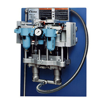
Description Section 2 Description Introduction The Nordson Constant Pressure (CP) pump is an air powered, positive displacement, demand-type, reciprocating dual piston pump. Table 2-1 CP Pump Versions Part Number and Type Description 130697 Used with solventborne coating materials. TFE/ General Finishing leather packings, Buna-N O-rings. -
Page 16: Fluid Pressures
Figure 2-1 Air Pressure-to-Fluid Pressure Ratios Fluid Hoses All hoses must be Nordson or equivalent PTFE hoses with electrical continuity between the fittings, capable of withstanding 207 bar (3000 psi) pressure. Do not use pipe in the high pressure circuit. -
Page 17: Air Pressure And Consumption
/min (80 psi) (5.72 cfm) (11.44 cfm) (17.16 cfm) Sound Levels Sound levels created by the CP pump are shown in decibels. Table 2-3 Sound Levels Air Pressure Sound Level (dB A) Sound Level (dB C) 7 bar (100 psi) 4.13 bar (60 psi) -
Page 18: Theory Of Operation
Working air is regulated and lubricated before flowing into the accumulator, air valve, and cylinders. When the pump is started, the position of the air valve spool determines which piston/plunger begins its downward (pressure) stroke first. Part 104373−03 E 2015 Nordson Corporation... - Page 19 Pump Control Regulator Accumulator Shutoff Filter Valve Pilot Air Regulator Lubricator Mufflers Air Valve Double Pilot Valve Air Cylinders Roller Valves Figure 2-3 Pump Pneumatic Schematic Part 104373−03 E 2015 Nordson Corporation...
- Page 20 1. Air valve 5. Solvent chamber 9. Siphon ball check valve 2. Muffler 6. Plunger 10. Siphon manifold 3. Piston 7. Packing gland 11. High-pressure ball check valve 4. Cylinder 8. Hydraulic housing 12. Outlet manifold Part 104373−03 E 2015 Nordson Corporation...
-
Page 21: Installation
2. Connect the pump to a true earth ground, using the ground strap and clamp provided. AIR MOTOR UPPER HEAD 120.6 mm (4.75 in.) 1450 mm (57 in.) AIR MOTOR LOWER HEAD 425.5 mm (16.75 in.) FLOOR Figure 3-1 Mounting Slot Pattern Part 104373−03 E 2015 Nordson Corporation... -
Page 22: Pneumatic Connections
The hose will serve as a vibration damper. 3. Install a shutoff valve (5) in the pressure feed line, ahead of the pump. Do not use a check valve or fluid regulator in the pressure supply line. Part 104373−03 E 2015 Nordson Corporation... -
Page 23: Optional Circulation Kit Installation
2. Connect the drain valves (3), drain hoses (4) and drain rods (5) to the circulation valves. Figure 3-3 Dual Circulation Valve Installation 1. Siphon manifold 4. Drain hoses 2. Circulation valves 5. Drain rods 3. Drain valves Part 104373−03 E 2015 Nordson Corporation... -
Page 24: Fluid Hose Connections
-in. ID high-pressure fluid hose (1) between the pump outlet manifold and the heater (2). Refer to Options in the Parts section for Nordson hoses. 2. Install a high-pressure fluid filter (3) between the heater and the spray device (4). -
Page 25: Operation
Fill the solvent chamber to within 13 mm ( in.) from the top. 2. Fill the air lubricator with the provided Nordson vitalizer oil. Do not adjust the lubricator at this time. Part 104373−03 E 2015 Nordson Corporation... -
Page 26: Solvent Flush
13. Reduce the air pressure to zero and close the air shutoff valve. 14. Drain the fluid filter. Clean the filter screen. Part 104373−03 E 2015 Nordson Corporation... -
Page 27: Daily Startup
If the system will be shut down for more than a few days, flush it and leave it filled with flush material. Part 104373−03 E 2015 Nordson Corporation... -
Page 28: Maintenance
4. While the pump is running, check the air lubricator oil level and delivery rate (1 drop every 15−20 strokes). Fill if necessary, using only Nordson vitalizer oil or an approved substitute. -
Page 29: Troubleshooting
Follow the safety instructions in this document and all other related documentation. These troubleshooting procedures cover only the most common problems that you may encounter. If you cannot solve the problem with the information given here, contact your local Nordson representative for help. Problem Page Pump fails to start... -
Page 30: Troubleshooting
If it does not move or is extremely tight, disassemble the valve and lubricate all parts. Replace any worn parts. If the spool slides back and forth easily, reinstall the end caps. Continued... Part 104373−03 E 2015 Nordson Corporation... -
Page 31: Pump Stops During Operation
The siphon hose may have a small hole or crack in it. Replace the hose. The two O-rings between the siphon manifold and the hydraulic housings may be leaking. Replace the O-rings. Continued... Part 104373−03 E 2015 Nordson Corporation... - Page 32 Faulty air valve If the pump continuously double strokes and either plunger is taking less than a 51-mm (2-in.) stroke and then reversing, the air valve is faulty. Rebuild or replace the air valve. Continued... Part 104373−03 E 2015 Nordson Corporation...
-
Page 33: Gradual Loss Of Fluid Pressure While Air Supply
Rebuild or replace the valve. Leaking siphon or high pressure Refer to Problem 4. ball check valves Continued... Part 104373−03 E 2015 Nordson Corporation... -
Page 34: Fluid Pressure Drops When The Spray Devices Are
Contact your Nordson representative for help in determining the proper circulation rate for your system. NOTE: Tails are streams Blocked fluid filter screen Clean the fluid filter screen. -
Page 35: Repair
Pump downtime can be reduced by replacing the packing glands and the air valve on-line. Refer to the Recommended Spare Parts lists on page 7-4 in the Parts section. Replace all O-rings affected by any disassembly procedure. Lubricate all O-rings with O-ring grease before installing. Part 104373−03 E 2015 Nordson Corporation... -
Page 36: Cover Removal
(1) to the pump. Remove the pump cover halves from the pump. 2. After repairing the pump, use the screws to reinstall the pump cover halves. Tighten the screws securely. Figure 6-1 Cover Removal 1. Cover half 2. Screws Part 104373−03 E 2015 Nordson Corporation... -
Page 37: Hydraulic Section Repair
Insert the packing gland tool (1) around the plunger (3). Place a hand under the solvent chamber to catch the packing gland. Press down on the packing gland tool to force out the packing gland. Part 104373−03 E 2015 Nordson Corporation... - Page 38 To return the pump to service, perform the following step. 9. Install the hydraulic housings over the plungers and packing glands. Use the screws, lockwashers, and washers to secure the housings to the solvent chamber. Tighten the screws to 20−27 NSm (15−20 lb-ft). Part 104373−03 E 2015 Nordson Corporation...
-
Page 39: Packing Gland Rebuild
5. Install the retaining ring with the sharp edge away from the spacer. Figure 6-4 Packing Gland Rebuild 1. Packing gland housing 3. Bearing 5. Spacer 2. O-rings 4. U-cup packing or seal 6. Retaining ring Part 104373−03 E 2015 Nordson Corporation... -
Page 40: Plunger Replacement
(1). Separate the siphon manifold from the hydraulic housings. 2. Thread the seat tool (8), furnished with the pump, into the seats (2). Pull on the tool until the seat breaks loose from the hydraulic housing. Remove the balls (7). Part 104373−03 E 2015 Nordson Corporation... -
Page 41: High-Pressure Ball Check Valve Rebuild
Rebuild both high-pressure ball check valves at the same time. 1. See Figure 6-2. Remove the hydraulic housings from the solvent chamber. 2. See Figure 6-6. Remove the siphon manifold from the hydraulic housings. Part 104373−03 E 2015 Nordson Corporation... - Page 42 13. Thread the cartridges into the hydraulic housings until they bottom out. 14. Assemble the outlet manifold and hydraulic housing assemblies. NOTE: Make sure the manifold outlet port faces toward the front of the pump. Part 104373−03 E 2015 Nordson Corporation...
-
Page 43: Air Valve Replacement
7. Install the tube fittings in the air valve. Connect the air tubing to the fittings. Reinstall the muffler cover Figure 6-8 Air Valve Replacement 1. Screws 4. Muffler cover 6. O-rings 2. Muffler box 5. Screws 7. Tube fittings 3. Exhaust tube Part 104373−03 E 2015 Nordson Corporation... -
Page 44: Air Valve Rebuild
Air Valve Rebuild 1. Red spacer (quantity 3) 5. Bumpers 9. O-rings 2. Silver spacer (quantity 2) 6. O-rings 10. Spool 3. O-ring 7. End caps 11. Fillet-head screws 4. Screws 8. End spacers Part 104373−03 E 2015 Nordson Corporation... -
Page 45: Air Motor Rebuild
2. Disconnect the ground strap from the upper pump head. 3. Drain the solvent chamber fluid. CAUTION: The CP pump weighs 48 kg (105 lb). Get help when lifting the pump off its mounting. 4. Remove the pump from the wall or stand. If desired, the hydraulic section, air preparation system, and air control components may be removed first. -
Page 46: Air Motor Assembly
Vitalizer oil. 6. Place the lower head/piston assembly on blocks. The blocks must hold the lower head high enough so that the end of the piston shaft does not touch the top of the workbench. Part 104373−03 E 2015 Nordson Corporation... -
Page 47: Air Preparation System
(5) then turning the bowl and pulling it off. NOTE: The air gauge and tubing fittings are not components of the air preparation system. They must be ordered separately. Part 104373−03 E 2015 Nordson Corporation... -
Page 48: Air Tubing Diagram And Tube Chart
Air Tubing Diagram and Tube Chart Tube Size (in. OD) Length mm (in.) 120 (4.75) 330 (13) 330 (13) 229 (9) 248 (9.75) 165 (6.5) 57 (2.25) 120 (4.75) Figure 6-12 Air Tubing Diagram and Tube Chart Part 104373−03 E 2015 Nordson Corporation... -
Page 49: Parts
A dash (—) is used when the part number applies to all parts in the illustration. The number in the Part column is the Nordson Corporation part number. A series of dashes in this column (- - - - - -) means the part cannot be ordered separately. -
Page 50: Parts Lists Table Of Contents
Service Kit Parts Lists 7-21 Air Valve Repair Kit 7-21 Air Motor Repair Kit 7-21 Packing Gland Service Kits 7-23 Hydraulic Seal Kits 7-24 High Pressure Ball Check Service Kits 7-25 Siphon Ball Check Service Kits Part 104373−03 E 2015 Nordson Corporation... -
Page 51: Quick Reference Lists
Parts Quick Reference Lists Pump Part Numbers Part Description Note 130697 Pump, stainless steel, general finishing, CP 249351 Pump, stainless steel, waterborne, CP 112246 Pump, stainless steel, solvent-based, CP 170494 Pump, stainless steel, solvent-based, CP, EPR 1004016 Pump, stainless steel, abrasive-resistant waterborne, CP... -
Page 52: Recommended Spare Parts
Circulation kit (general finishing, solventborne, waterborne, abrasive-resistant waterborne pumps) 179440 Circulation kit (solventborne EPR pumps) 179453 Circulation valve service kit (solventborne EPR pumps) 106244 Circulation valve carbide seat kit (abrasive-resistant waterborne pumps) 106251 Ball valve packing kit (all pumps) Part 104373−03 E 2015 Nordson Corporation... -
Page 53: Options
These hoses have 1 -12 JIC female swivel fittings. They are rated for 13.8 bar (200 psi) working pressure and have a in. inside diameter. Part Length mm (in.) 802018 457 (18) 802060 1524 (60) Part 104373−03 E 2015 Nordson Corporation... -
Page 54: Common Parts
Parts Common Parts See Figure 7-1. These parts are used on all versions of the CP pump. Item Part Description Quantity Note 106449 Valve assembly, air - - - - - - Air motor - - - - - -... - Page 55 Parts NOTE: Item 33 bracket shown and items 50−53 are used with SMC Air Preparation system only. Brackets used with Wilkerson system are obsolete. Figure 7-1 Common External Parts (1 of 2) Part 104373−03 E 2015 Nordson Corporation...
- Page 56 Parts Common Parts (contd) See Figure 7-1. These parts are used on all versions of the CP pump. Item Part Description Quantity Note 973434 Plug, square head, in. NPT, stainless steel 827060 Hose, siphon, in. ID, 5 ft, stainless steel fittings...
- Page 57 Parts NOTE: Item 33 bracket shown and items 50−53 are used with SMC Air Preparation system only. Brackets used with Wilkerson system are obsolete. Figure 7-1 Common External Parts (2 of 2) Part 104373−03 E 2015 Nordson Corporation...
-
Page 58: Air Valve Parts
S Screw, socket head, −18 x 1.5 in., Nylok NOTE A: Before installing, apply thread lock compound, part 900424 (VC-3). B: Included in air valve service kit part 106450. Refer to page 7-21 for kit parts list. Part 104373−03 E 2015 Nordson Corporation... - Page 59 7-11 Parts Figure 7-2 Air Valve Parts Part 104373−03 E 2015 Nordson Corporation...
-
Page 60: Air Motor Parts
NOTE A: Included in air motor service kit part 106451. Refer to page 7-21 for kit parts list. B: Only used on general finishing pump. C: Use 945064 O-ring, EPR, in. tube with EPR pumps. Part 104373−03 E 2015 Nordson Corporation... - Page 61 7-13 Parts Figure 7-3 Air Motor Parts Part 104373−03 E 2015 Nordson Corporation...
-
Page 62: Common Hydraulic Section Parts
B: Service kits available for solvent-borne, solvent EPR, waterborne, and abrasive resistant waterborne packing glands. Refer to Packing Gland Service Kits on page 7-21. C: Included in hydraulic seal (pages 7-23 and 7-23) and ball check (pages 7-23 and 7-25) service kits. Part 104373−03 E 2015 Nordson Corporation... - Page 63 7-15 Parts Figure 7-4 Common Hydraulic Section Parts Part 104373−03 E 2015 Nordson Corporation...
-
Page 64: Version-Specific Parts For Hydraulic Section
NPTF, w/O-ring 945099 S O-ring, EPR, in. tube NOTE A: Included in hydraulic seal and ball check service kits. Refer to Service Kits. B: Packing gland service kit available. Refer to page 7-21. Part 104373−03 E 2015 Nordson Corporation... -
Page 65: Abrasive Resistant Waterborne Pump (1004016)
Accessory groups are shipped with the pump. General Finishing and Solventborne Accessory Group Part Description Quantity 112244 Accessory group, CP pump, SB−GF 163031 S Strainer, siphon, 0.009 screen 941160 S S O-ring, hot paint, 0.75 x 0.938 x 0.094 in. 981205 S S Screw, thumb, −20 x 0.5 in. -
Page 66: Waterborne And Abrasive-Resistant Waterborne Accessory Group
−18 x 0.50 in., stainless steel Solventborne EPR Accessory Group Part Description Quantity 179443 Accessory group, CP pump, SB, EPR 179442 S Strainer, siphon, 0.006 screen, stainless steel, EPR 941164 S S O-ring, EPR, 0.75 x 0.938 x 0.093 in. 981279 S S Screw, thumb, −20 x 1 in., stainless steel... -
Page 67: Air Preparation Systems
Air Preparation Systems Wilkerson Air Preparation System See Figure 7-5. The air preparation system can be ordered through Nordson only as a unit. Individual modules and service parts can be ordered from the manufacturer or its distributors: Wilkerson Corporation Englewood, Colorado 80150... -
Page 68: Smc Air Preparation System
See Figure 7-5. The air preparation system can be ordered through Nordson only as a unit. Individual modules and service parts can be ordered from SMC or its distributors. NOTE: To retrofit a CP pump with this air preparation system, you must also order the mounting bracket listed here. Item... -
Page 69: Service Kits
Item Part Description Quantity Note — 106451 Service kit, air motor, CP pump 942610 S O-ring, Buna-N, square, 6.75 x 7.00 x 0.125 in. 952143 S Packing, U-cup, x 7.00 in. 954042 S Ring, backup, single, 6.50 x 7.00 in. -
Page 70: Solventborne And Waterborne Packing Gland Service Kit
S O-ring, hot paint, 2.5 x 2.75 x 0.125 in. 105066 S Bearing, plunger 952281 S U-cup, polyurethane, 1.62 x 2.25 in. 105065 S Spacer, packing 345318 S Ring, retaining, internal, 225, spiral, stainless steel Figure 7-7 Packing Gland Service Kits Part 104373−03 E 2015 Nordson Corporation... -
Page 71: Hydraulic Seal Kits
S O-ring, EPR, 2 x 2.125 x 0.063 in. 945064 S O-ring, EPR, tube 941163 S O-ring, EPR, 0.625 x 0.75 x 0.063 in. 940226 S O-ring, EPR, 1 x 1.125 x 0.063 in. Part 104373−03 E 2015 Nordson Corporation... -
Page 72: High-Pressure Ball Check Valve Service Kits
Item Part Description Quantity Note — 179450 Service kit, high-pressure check, CP, EPR — 942305 S O-ring, EPR, 2.50 x 2.75 x 0.125 in. 940335 S O-ring, EPR, 2.00 x 2.125 x 0.063 in. - - - - - -... -
Page 73: Abrasive-Resistant Waterborne Pumps
Part Description Quantity Note — 1004424 Service kit, high-pressure check, carbide, CP — 942300 S O-ring, hot paint, 2.50 x 2.75 x 0.125 in. 940330 S O-ring, hot paint, 2.00 x 2.125 x 0.063 in. - - - - - -... -
Page 74: Siphon Ball Check Service Kit For Solventborne Epr Pumps
S O-ring, hot paint, 1.375 x 1.625 x 0.125 in. 940335 S O-ring, EPR, 2.00 x 2.125 x 0.063 in. NOTE A: Pumps manufactured before June 1992 used nylon seats, which are interchangeable with the new stainless steel seats. Part 104373−03 E 2015 Nordson Corporation... - Page 76 CP Pump Refer to the CP Pump manual 104373 for complete service and parts information. Refer to the CP Pump manual 104373 for complete service and parts information. For parts and technical support call (800) 433-9319. For parts and technical support call (800) 433-9319.
- Page 77 Air Section Service Kits E - Air Motor Service Kit F - Air Valve Service Kit 106451 106450 900214 Vitalizer Oil (1 pint) ©2005 Nordson Corporation ©2005 Nordson Corporation 104373-QR...
- Page 78 1. Fill the lubricator bowl with Nordson Vitalizer oil. NOTE: Use only Nordson Vitalizer oil or an oil recommended by your Nordson representative. Disregard any oil recommendations in the OEM instruction sheet shipped with the air lubricator.
- Page 79 Issued 1/04 Original copyright date 1991. Nordson and the Nordson logo are registered trademarks of Nordson Corporation. E 2004 Nordson Corporation Part 108152E...
- Page 80 Medium K, S Aliphatic Petroleum Naphthas High T, Q K, S Mild K, S Chlorinated Solvents Medium High K, S Note 1: Type U packings may swell slightly when exposed to aromatic hydrocarbon solvents. Part 108044G E 2003 Nordson Corporation...
- Page 81 Solvent Chamber Fluid Parts List Part Description 248831 FLUID, type-S, pump chamber, one quart 900255 FLUID, type-K, pump chamber, one quart 140029 FLUID, type-T, pump chamber, one quart 244854 FLUID, type-Q concentrate (2.6 fluid ounce, makes one gallon) Part 108044G E 2003 Nordson Corporation...
- Page 82 4. Add the remaining distilled water to make one gallon, and mix for an additional 15 minutes. NOTE: The mixture may separate after prolonged shelf time. If it does, mix again before using. Part 108044G E 2003 Nordson Corporation...
- Page 83 Pump Packing and Solvent Chamber Fluid Guide Issued 10/03 Original copyright date 1990. Nordson and the Nordson logo are registered trademarks of Nordson Corporation. Part 108044G E 2003 Nordson Corporation...
Need help?
Do you have a question about the cp and is the answer not in the manual?
Questions and answers