Table of Contents
Advertisement
Quick Links
Nordson Corporation
OPERATOR'S CARD
P/N 1040272A
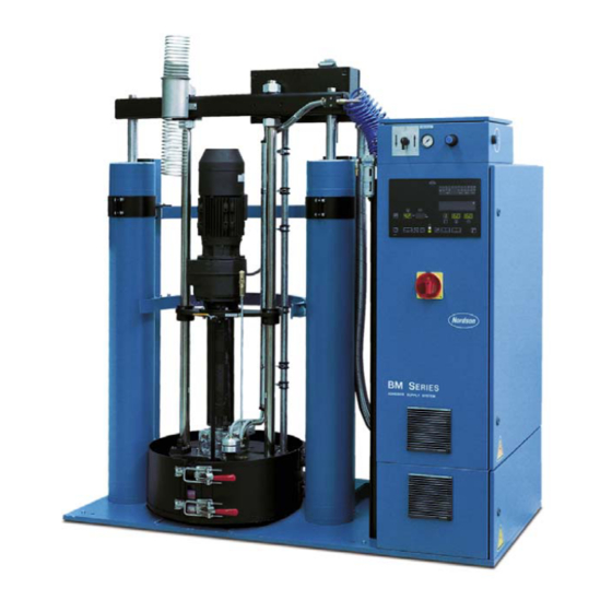
BM 200 Piston Pump Bulk Melter for 200 I Drums
S
Allow only qualified personnel to perform the
following tasks. Follow the safety instructions in
this document and all other related
documentation.
S
Risk of burns. Wear suitable protective clothing
when operating this equipment.
S
Obtain and read the Material Safety Data Sheets
for all materials used.
S
Immediately switch off this system in any
emergency situation.
RELATED DOCUMENTATION
References to other documents may be necessary to
supplement this operator's card. Review the
following documentation.
S
Bulk Melters BM 200
with Piston Pump for 200 I Drums
S
Control System CS 20
for Bulk Melters BM 20 / BM 200
S
Week Timer (Optional equipment)
CONSUMABLE ITEMS
Keep the following on hand when operating the
bulk melter.
ITEM
Centoplex HO
1
WARNING
PART
APPLICATION
285600
Melt platen sealing
ring lubricant
Advertisement
Table of Contents

Related Manuals for Nordson BM 200


Summary of Contents for Nordson BM 200
- Page 1 Nordson Corporation OPERATOR’S CARD P/N 1040272A BM 200 Piston Pump Bulk Melter for 200 I Drums WARNING Allow only qualified personnel to perform the following tasks. Follow the safety instructions in this document and all other related documentation. Risk of burns. Wear suitable protective clothing when operating this equipment.
-
Page 2: Operator Controls
Operator Controls Become familiar with the operator controls before Two-Hand Control operating the bulk melter. The two-hand control (1) on the pneumatic unit can only be operated by one person using both hands. It is used to lower the melt platen into the drum. When Pneumatic Unit the melt platen enters the drum, the system automatically switches to the regular lowering mode. - Page 3 Control System Motor Part See Figure 2. The control system consists of the motor part and temperature part. NOTE: The information in the shaded areas only apply to gear pumps. Switch on motor First press key 27 on the appropriate motor panel (motor is pre-selected, LED in key 27 is lit). Then press key 25 (motor is switched on, LED in key 25 and illuminated symbol 29 are lit).
- Page 4 Temperature Part See Figure 3. WARNING: The temperature prescribed by NOTE: Nordson Corporation assumes no guarantee and/or liability for damage caused by incorrect the material manufacturer is decisive. Do not temperature settings. exceed the maximum operating temperatures of the system and the heated system components.
-
Page 5: Initial Startup
Initial Startup NOTE: Special test material was used at the factory 7. Move melt platen to top position. to test this system. Residue from this material may be NOTE: The melt platen sealing rings must be on the melting plate and in the pump. To remove lubricated before initial startup and every time the residue, melt and feed several kilograms (pounds) of drum is replaced. - Page 6 Aerating Drum WARNING: Risk of burns. When the melt platen leaves the drum, hot material can come out and/or drip from the melt platen. Melt platen Wear suitable protective clothing. Compressed air See Figure 4. If the melt platen is inside of the drum, the drum must be aerated to support raising.
- Page 7 Deaerating System WARNING: Risk of burns. Hot material may flow out of the deaeration cock. Wear suitable protective clothing. The system must be deaerated upon initial startup and every time the drum is changed. The system is equipped with a deaeration cock for this purpose. NOTE: When the system is deaerated, the drum must be deaerated at the same time.
- Page 8 2. Adjust the switch rod (2) until it activates switch 4 when the upper sealing ring (3) is completely immersed in the drum. 3. Tighten the nut. Figure 8 Adjusting Switch Rod Issued 3/03 Original copyright date 2003. Nordson and the Nordson logo are registered trademarks of Nordson Corporation.
Need help?
Do you have a question about the BM 200 and is the answer not in the manual?
Questions and answers