Table of Contents
Advertisement
Quick Links
t
StediFlo
High Pressure
57:1 Pump
Customer Product Manual
Part 1601882-01
Issued 7/12
For parts and technical support, call the Industrial
Coating Systems Customer Support Center at (800) 433-9319
This document is subject to change without notice.
Check http://emanuals.nordson.com/finishing for the latest version.
NORDSON CORPORATION • AMHERST, OHIO • USA
Advertisement
Table of Contents
Troubleshooting

Subscribe to Our Youtube Channel
Related Manuals for Nordson StediFlo 57:1


Summary of Contents for Nordson StediFlo 57:1
- Page 1 Part 1601882-01 Issued 7/12 For parts and technical support, call the Industrial Coating Systems Customer Support Center at (800) 433-9319 This document is subject to change without notice. Check http://emanuals.nordson.com/finishing for the latest version. NORDSON CORPORATION • AMHERST, OHIO • USA...
-
Page 2: Table Of Contents
Declaration of Conformity Contact Us Notice This is a Nordson Corporation publication which is protected by copyright. Nordson Corporation welcomes requests for information, comments, and Original copyright date 2012. No part of this document may be inquiries about its products. General information about Nordson can be... -
Page 3: Safety
Regulations and Approvals Make sure all equipment is rated and approved for the environment in which it is used. Any approvals obtained for Nordson equipment will be voided if instructions for installation, operation, and service are not followed. Part 1601882-01... -
Page 4: Personal Safety
The National Spray Equipment Manufacturers Association has created a wallet card that you should carry when you are operating high-pressure spray equipment. These cards are supplied with your equipment. The following is the text of this card: Part 1601882-01 E 2012 Nordson Corporation... -
Page 5: Fire Safety
Refer to local codes or your material MSDS for guidance. Do not disconnect live electrical circuits when working with flammable materials. Shut off power at a disconnect switch first to prevent sparking. Part 1601882-01 E 2012 Nordson Corporation... -
Page 6: Halogenated Hydrocarbon Solvent Hazards
Clean, maintain, test, and repair equipment according to the instructions in your equipment documentation. Use only replacement parts that are designed for use with original equipment. Contact your Nordson representative for parts information and advice. Halogenated Hydrocarbon Solvent Hazards Do not use halogenated hydrocarbon solvents in a pressurized system that contains aluminum components. -
Page 7: Description
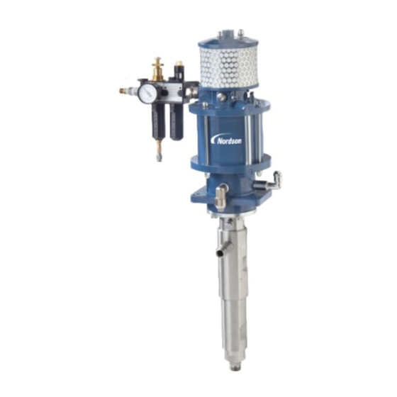
StediFlo 57:1 Pump Description The StediFlo 57:1 fluid pump is an air-operated, stainless steel pump suitable for solvent-based and waterborne coatings. It is a double-acting pump that delivers pressurized coatings on both the pressure and suction strokes. Coatings are siphoned into the pump only on the suction stroke. -
Page 8: Specifications
WARNING: Do not operate the pump at a higher operating pressure than the lowest maximum operating pressure of any component in the system. Failure to observe this warning could result in equipment damage or personal injury. Part 1601882-01 E 2012 Nordson Corporation... -
Page 9: Dimensions
StediFlo 57:1 Pump Dimensions ∅ 13 (4X) Solvent Chamber Filler Solvent Chamber Drain Figure 2 StediFlo 57:1 Pump Dimensions Part 1601882-01 E 2012 Nordson Corporation... -
Page 10: Installation
2. Drop leg 7. Coating supply 11. Fluid filter 3. Drain valve 8. Siphon rod and strainer 12. Spray gun 4. Air shut off valve (self-relieving) 9. Siphon hose 13. Drain valve 5. Filter/Regulator/Lubricator Part 1601882-01 E 2012 Nordson Corporation... -
Page 11: Circulating System Diagram
Mount the pump so that at least 10 cm (4 in.) of free space is left between the floor and the suction fitting. Refer to Options in the Parts section for an optional wall mounting bracket. Part 1601882-01 E 2012 Nordson Corporation... -
Page 12: Connections
See Figure 2. Remove the fill cap on the tee and fill the solvent chamber with approved solvent fluid until the fluid is visible approximately 1 cm (0.4 in.) below the fill opening. The chamber holds approximately 50 ml (1.7 fl. oz). Part 1601882-01 E 2012 Nordson Corporation... -
Page 13: Air Lubricator Oil
Fill the lubricator daily before starting production. The maximum oil level is indicated by a line on the reservoir. If high humidity causes icing of the air motor, fill the lubricator with pure anti-freeze solution, or heat the air. Part 1601882-01 E 2012 Nordson Corporation... -
Page 14: Flushing
Daily Operation 1. Check the solvent chamber level and fill if necessary. 2. Place the siphon strainer into a container of coating material, or supply coating material to the pump through a pressure feed system. Part 1601882-01 E 2012 Nordson Corporation... -
Page 15: Changing Colors Or Material
5. Ground the spray gun against the side of the waste container and spray into the container until all air is purged from the system and coating material flows smoothly from the gun, without spitting. Part 1601882-01 E 2012 Nordson Corporation... -
Page 16: Shutdown
Both upper and lower packings should be replaced at the same time. 6. Flush the pump and system at each material change. Part 1601882-01 E 2012 Nordson Corporation... -
Page 17: As Needed Maintenance
These troubleshooting procedures cover only the most common problems. If you cannot solve a problem with the information given here, contact your local Nordson representative for help. General Troubleshooting Refer to Air Motor Troubleshooting for problems specific to the air motor. - Page 18 Siphon hose too long, hose ID too Use the siphon hose shipped with small, or strainer screen too fine pump, or contact your Nordson for coating material representative. Check the strainer screen. If the strainer screen is clogged with pigment, use a coarser mesh screen or a strainer without a screen.
- Page 19 Refer to problem 1. outer edges Material too viscous Add solvent to the coating material to lower the viscosity. Damaged nozzle or fluid tip Replace the nozzle or fluid tip. Part 1601882-01 E 2012 Nordson Corporation...
-
Page 20: Air Motor Troubleshooting
Connecting rod spring (62 or 65) is Replace the spring(s). broken. Air motor fails to Insufficient air pressure or volume. Check compressor output, increase perform as expected. size of air line if necessary. Muffler is clogged. Replace the muffler(s). Part 1601882-01 E 2012 Nordson Corporation... -
Page 21: Hydraulic Section Repair
6. If the drain valve must be replaced, unscrew the valve housing (5.3) and remove it from the solvent chamber. 7. If the check valve needs repair, use a wrench to remove the check valve and seal (21, 22) from the middle housing (12). Part 1601882-01 E 2012 Nordson Corporation... -
Page 22: Air Motor / Hydraulic Section Separation
2. Use a hex wrench to remove the screw (20) from the bottom of the plunger. 3. Remove the valve seat (19), gasket (18), and ball (17). 4. Remove the retaining ring (16) with retaining ring pliers, then remove the ring (15) and retaining pin (23). Part 1601882-01 E 2012 Nordson Corporation... -
Page 23: Cleaning And Inspection
PTFE packing ring (30.3) e. Leather packing ring (30.2) PTFE packing ring (30.1) g. Counter ring (29) NOTE: The packing assembly should not extend above the top of the pressure cylinder. Always use new packings. Part 1601882-01 E 2012 Nordson Corporation... -
Page 24: Upper Packing Gland Assembly
12. Install the flange over the pressure cylinder and ends of the two side tie rods. 13. Install washers (25) and nuts (26) onto the two side tie rods. 14. Evenly tighten the two nuts to push the pressure cylinder and middle housing up against the solvent chamber. Part 1601882-01 E 2012 Nordson Corporation... -
Page 25: Air Motor Repair
3. Remove the pump from its mounting and move it to a clean workbench. 4. Disconnect the hydraulic section from the air motor. Refer to Hydraulic Section Repair for instructions on how to do this. Part 1601882-01 E 2012 Nordson Corporation... -
Page 26: Upper Control Housing Removal
3. Use pliers to remove the toggles (18) and toggle bearings (19). Remove the spring retainers (17) if necessary. 4. Remove the screws (42), washers (41), and cover plate (40) from the upper control plate (16). Part 1601882-01 E 2012 Nordson Corporation... -
Page 27: Lower Control Housing Removal
9. Use a 15-mm OD punch to tap out the lower sintered bearing (51). 10. Pull the two air inlet tubes and O-rings (70, 71, 73) out of the upper and lower cylinder plates (31, 74). Part 1601882-01 E 2012 Nordson Corporation... -
Page 28: Cylinder And Piston Removal
2. Use retaining ring pliers to install the retaining ring (72) in the lower cylinder plate. 3. Grease the O-ring groove in the lower cylinder plate and install the O-ring (69) in the groove. Part 1601882-01 E 2012 Nordson Corporation... -
Page 29: Piston Assembly
(55), into the end without flats. 3. Clamp the stop bolt in a bench vise and tighten the connecting rod with a wrench. 4. Grease the spring (65) with O-ring lubricant and install it into the motor axle (66). Part 1601882-01 E 2012 Nordson Corporation... -
Page 30: Cylinder Assembly
(29, 49), and 14 cap nuts and two ring nuts (not shown). Tighten the nuts hand-tight. The ring nuts must be installed opposite of each other, in front of or behind the air inlet tubes. Part 1601882-01 E 2012 Nordson Corporation... -
Page 31: Control Axle Assembly
9. Check the movement of the control axle (35). It should move freely without sticking. If there is any friction, loosen the cap nuts (28) and re-align the upper cylinder plate (31). Part 1601882-01 E 2012 Nordson Corporation... -
Page 32: Toggle Assembly Installation
8. Install the control cylinder into the control housing until the retaining ring rests on the housing. Use a bench vise if necessary to press the cylinder into the housing. Part 1601882-01 E 2012 Nordson Corporation... -
Page 33: Lower Control Housing Installation
(6) project through the top of the muffler housing. 3. Install the four washers (2) and cap nuts (1) on the extensions, then tighten the nuts in a criss-cross pattern. Part 1601882-01 E 2012 Nordson Corporation... -
Page 34: Parts Information
StediFlo 57:1 Pump Parts Information To order parts, call the Nordson Industrial Coating Systems Customer Support Center at (800) 433-9319 or contact your local Nordson representative. Pump Part Numbers Part Description Note 1601692 Pump, StediFlo 57:1 1601741 S Pump, hydraulic, StediFlo, 57:1... - Page 35 NOTE A: Included in 1601673 Seal Kit, 57:1, Hydraulic Section. This kit is also included in the repair kit. B: Included in 1601674 Repair Kit, 57:1, Hydraulic Section. This kit also includes the seal kit. C: Wear items. Keep on hand to avoid unnecessary downtime. NS: Not Shown Part 1601882-01 E 2012 Nordson Corporation...
-
Page 36: Air Motor Parts List
Valve, safety, 7 bar, air motor, StediFlo 1601390 Screw, control mounting, 57:1, air motor, StediFlo 1601384 Washer, top cover, air motor, StediFlo 1601363 Plate, cover, 57:1, air motor, StediFlo 1601378 Washer, cover plate, 57:1, air motor, StediFlo Continued... Part 1601882-01 E 2012 Nordson Corporation... - Page 37 Nut, compression, air motor, StediFlo 1601478 Valve, check, air motor, StediFlo 1601372 Tee, 57:1, air motor, StediFlo 1601394 Nut, compression, air motor, StediFlo 1601520 Tube, air, 57:1, air motor, StediFlo 1601519 Connector, air, 57:1, air motor, StediFlo Continued... Part 1601882-01 E 2012 Nordson Corporation...
-
Page 38: Options
Fluid, chamber, ISO, StediFlo, 3 liters 1602013 Fluid, chamber, ISO, StediFlo, 5 liters 1602014 Fluid, chamber, ISO, StediFlo, 10 liters 1602015 Fluid, chamber, ISO, StediFlo, 20 liters NOTE A: Use with isocyanide based coating materials. Part 1601882-01 E 2012 Nordson Corporation... - Page 39 F: Apply O-ring lubricant. M: Apply hydraulic pipe thread seal/adhesive. T: Apply solvent fluid. 30.1 ∅30 30.2 30.3 ∅20 30.4 30.5 30.6 22.1 22.2 22.3 22.4 R 1-1/2 G 3/4 Figure 6 StediFlo 57:1 Hydraulic Section Part 1601882-01 E 2012 Nordson Corporation...
- Page 40 StediFlo 57:1 Pump Part 1601882-01 E 2012 Nordson Corporation...
- Page 41 M: Apply hydraulic pipe thread adhesive/sealant. VIEW A Lower Housing (Item 74) Dimensions M25 x 1.5 (37) G 1/2 R 1/2 (50) (75) R 1/2 To Air Motor Figure 7 StediFlo 57:1 Air Motor Part 1601882-01 E 2012 Nordson Corporation...
- Page 42 StediFlo 57:1 Pump Part 1601882-01 E 2012 Nordson Corporation...
-
Page 43: Declaration Of Conformity
The product specified conforms to the directive and standards described above. Flammable Atmosphere Marking: Ex II 2G cT4 Date: 09 July 2012 Justin Hall Engineering Manager Industrial Coating Systems Nordson Authorized Representative in the EU Contact: Operations Manager Industrial Coating Systems Nordson Deutschland GmbH Heinrich−Hertz−StraBe 42−44 D−40699 Erkrath... - Page 44 Nordson Corporation D Amherst, Ohio D USA...
Need help?
Do you have a question about the StediFlo 57:1 and is the answer not in the manual?
Questions and answers