Table of Contents
Advertisement
Quick Links
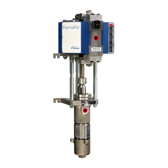
PermaFlor 815 Pump
Customer Product Manual
Part 1102698−07
Issued 03/19
For parts and technical support, call the
Industrial Coating Systems Customer Support Center at (800) 433-9319
This document is subject to change without notice.
Check http://emanuals.nordson.com/finishing for the latest version.
NORDSON CORPORATION • AMHERST, OHIO • USA
Advertisement
Table of Contents

Related Manuals for Nordson PermaFlo 815


Summary of Contents for Nordson PermaFlo 815
- Page 1 Part 1102698−07 Issued 03/19 For parts and technical support, call the Industrial Coating Systems Customer Support Center at (800) 433-9319 This document is subject to change without notice. Check http://emanuals.nordson.com/finishing for the latest version. NORDSON CORPORATION • AMHERST, OHIO • USA...
- Page 2 All other trademarks are the property of their respective owners. Notice This is a Nordson Corporation publication which is protected by copyright. Original copyright date 2008. No part of this document may be photocopied, reproduced, or translated to another language without the prior written consent of Nordson Corporation.
- Page 3 7/12 Added Type F self-adjusting packings pump 1602026. 10/16 Updated gauge port. 11/18 Update self-adjust hydraulic section repair. 3/19 Added ATEX label. 3/19 Updated part number 900223 to 1612251. 3/19 Removed O-ring from 1021635. Part 1102698−07 E 2019 Nordson Corporation...
- Page 4 Change Record Part 1102698−07 E 2019 Nordson Corporation...
-
Page 5: Table Of Contents
........B 3-4 Part 1102698−07 E 2019 Nordson Corporation... - Page 6 ........C 1-13 Part 1102698−07 E 2019 Nordson Corporation...
- Page 7 Remote Exhaust Muffler Kit ......D 1-8 Part 1102698−07 E 2019 Nordson Corporation...
- Page 8 ........D 2-13 Part 1102698−07 E 2019 Nordson Corporation...
- Page 9 ® PermaFlo 815 Pump Service Kits Refer to PermaFlo 815 Pump Manual 1085470 for complete service and parts information. For parts and technical support call (800) 433-9319 Actuator Kit 1063996 3-Way Valve Kit 1063997 T-Seal Kit 1029057 Spool and T-Seal Kit...
-
Page 10: Quick Reference
Use this section to quickly find specifications and parts information for the PermaFlo 815 pump. Pump Revisions The ID plate on the front of the hydraulic section contains the Nordson part number and revision letter for each pump. This manual covers the following pumps:... -
Page 11: Air Requirements
* 1 Cycle = 2 strokes (1 up and 1 down) High Pressure Hose WARNING: Use Nordson or equivalent nylon or PTFE fluid hoses, with electrical continuity between fittings. Fluid hose connected to the high pressure port must be capable of withstanding 103 bar (1500 psi). -
Page 12: Pump Ordering
A 1-3 Quick Reference Pump Ordering Use the part numbers below to order a complete new PermaFlo 815 pump. Pumps include the packing type indicated. Refer to packing kits below for other packing types available. Part Description 1024648 PUMP, PermaFlo 815, Type U packings... -
Page 13: Air Motor And Air Valve Kits
Description Note 1029666 KIT, ball, pressure check, PermaFlo 815 1086479 KIT, ball, pressure check, PermaFlo 815, self adjusting 1029667 KIT, ball, siphon check, PermaFlo 815 1063201 KIT, hydraulic, seal, PermaFlo 815 NOTE A: Use with standard packings only (Type U, F, L). Included in 1024648 or 1065204 pumps. -
Page 14: Adhesives, Sealants, And Lubricants
244854 FLUID, type-Q concentrate (2.6 fluid ounce, makes one gallon) Solvent Chamber Fluid Guide Use this chart to select the proper solvent chamber fluid to use with your coating materials. For more information contact your Nordson representative. Solvent Type Material... -
Page 15: Options
1037841 KIT, packing, Type L, PermaFlo 815 1089172 KIT, packing, Type F, PermaFlo 815, self adjusting 973391 BUSHING, reduction, 3/4 x 3/8 in. NPT, steel, zinc NOTE A: An air lubricator is not required. All elastomers in the air motor are self-lubricating. -
Page 16: Safety
Regulations and Approvals Make sure all equipment is rated and approved for the environment in which it is used. Any approvals obtained for Nordson equipment will be voided if instructions for installation, operation, and service are not followed. Part 1102698−07... -
Page 17: Personal Safety
The National Spray Equipment Manufacturers Association has created a wallet card that you should carry when you are operating high-pressure spray equipment. These cards are supplied with your equipment. The following is the text of this card: Part 1102698−07 E 2019 Nordson Corporation... -
Page 18: Fire Safety
Refer to local codes or your material SDS for guidance. Do not disconnect live electrical circuits when working with flammable materials. Shut off power at a disconnect switch first to prevent sparking. Part 1102698−07 E 2019 Nordson Corporation... -
Page 19: Halogenated Hydrocarbon Solvent Hazards
Clean, maintain, test, and repair equipment according to the instructions in your equipment documentation. Use only replacement parts that are designed for use with original equipment. Contact your Nordson representative for parts information and advice. Halogenated Hydrocarbon Solvent Hazards Do not use halogenated hydrocarbon solvents in a pressurized system that contains aluminum components. -
Page 20: Safety Labels
Before servicing, cleaning, or removal of any part, set trigger lock on gun, and always shut off power source; then carefully release pressure in fluid portions of the system. 181147 MAXIMUM INPUT 6.9 BAR (100 PSI) − MAXIMUM OPERATING PRESSURE 103 BAR (1500 PSI) Part 1102698−07 E 2019 Nordson Corporation... - Page 21 B 1-6 Safety Figure B 1-1 Safety Labels 1609843 Figure B 1-2 ATEX Label Part 1102698−07 E 2019 Nordson Corporation...
-
Page 22: Description
Section B 2 Description Introduction The Nordson PermaFlo pumps are air-operated, demand-type, double-acting, reciprocating pumps designed to be mounted vertically on a wall, stand, or dolly. They can be used in dead-end or circulating systems. The PermaFlo model number indicates the air motor cylinder diameter and... -
Page 23: Pump Components
-in. pin punch, which can be purchased from an industrial supply company.) If the leaking continues the packings need to be replaced. Both upper and lower packings should be replaced at the same time. Part 1102698−07 E 2019 Nordson Corporation... - Page 24 15. Pressure ball check valve 4. Lower cylinder head 10. Valve assembly − air pilot valve 16. Plunger 5. Connecting rod 11. Hydraulic section 17. Solvent cup 6. Air piston 12. Upper packings 18. Coupling Part 1102698−07 E 2019 Nordson Corporation...
-
Page 25: Air Filtration And Lubrication
Refer to Section D1 Air Motor Parts for the optional Air Motor Accessory kit that includes a filter/regulator/gauge assembly. The air supply does not need to be lubricated. The moving parts of the air motor are chemically lubricated and do not require additional lubrication. Part 1102698−07 E 2019 Nordson Corporation... -
Page 26: Installation
WARNING: Install the pump according to all local codes and ordinances. Failure to do so is dangerous and could result in loss of agency approvals and voiding of Nordson warranties. WARNING: If any component of the high pressure fluid system has a maximum working pressure less than the pump’s, install a pressure relief... - Page 27 Remove the standard mufflers and replace them with the optional mufflers. Connect flexible hose to the muffler fittings. Slope the exhaust line downward away from the pump, to prevent moisture from collecting in the line and draining back into the air motor. Part 1102698−07 E 2019 Nordson Corporation...
- Page 28 Siphon Port if optional circulation valve valve kit is installed. Figure B 3-1 Mounting and Connections Male Connector Siphon Rod Siphon Hose Strainer Figure B 3-2 Installing Optional Siphon Accessory Kit (Dead-End System) Part 1102698−07 E 2019 Nordson Corporation...
-
Page 29: Installation Guidelines
High-pressure fluid connections must be tight and leak-free. Refer to Section B1 Safety for information on high pressure fluid hazards. Check all connections for leaks before beginning production. Part 1102698−07 E 2019 Nordson Corporation... - Page 30 9. Siphon hose 2. Drop leg 6. Air hose 10. High-pressure fluid hose 3. Drain valve 7. Coating supply 11. Fluid filter 4. Air shut off valve (self-relieving) 8. Siphon rod and strainer 12. Spray gun Part 1102698−07 E 2019 Nordson Corporation...
- Page 31 16. Drain hose and rod 5. Filter/Regulator/Gauge 11. Fluid filter 17. Waste container 6. Air hose 12. Spray gun Note: To install the optional circulation valve kit, refer to the instructions included with the kit. Part 1102698−07 E 2019 Nordson Corporation...
-
Page 32: Operation
(if used) are closed and the air regulator is set to zero pressure the system components (such as the heater and filter) have been installed according to the instructions in their manuals Part 1102698−07 E 2019 Nordson Corporation... -
Page 33: Solvent Cup Fill
Solvent Cup Fill Pump and System Flushing Frequency Flush the pump or system before you put it into service for the first time after you rebuild the hydraulic section when you change coating material Part 1102698−07 E 2019 Nordson Corporation... -
Page 34: Cleaning Solution For Flushing
For example, you want an output pressure of 1200 psi. Calculate the required air pressure as follows: PermaFlo 815: 1200 psi 15 = 80 psi air pressure required. PermaFlo 830: 1200 psi 30 = 40 psi air pressure required. -
Page 35: Routine Shutdown
If the system will be shut down for more than a few days, flush it and leave it filled with cleaning solution. 4. Perform daily maintenance as described in Maintenance in this section. Part 1102698−07 E 2019 Nordson Corporation... - Page 36 1. Air shutoff valve 5. Siphon rod and strainer 9. Drain valve 2. Air filter/regulator/gauge 6. Fluid filter 10. Drain rod 3. Solvent cup 7. Fluid heater 11. Waster container 4. Coating supply 8. Circulation valve Part 1102698−07 E 2019 Nordson Corporation...
-
Page 37: Maintenance
As Needed Flush the pump and system with a compatible cleaning solution. Change the solvent chamber fluid regularly. Clean the exterior of the pump. Part 1102698−07 E 2019 Nordson Corporation... -
Page 38: Troubleshooting
These procedures cover only the most common problems that you may encounter. If you cannot solve the problem with the information given here, contact your local Nordson representative for help. Problem Page Pump fails to start or stops while operating and fails to... - Page 39 Replace the valve if damaged. Clean and inspect both air pilot actuators. Replace them if damaged. Air supply contaminated Check air filtration system. Air valve damaged Rebuild air valve. Continued... Part 1102698−07 E 2019 Nordson Corporation...
- Page 40 Lower heater thermostat setting. Worn or clogged ball check valve Flush the pump and system with a compatible cleaning solution. If the problem continues, rebuild the ball check valves. Worn packings Replace the packings. Continued... Part 1102698−07 E 2019 Nordson Corporation...
- Page 41 Check the strainer screen. If the for coating material strainer screen is clogged with pigment, use a coarser mesh screen or a strainer without a screen. Contact your Nordson representative for advice. Continued... Part 1102698−07 E 2019 Nordson Corporation...
- Page 42 Upper packings worn Shut off pump, relieve hydraulic overflows often pressure, and tighten solvent cup turn. If leaking continues, replace the packings. Upper and lower packings should be replaced at the same time. Continued... Part 1102698−07 E 2019 Nordson Corporation...
-
Page 43: Preventing Air Valve Freezing
If you are operating the pump at high speed in a humid environment, lubricate the compressed air with a glycol-based antifreeze fluid. Do not use an antileak-type antifreeze fluid. Install an air dryer to remove moisture from the air supply. Part 1102698−07 E 2019 Nordson Corporation... -
Page 44: Air Motor Repair
Large pliers or vice grips Large, flat, clean work bench MagnaLube-G or equivalent PTFE-impregnated grease (Nordson part 900349) Loctite 242 Removable thread adhesive or equivalent (Nordson part 900464) Replacement parts or kits (refer to Section D1 Air Motor Parts) Part 1102698−07... -
Page 45: Guidelines For O-Ring And Seal Replacement
Tighten to 10.2 ± 1 NDm (90 ± 10 in.-lb) when re-installing coupling. Figure C 1-1 Coupling Removal and Replacement 21. Connecting rod 34. Coupling halves 32. Set screws A. Plunger 33. Coupling sleeve Part 1102698−07 E 2019 Nordson Corporation... -
Page 46: Coupling Replacement
Lift the air motor off the hydraulic section and move it to a clean, flat work surface. Customer-supplied fasteners Figure C 1-2 Air Motor Removal 16. Lower cylinder head 36. Hex nuts 35. Air motor studs Part 1102698−07 E 2019 Nordson Corporation... -
Page 47: Air Pilot Valve Repair
All components of the air pilot valves, except the cup seal (4E), can be removed and replaced without disassembling the air motor. NOTE: If you have the cartridge-type air pilot valves, refer to manual 1032967, available on http://emanuals.nordson.com/finishing. Apply MagnaLube-G or equivalent PTFE grease to external O-rings before installing. -
Page 48: Muffler And Air Valve Removal
Figure C 1-4 Muffler and Air Valve Removal 12. Small O-rings 25. Air valve 28. Mufflers 13. Large O-rings 26. Large O-rings −20 x 1.375 in. socket-head screws 19. Short socket-head screws 27. Lock washers Part 1102698−07 E 2019 Nordson Corporation... -
Page 49: Air Motor Disassembly
NOTE: Unless the air motor studs (35) are damaged, there is no need to remove them. If you replace them, apply Loctite 242 Removable thread adhesive to the threads that screw into the lower cylinder head before installing the studs. Part 1102698−07 E 2019 Nordson Corporation... - Page 50 19. Short socket-head screws 24. Socket-head screw 14. Large O-rings 20. Hex nuts 27. Lock washers 15. Air cylinder 21. Connecting rod 35. Air motor studs 16. Lower cylinder head 22. Air piston 17. U-cup seal Part 1102698−07 E 2019 Nordson Corporation...
-
Page 51: Air Motor Re-Assembly
Tighten to 27 ± 4 N (20 ± 3 ft-lb) Left-hand threads: Turn clockwise to loosen, counterclockwise to tighten. Tighten Figure C 1-6 Piston/Connecting Rod Assembly 21. Connecting rod 23. Flat washer 22. Air piston 24. Socket-head screw Part 1102698−07 E 2019 Nordson Corporation... -
Page 52: U-Cup Installation
Apply MagnaLube-G or equivalent PTFE grease to U-cup before installing. Figure C 1-7 U-Cup Installation 16. Lower cylinder head 19. Socket-head screws 17. U-cup seal 21. Connecting rod 18. Backup plate 27. Lock washers Part 1102698−07 E 2019 Nordson Corporation... -
Page 53: Cylinder O-Ring Installation
O-ring on the upper cylinder head. 5. Install the four long hex-head screws (1) through the upper and lower cylinder heads and thread the hex nuts (20) loosely on the screws. Part 1102698−07 E 2019 Nordson Corporation... - Page 54 Figure C 1-9 Piston, Cylinder, and Cylinder Head Installation 1. Long hex-head screws 16. Lower cylinder head 21. Connecting rod 2. Upper cylinder head 20. Hex nuts 22. Air piston 15. Cylinder Part 1102698−07 E 2019 Nordson Corporation...
-
Page 55: Air Valve And Muffler Installation
Figure C 1-10 Muffler and Air Valve Installation 12. Small O-rings 25. Air valve 28. Mufflers 13. Large O-rings 26. Large O-rings −20 x 1.375 in. socket-head screws 19. Short socket-head screws 27. Lock washers Part 1102698−07 E 2019 Nordson Corporation... -
Page 56: Air Motor Rebuild Completion
4. If replacing the air pilot valve on a new style air valve assembly, install the fittings and connect the air tubing as shown in Figure C 1-12. Part 1102698−07 E 2019 Nordson Corporation... - Page 57 Note: Item 6, shuttle valve, must be ordered separately. Items 3, 5, 8, and 10 are available in service kits. Air tubing, tube fittings, mufflers, and pilot valve mounting parts are available separately. All other parts are only available as part of a new valve assembly. Part 1102698−07 E 2019 Nordson Corporation...
-
Page 58: Hydraulic Section Repair
English hex wrench set Flat-bladed screwdrivers Large, flat, clean work surface Soft-jawed vise Parker O-Lube or equivalent O-ring lubricant (Nordson part 1612251) Loctite 242 Removable thread adhesive or equivalent (Nordson part 900464) Parts and kits to replace damaged components. Refer to Section D2 Hydraulic Section Parts. -
Page 59: Guidelines For O-Ring And Seal Replacement
Tighten to 10.2 ± 1 N (90 ± 10 in.-lb) when re-installing coupling. Figure C 2-1 Coupling Removal and Replacement 4. Plunger C. Connecting rod A. Coupling sleeve D. Coupling halves B. Set screws Part 1102698−07 E 2019 Nordson Corporation... -
Page 60: Coupling Replacement
(16) from the air motor studs (15). 3. Lower the hydraulic section off the studs (15). Customer-supplied fasteners Figure C 2-2 Hydraulic Section Removal 3. Upper housing 16. Hex nuts 15. Air motor studs Part 1102698−07 E 2019 Nordson Corporation... -
Page 61: Disassembly
12. Remove the upper packing assembly (2) from the upper housing. Self-adjusting packings include wave springs and backup washers, Type D packings also include shims. 13. Remove the white PTFE O-rings (7) and the black Buna-N O-ring (9) from the pressure housing (8). Part 1102698−07 E 2019 Nordson Corporation... - Page 62 2. Packings 7. O-rings (white PTFE) 12. Siphon ball seat 3. Upper housing 8. Pressure housing 13. O-ring (white PTFE) 4. Plunger 9. O-ring (black Buna-N) 14. Siphon housing 5. Ball (small) 10. Cage Part 1102698−07 E 2019 Nordson Corporation...
-
Page 63: Cleaning And Inspection
Upper Female Adapter UHMWPE V-rings (6) Male Adapter Pressure Male Adapter UHMWPE V-rings (4) Female Adapter Lower Figure C 2-4 Type U Standard Packing Assemblies Part 1102698−07 E 2019 Nordson Corporation... -
Page 64: Type L Standard Packing Assemblies
PTFE V-ring Leather V-ring PTFE V-ring Leather V-ring PTFE V-ring Male Adapter Pressure Male Adapter PTFE V-ring Leather V-ring PTFE V-ring Leather V-ring Female Adapter Lower Figure C 2-6 Type F Standard Packing Assemblies Part 1102698−07 E 2019 Nordson Corporation... -
Page 65: Type F Self-Adjusting Packing Assemblies
Shims Upper Female Adapter V-rings (3) Male Adapter Washer Wave Springs (2) Pressure Wave Springs (2) Washer Male Adapter V-rings (3) Female Adapter Shims Lower Figure C 2-8 Type D Self-Adjusting Packing Assemblies Part 1102698−07 E 2019 Nordson Corporation... -
Page 66: Changing Packing Gland Type
Installing the Packing Assemblies 2A. Female adapter 2D. Shims (Type D self-adjusting only) 3. Upper housing 2B. V-rings 2E. Washer (self-adjusting only) 6. Pressure ball seat 2C. Male adapter 2F. Wave springs (self-adjusting only) Part 1102698−07 E 2019 Nordson Corporation... -
Page 67: Hydraulic Section Assembly And Installation
11. Center the plunger (4) and pressure housing (8) with the alignment tool, and then remove the tool. NOTE: The Nordson alignment tool is recommended to make assembly easier, but the tool is not essential. Part 1102698−07... - Page 68 C 2-11 Hydraulic Section Repair Figure C 2-10 Pressure Housing and Plunger Assembly 4. Plunger 7. O-rings (white PTFE) 5. Ball (small) 8. Pressure housing 6. Pressure ball seat (with packings) 9. O-ring (black Buna-N) Part 1102698−07 E 2019 Nordson Corporation...
- Page 69 (3). 5. Screw the solvent cup (1) into the upper housing and tighten hand tight. Figure C 2-11 Upper Housing Assembly 1. Solvent cup 4. Plunger 3. Upper housing 8. Pressure housing Part 1102698−07 E 2019 Nordson Corporation...
- Page 70 (8) and tighten hand tight. Remove the pressure housing from the soft-jawed vise. Figure C 2-12 Siphon Housing Assembly 8. Pressure housing 12. Siphon ball seat 10. Cage 13. O-ring (white PTFE) 11. Ball (large) 14. Siphon housing Part 1102698−07 E 2019 Nordson Corporation...
- Page 71 Tighten to 136 ± 14 NSm (100 ± 10 ft-lb). Customer-supplied fasteners Figure C 2-13 Hydraulic Section Installation 1. Solvent cup 15. Air motor studs 17. Connecting rod 3. Upper housing 16. Hex nuts 18. Coupling sleeve 4. Plunger Part 1102698−07 E 2019 Nordson Corporation...
-
Page 72: Return To Service
Install the circulation kit, if used, and connect the siphon and high-pressure fluid hoses. Connect the air supply hose to the air motor. Refer to Section B3, Installation, for connections and circulation valve installation. Flush the pump with a compatible cleaning solution and resume production. Part 1102698−07 E 2019 Nordson Corporation... - Page 73 C 2-16 Hydraulic Section Repair Notes: Part 1102698−07 E 2019 Nordson Corporation...
-
Page 74: Air Motor And Air Valve Parts
A dash (—) is used when the part number applies to all parts in the illustration. The number in the Part column is the Nordson Corporation part number. A series of dashes in this column (- - - - - -) means the part cannot be ordered separately. -
Page 75: Air Motor Parts
NOTE A: For parts breakdown, refer to Air Valve Parts in this section. B: Muffler Kit, part 1021444, includes 1 muffler, 2 screws, 2 lockwashers, and two O-rings. C: Noted parts are included in the Coupler Kit, part 1024892. Part 1102698−07 E 2019 Nordson Corporation... - Page 76 D 1-3 Air Motor and Air Valve Parts Figure D 1-1 Air Motor Parts Part 1102698−07 E 2019 Nordson Corporation...
-
Page 77: Air Valve Parts
NOTE A: This version of the air valve assembly replaces the old style valve shown in Figure D 1-1. B: Noted parts are included in the T-Seal Kit, part 1029057. C: Noted parts are included in the Spool and Seals Kit, part 1029058. Part 1102698−07 E 2019 Nordson Corporation... - Page 78 D 1-5 Air Motor and Air Valve Parts Figure D 1-2 Air Valve Parts Part 1102698−07 E 2019 Nordson Corporation...
-
Page 79: Service Kits
- - - - - - S SPOOL NOTE A: The air valve spool and seals kit may include an extra spring and two balls. These parts are not required to rebuild the valve and should be discarded. Part 1102698−07 E 2019 Nordson Corporation... -
Page 80: Options
S FILTER/REGULATOR, ¾ NPT, 7−125 PSI, 1609237 40 micron, with bracket and adapter 901236 S GAUGE, air, 0−100 psi, 0−7 kg/cm NOTE A: Adapter assembly required by customer. Figure D 1-3 Air Motor Accessory Group Part 1102698−07 E 2019 Nordson Corporation... -
Page 81: Remote Exhaust Muffler Kit
−20 x 0.50 in., stainless steel - - - - - - S WASHER, lock, split, in. stainless steel 942230 S O-RING, hotpaint, 1.625 x 1.875 x 0.125 in. Figure D 1-4 Remote Exhaust Muffler Kit Part 1102698−07 E 2019 Nordson Corporation... -
Page 82: Hydraulic Section Parts
A dash (—) is used when the part number applies to all parts in the illustration. The number in the Part column is the Nordson Corporation part number. A series of dashes in this column (- - - - - -) means the part cannot be ordered separately. -
Page 83: Hydraulic Sections With Standard Packings
Type L packings. Item Part Description Quantity Note − 1024432 PUMP, hydraulic, assembly, PermaFlo 815, Type U − 1074995 PUMP, hydraulic, assembly, PermaFlo 815, Type F 1023813 S CUP, solvent, PermaFlo 815 −−−−−− S KIT, packing, type U, PermaFlo 815... - Page 84 D 2-3 Hydraulic Section Parts UPPER PACKING LOWER PACKING Figure D 2-1 Hydraulic Section with Standard Packings Part 1102698−07 E 2019 Nordson Corporation...
-
Page 85: Hydraulic Section With Type D Self-Adjusting Packings
PUMP, hydraulic, assembly, PermaFlo 815, Type D, self adjusting 1085475 S CUP, solvent, PermaFlo 815, self adjusting 1085457 S KIT, packing, type D, PermaFlo 815, self adjusting 1023565 S HOUSING, upper, hydraulic, PermaFlo 815 1042396 S PLUNGER, hydraulic, PermaFlo 815 900014 S BALL, 440 stainless steel, 0.875 in., 100... - Page 86 D 2-5 Hydraulic Section Parts UPPER PACKING LOWER PACKING Figure D 2-2 Hydraulic Section with Type D Self-Adjusting Packings Part 1102698−07 E 2019 Nordson Corporation...
-
Page 87: Hydraulic Section With Type F Self-Adjusting Packings
PUMP, hydraulic, assembly, PermaFlo 815, Type F, self adjusting 1085475 S CUP, solvent, PermaFlo 815, self adjusting 1089172 S KIT, packing, type F, PermaFlo 815, self adjusting 1023565 S HOUSING, upper, hydraulic, PermaFlo 815 1042396 S PLUNGER, hydraulic, PermaFlo 815 900014 S BALL, 440 stainless steel, 0.875 in., 100... - Page 88 D 2-7 Hydraulic Section Parts UPPER PACKING LOWER PACKING Figure D 2-3 Hydraulic Section with Type F Self-Adjusting Packings Part 1102698−07 E 2019 Nordson Corporation...
-
Page 89: Packing Kits
Part Description Quantity Note 1029669 KIT, packing, type U, PermaFlo 815 - - - - - - S ADAPTER, female, PermaFlo 815 - - - - - - S RING, V, 2.054 x 2.936, UHMWPE - - - - - -... -
Page 90: Type D Self-Adjusting Packing Kit
Description Quantity Note 1602028 KIT, conversion, packing, Type F, PermaFlo 815, self adjusting - - - - - - S KIT, packing, Type F, PermaFlo 815, self adjusting - - - - - - S S ADAPTER, female, PermaFlo 815 - - - - - - S S RING, V, leather, 2.059 x 2.928 x 0.083... -
Page 91: Type F Self-Adjusting Packing Kit
Description Quantity Note 1089172 KIT, packing, Type F, PermaFlo 815, self adjusting - - - - - - S S ADAPTER, female, PermaFlo 815 - - - - - - S S RING, V, leather, 2.059 x 2.928 x 0.083 - - - - - - S S RING, V, 2.054 x 2.936, PTFE... -
Page 92: Pressure Ball Check Kit For Self-Adjusting Type D And F Packings
Item Part Description Quantity Note − 1086479 KIT, ball, pressure check, PermaFlo 815, self adjusting 900014 S BALL, 440 stainless steel, 0.875 in., 100 - - - - - - S SEAT, ball, pressure, PermaFlo 815, self adjusting Siphon Ball Check Kit See Figure D 2-1 or D 2-2. -
Page 93: Siphon Accessory Group
S ROD, siphon, stainless steel, 1 in. pipe 249355 S STRAINER, siphon, stainless steel, 1 in. pipe 981279 S S SCREW, thumb, −20 x 1 in., stainless steel Figure D 2-4 Siphon Accessory Group Part 1102698−07 E 2019 Nordson Corporation... -
Page 94: Circulation Kit
S VALVE, ball, stainless steel 972103 S CONNECTOR, male, 37, −16 x stainless steel 823060 S HOSE, drain off, in. ID, 5 ft 750250 S ROD, drain off Figure D 2-5 Circulation Valve Kit Part 1102698−07 E 2019 Nordson Corporation... - Page 95 D 2-14 Hydraulic Section Parts This page intentionally left blank. Part 1102698−07 E 2019 Nordson Corporation...
- Page 96 PermaFlor 815 and 830 Pumps Air Motor Parts Nordson Customer Service: (800) 433-9319 982482 SCREW 983047 FLAT WASHER 240976 EYE BOLT 1063996 GROUND CLAMP ACTUATOR KIT (KIT C) 1063997 3-WAY VALVE KIT (KIT D) SCREW 941080 O-RINGS 941373 O-RING 1021635...
- Page 97 PermaFlor 815 and 830 Pumps Air Valve Parts Nordson Customer Service: (800) 433-9319 91080618 FITTING 972126 CONNECTOR 1062392 1058165 AIR PILOT 1080618 MUFFLERS VALVE FITTING 1065193 ELBOW 6-MM TUBING: 900586 -IN. TUBING: 900609 971291 971291 CONNECTOR CONNECTOR 972126 CONNECTOR 972126...
- Page 98 PermaFlor 815 Hydraulic Section Parts Nordson Customer Service: (800) 433-9319 1023813 (STANDARD PACKINGS) 1085475 (SELF-ADJUSTING PACKINGS) SOLVENT CUP 1042396 O-RING PLUNGER (KIT A) PACKING KITS SELF-ADJUSTING 1023738 PRESSURE SHIMS HOUSING STANDARD FEMALE ADAPTER V−RINGS O-RING (KIT A) PACKING O-RING KITS...
- Page 99 ___________________ Date: 16Feb2017 Hallie Smith - Petee Engineering Manager Industrial Coating Systems Amherst, Ohio, USA Nordson Authorized Representative in the EU Person authorized to compile the relevant technical data. Contact: Operations Manager Industrial Coating Systems Nordson Deutschland GmbH Heinrich-Hertz-StraBe 42-44...
Need help?
Do you have a question about the PermaFlo 815 and is the answer not in the manual?
Questions and answers