
Subscribe to Our Youtube Channel
Related Manuals for Smarteh LPC-2.ID1


Summary of Contents for Smarteh LPC-2.ID1
- Page 1 USER MANUAL Longo programmable controller LPC-2.ID1 RFID Card reader Version 7 SMARTEH d.o.o. / Poljubinj 114 / 5220 Tolmin / Slovenia / Tel.: +386(0) 388 44 00 / e-mail: info@smarteh.si / www.smarteh.si...
- Page 2 Longo programmable controller LPC-2.ID1 Written by SMARTEH d.o.o. Copyright © 2012, SMARTEH d.o.o. User Manual Document Version: 007 July 1, 2012...
- Page 3 24 months is valid from the date of sale to the end buyer, but not more than 36 months after delivery from Smarteh. In case of claims within warranty time, which are based on material malfunctions the producer offers free replacement. The method of return of malfunctioned module, together with description, can be arranged with our authorized representative.
-
Page 4: Table Of Contents
Longo programmable controller LPC-2.ID1 Longo programmable controller LPC-2.ID1 1 DESCRIPTION...................1 2 FEATURES..................2 3 INSTALLATION..................3 3.1 Connection scheme..............3 3.2 Mounting instructions..............5 3.3 Module labeling................7 4 TECHNICAL SPECIFICATIONS..............8 5 PROGRAMMERS GUIDE................9 6 CHANGES ..................11 7 NOTES..................12... -
Page 5: Description
LPC-2.ID2, LPC-2.P01) are connected to one main module, splitter (e.g. SPL-2) is also required (refer to the Figure 2). In case that other (magnet or contact – chip) card system is used for door unlock, LPC-2.ID1 module can be used to show messages. -
Page 6: Features
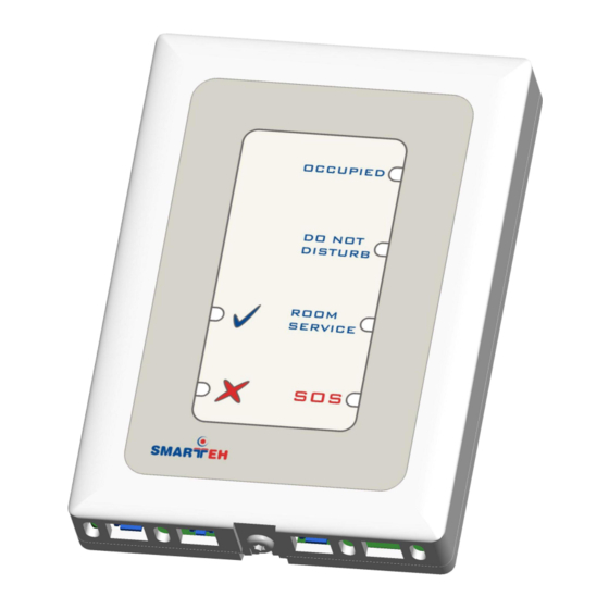
Longo programmable controller LPC-2.ID1 2 FEATURES Figure 1: LPC-2.ID1 special module. Table 1: Technical data RFID identification 4 LEDs for “OCCUPIED”, “DO NOT DISTURB”, “ROOM SERVICE” and “SOS” status OK “ √ ” LED FAULT “ X ” LED Power LED... -
Page 7: Installation
Longo programmable controller LPC-2.ID1 3 INSTALLATION 3.1 Connection scheme Figure 2: Connection scheme... - Page 8 Longo programmable controller LPC-2.ID1 Table 2: K1 K1.1 Ground K1.2 9 V DC Power supply input K1.3 Standard RS-485 A Data receive/send line A K1.4 Standard RS-485 B Data receive/send line B Table 3: K2 K2.1 SPST relay contact Make contact (NO) K2.2...
-
Page 9: Mounting Instructions
Mounting instructions: 1. Mount LPC-2.ID1 module back plate to the provided leveled place on the wall. 2. Fasten 2 screws (DIN 7981 or similar, Φ3 mm, max. head height 3 mm) to fix LPC-2.ID1 module to its place. 3. Connect interconnection cable to the interconnection connector K1. Max. allowed tractive force is 30 N. - Page 10 Longo programmable controller LPC-2.ID1 NOTE: LPC-2.MC3 main control module should be powered separately from other electrical appliance connected to LPC-2 system. Signal wires must be installed separately from power and high voltage wires in accordance with general industry electrical installation standard.
-
Page 11: Module Labeling
Label 2 description: 1. S/N:MC3-S9-0500000190 is the serial number. MC3 – short product name, • S9 – user code (test procedure, e.g. Smarteh person xxx), • 0500000190 – year and current stack code, • 05 – year (last two cyphers), •... -
Page 12: Technical Specifications
Longo programmable controller LPC-2.ID1 4 TECHNICAL SPECIFICATIONS Table 5: Technical specifications Power supply from main module (LPC-2.MC7) Interconnection connector type Berg M Power consumption 0.5 W RFID type Manchester 64, read only Max. reading distance 8 cm Number of outputs 1 SPST –... -
Page 13: Programmers Guide
Longo programmable controller LPC-2.ID1 5 PROGRAMMERS GUIDE Variables There are 22 bytes available for reading and writing from/to ID1 module. While whole frame of 26 bytes is transferred at a time, LPC Manager variables described in the table below are accessed separately. - Page 14 Longo programmable controller LPC-2.ID1 VBOOL8 (#N+2) variable range Relay output command BIT1 BIT2 BIT3 0..1 Received ID OK command Received ID Fault command BIT6 BIT7 VBOOL8 (#N+3)* variable range OCCUPIED LED DO NOT DISTURB LED ROOM SERVICE LED SOS LED 0..1...
-
Page 15: Changes
- updated description about connecting to main module 26.4.2007 - updated connection scheme - updated power supply source 15.3.2006 - Added output isolation description - Added output protection type description - Pollution degree changed to 2 27.3.2005 The initial version, issued as LPC-2.ID1 module User Manual. -
Page 16: Notes
Longo programmable controller LPC-2.ID1 7 NOTES...
Need help?
Do you have a question about the LPC-2.ID1 and is the answer not in the manual?
Questions and answers