
Subscribe to Our Youtube Channel
Related Manuals for Smarteh LPC-2.VV4


Summary of Contents for Smarteh LPC-2.VV4
- Page 1 USER MANUAL Longo programmable controller LPC-2.VV4 dp input output module Version 2 SMARTEH d.o.o. / Poljubinj 114 / 5220 Tolmin / Slovenia / Tel.: +386(0)5 388 44 00 / e-mail: info@smarteh.si / www.smarteh.si...
- Page 2 Longo programmable controller LPC-2.VV4 Written by SMARTEH d.o.o. Copyright © 2023, SMARTEH d.o.o. User Manual Document Version: 2 February, 2024...
- Page 3 Longo programmable controller LPC-2.VV4 STANDARDS PROVISIONS: Standards, recommendations, regulations and provisions of the country in which the devices will operate, must be considered while planning and setting up electrical devices. Work on 100 .. 240 V AC network is allowed for authorized personnel only.
-
Page 4: Table Of Contents
Longo programmable controller LPC-2.VV4 Longo programmable controller LPC-2.VV4 1 ABBREVIATIONS................IV 2 DESCRIPTION...................1 3 FEATURES..................2 4 INSTALLATION..................3 4.1 Connection scheme..............3 4.2 Mounting instructions..............7 4.3 Module labeling................9 5 TECHNICAL SPECIFICATIONS..............10 6 SPARE PARTS..................11 7 CHANGES..................12 8 NOTES..................13... -
Page 5: Abbreviations
Longo programmable controller LPC-2.VV4 1 ABBREVIATIONS Sorted by order of appearance in document: Delta P, pressure difference Variable air volume Input output Negative temperature coefficient Light emitting diode Error Power Normally open Normally closed... -
Page 6: Description
VAV and similar. The LPC-2.VV4 module is powered directly from the LPC-2 main unit. There are two LEDs. Green (PWR) indicates power supply presence, and red (ERR) indicates LPC-2.VV4 module error. -
Page 7: Features
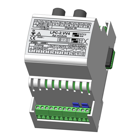
Longo programmable controller LPC-2.VV4 3 FEATURES Figure 1: LPC-2.VV4 module Table 1: Features Powered from LPC-2 main unit DeltaP measurement: 0 .. 500 Pa 3 x Voltage analog inputs: 0 .. 10 V 1 x NTC 10k input 1 x NTC 10k / voltage analog input: 0 .. 10 V, jumper selectable 8 x Digital inputs 1 x Voltage analog output: 0 .. -
Page 8: Installation
Longo programmable controller LPC-2.VV4 4 INSTALLATION 4.1 Connection scheme Figure 2: Connection scheme example... - Page 9 Longo programmable controller LPC-2.VV4 Figure 3: Connection scheme Table 2: Analog Analog.1 EGND Analog.2 Analog input 0 .. 10 V Analog.3 Analog input 0 .. 10 V Analog.4 Analog output 0 .. 10V Table 3: Pressure sensor DeltaP.+ Positive pressure Delta pressure up to 500 Pa DeltaP.-...
- Page 10 Longo programmable controller LPC-2.VV4 Table 4: OUT OUT1.5 Voltage free contacts Normally open relay output OUT1.6 OUT2.7 Voltage free contacts Normally open relay output OUT2.8 OUT3.9 Jumper S2: Normally Open relay output Voltage free contacts Jumper S2: Normally Closed relay output OUT3.10...
- Page 11 Longo programmable controller LPC-2.VV4 Table 7: K1 & K2 Internal BUS Data & DC power supply Table 8: LEDs ON: communication fault LED1: red ERR, Communication status OFF: communication OK ON: power supply OK LED2: green PWR, Power supply status OFF: power supply missing or power off * NOTE: Special care must be taken in case of usage inductive character loads, e.g.
-
Page 12: Mounting Instructions
Longo programmable controller LPC-2.VV4 4.2 Mounting instructions Figure 4: Housing dimensions Dimensions in millimeters. EXTERNAL SWITCH CIRCUIT-BREAKER EXTERNAL OVERCURRENT PROTECTION: The unit is allowed to be connected to installation with over current protection that has nominal value of 16 A or less. - Page 13 Mounting instructions: 1. Switch OFF main power supply. 2. Mount LPC-2.VV4 module to the provided place inside an electrical panel (DIN EN50022-35 rail mounting). 3. Mount other modules. Mount each module to the DIN rail first, then attach modules together through K1 and K2 connectors.
-
Page 14: Module Labeling
EEE – version code (reserved for future HW and/or SW firmware upgrades). ▪ 3. S/N: SSS-RR-YYXXXXXXXXX - serial number. SSS – short product name, ◦ RR – user code (test procedure, e.g. Smarteh person xxx), ◦ YY – year, ◦ XXXXXXXXX– current stack number. -
Page 15: Technical Specifications
Longo programmable controller LPC-2.VV4 5 TECHNICAL SPECIFICATIONS Table 9: Technical specifications Power supply from LPC-2 main module Power consumption 0.5 W Dimensions (W x H x D) 90 x 53 x 77 mm Weight 120 g Maximum altitude 2000 m... -
Page 16: Spare Parts
Longo programmable controller LPC-2.VV4 6 SPARE PARTS For ordering spare parts following Part Numbers should be used: LPC-2.VV4 module LPC-2.VV4 P/N: 225VV422001001 Main modules LPC-2.MM1 P/N: 225MM123001001 LPC-2.MM2 P/N: 225MM223001001... -
Page 17: Changes
Longo programmable controller LPC-2.VV4 7 CHANGES The following table describes all the changes to the document. Date Description 19.02.24 Chapter 2 and figure 2 updated. 27.09.23 The initial version, issues as LPC-2.VV4 User Manual. -
Page 18: Notes
Longo programmable controller LPC-2.VV4 8 NOTES...
Need help?
Do you have a question about the LPC-2.VV4 and is the answer not in the manual?
Questions and answers