
Subscribe to Our Youtube Channel
Related Manuals for Smarteh LPC-2.C06


Summary of Contents for Smarteh LPC-2.C06
- Page 1 USER MANUAL Longo programmable controller LPC-2.C06 Communication terminal Version 1 SMARTEH d.o.o. / Poljubinj 114 / 5220 Tolmin / Slovenia / Tel.: +386(0)5 388 44 00 / e-mail: info@smarteh.si / www.smarteh.si...
- Page 2 Longo programmable controller LPC-2.C06 Written by SMARTEH d.o.o. Copyright © 2020, SMARTEH d.o.o. User Manual Document Version: 1 June, 2020...
- Page 3 24 months is valid from the date of sale to the end buyer, but not more than 36 months after delivery from Smarteh. In case of claims within warranty time, which are based on material malfunctions the producer offers free replacement. The method of return of malfunctioned module, together with description, can be arranged with our authorized representative.
-
Page 4: Table Of Contents
Longo programmable controller LPC-2.C06 Longo programmable controller LPC-2.C06 1 ABBREVIATIONS................1 2 DESCRIPTION...................2 3 FEATURES..................3 4 OPERATION..................4 4.1 Parameters................4 5 INSTALLATION..................7 5.1 Connection scheme..............7 5.2 Mounting instructions..............9 5.3 Module labeling...............11 6 TECHNICAL SPECIFICATIONS..............12 7 CHANGES ..................13 8 NOTES..................14... -
Page 5: Abbreviations
Longo programmable controller LPC-2.C06 1 ABBREVIATIONS Direct Current Transistor-Transistor Logic Receive Transmit UART Universal Asynchronous Receiver-Transmitter... -
Page 6: Description
That way, different communication protocols, which are based on the RS-232, TTL or RS-485 UART protocols, can be implemented, e.g. DMX, proprietary protocols. LPC-2.C06 is controlled and powered from the main module (e.g. LPC-2.MC9) via Right internal bus. -
Page 7: Features
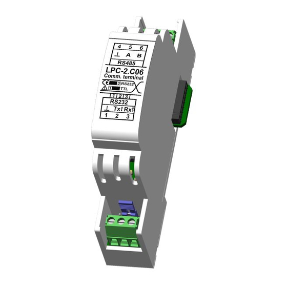
Longo programmable controller LPC-2.C06 3 FEATURES Figure 1: LPC-2.C06 module Table 1: Technical data RS-232 port with possibility to use TTL voltage levels (select-able with jumper) RS-485 port Signal LEDs Supplied from main module Small dimensions and standard DIN EN50022-35 rail mounting... -
Page 8: Operation
Longo programmable controller LPC-2.C06 4 OPERATION Module parameters can be read or written via Smarteh IDE software. 4.1 Parameters Input Protocol type [Protocol_Type]: Protocol type feedback. Intended for future use. Type: USINT 0 .. 255 → 0 .. 255 Raw to engineering data: C session counter [I2C_Session_Cnt]: It changes after each session when data in module updates. - Page 9 Longo programmable controller LPC-2.C06 → Error in reception Maximum receive timeout [Rx_Timeout_Max]: Maximal timeout between received data bytes in received telegram. Type: UINT → Raw to engineering data: 0 .. 65535 0 .. 65535 us Output Selector of protocol type. Intended for future use.
- Page 10 Longo programmable controller LPC-2.C06 Type: USINT → Raw to engineering data: 5 bits → 6 bits → 7 bits → 8 bits (default) → other 8 bits UART stopbits [UART_Stopbits]: Number of stop bits. Type: USINT → Raw to engineering data: 1 bit →...
-
Page 11: Installation
Longo programmable controller LPC-2.C06 5 INSTALLATION 5.1 Connection scheme Figure 2: Connection scheme Table 2: RS485 RS485.4 RS485.5 RS-485 (A) RS-485 standard voltage levels RS485.6 RS-485 (B) Table 3: RS232 RS232.1 → RS232.2 RS-232 (Tx) S1 Position 1-2 (RS232) - Page 12 Longo programmable controller LPC-2.C06 Table 5: K2 Internal BUS Data & DC power supply Connection to I/O module Table 6: S1 – Voltage levels for RS232 port Position 1-2, RS-232 Position 2-3, TTL...
-
Page 13: Mounting Instructions
Mounting instructions: 1. Switch OFF main power supply. 2. Mount LPC-2.C06 module to the provided place inside an electrical panel (DIN EN50022-35 rail mounting). 3. Mount other LPC-2 modules (if required). Mount each module to the DIN rail first, then attach modules together through K1 and K2 connectors. - Page 14 Longo programmable controller LPC-2.C06 Figure 4: Minimum clearances The clearances above must be considered before module mounting.
-
Page 15: Module Labeling
EEE – version code (reserved for future HW and/or SW firmware upgrades). ▪ 3. S/N: SSS-RR-YYXXXXXXXXX - serial number. SSS – short product name, ◦ RR – user code (test procedure, e.g. Smarteh person xxx), ◦ YY – year, ◦ XXXXXXXXX – current stack number. -
Page 16: Technical Specifications
Longo programmable controller LPC-2.C06 6 TECHNICAL SPECIFICATIONS Table 8: Technical specifications Power supply from main module via internal bus Max. power consumption Connection type screw type connector for stranded wire 0.75 to 1.5 mm Dimensions (L x W x H) -
Page 17: Changes
Longo programmable controller LPC-2.C06 7 CHANGES The following table describes all the changes to the document. Date Description 12.06.2020 The initial version, issued as LPC-2.C06 module UserManual. -
Page 18: Notes
Longo programmable controller LPC-2.C06 8 NOTES...
Need help?
Do you have a question about the LPC-2.C06 and is the answer not in the manual?
Questions and answers