
Related Manuals for Smarteh LPC-2.DP1


Summary of Contents for Smarteh LPC-2.DP1
- Page 1 USER MANUAL Longo programmable controller LPC-2.DP1 Temperature Control panel Version 4 SMARTEH d.o.o. / Poljubinj 114 / 5220 Tolmin / Slovenia / Tel.: +386(0)5 388 44 00 / e-mail: info@smarteh.si / www.smarteh.si...
- Page 2 Longo programmable controller LPC-2.DP1 Written by SMARTEH d.o.o. Copyright © 2016, SMARTEH d.o.o. User Manual Document Version: 4 March, 2016...
- Page 3 24 months is valid from the date of sale to the end buyer, but not more than 36 months after delivery from Smarteh. In case of claims within warranty time, which are based on material malfunctions the producer offers free replacement. The method of return of malfunctioned module, together with description, can be arranged with our authorized representative.
-
Page 4: Table Of Contents
Longo programmable controller LPC-2.DP1 Longo programmable controller LPC-2.DP1 1 DESCRIPTION...................1 2 FEATURES..................2 3 OPERATION..................3 3.1 Operational modes..............3 3.2 Functions ................4 3.3 Parameters................5 4 INSTALLATION..................7 4.1 Connection scheme..............7 4.2 Mounting frame selection............9 4.3 Mounting instructions..............10 4.4 Module labeling...............11 5 REGULATION DIAGRAM..............12 6 TECHNICAL SPECIFICATIONS..............13... -
Page 5: Description
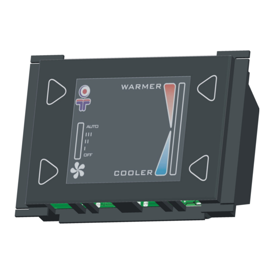
Longo programmable controller LPC-2.DP1 1 DESCRIPTION LPC-2.DP1 control panel (CP) is used for room temperature regulation for systems with Fan speed control (Fan-coil...).. Panel is equipped with temperature and light intensity sensor and four touch buttons (TB). To increase, decrease temperature set point warmer, cooler TB should be pressed respectively. -
Page 6: Features
Longo programmable controller LPC-2.DP1 2 FEATURES Figure 1: LPC-2.DP1 module. Table 1: Features Room temperature measurement 2 touch buttons for temperature set point 2 touch buttons for manual fan speed, auto and controller off 10 position LCD bar-graph for temperature set point... -
Page 7: Operation
Longo programmable controller LPC-2.DP1 3 OPERATION Basic setting can be entered with panel Touch Buttons (TB). Modes of operation and parameters can be set via LPC Manager software, some of them can be also activated through special sequence TB pressing. -
Page 8: Functions
Longo programmable controller LPC-2.DP1 measured by the panel is inside temperature dead band values (default dead band is 0.5 °C). Error In case of CP internal on communication fault, “ERR” sign appear on LCD. When any of four buttons is pressed more than certain time, “SET” sign appear on LCD and buttons functioning is enabled. -
Page 9: Parameters
Longo programmable controller LPC-2.DP1 3.3 Parameters If parameter is set to logical “1”, is considered to be active, enabled or set. If parameter has logical value “0” is considered to be inactive, disabled, or cleared. Parameter can be status, command or both. When parameter is marked as status this means that module is sending information to controller. - Page 10 Longo programmable controller LPC-2.DP1 I regulation par.: Integral parameter for PI calculation algorithm on CP PI Dead band: Value of change for PI loop output. Fan reference: denotes fan speed value requested by panel Temp. SP: This value is taken into PI calculation algorithm Room temp.: Room temperature measured by CP panel.
-
Page 11: Installation
Longo programmable controller LPC-2.DP1 4 INSTALLATION 4.1 Connection scheme Figure 2: Connection scheme... - Page 12 Decrease by one step, step = (Max. temp - Min. temp) * 1/10 (Down-right) Table 4: S1 RS-485 Switch 1 Switch 2 ADDRESS Interconnection cable can ordered from Smarteh or terminated on site, considering wiring scheme bellow: Interconnection cable ICM-X...
-
Page 13: Mounting Frame Selection
Master ● Frames of other vendors most probably suits as well, but they were not verified by Smarteh. Before installation verify compatibility of non listed frames. Module housing has a fin on each side, which can be easily removed with knife cutter or pliers. This adaptation enables housing to be build in various frame formats with two different depths. -
Page 14: Mounting Instructions
Longo programmable controller LPC-2.DP1 4.3 Mounting instructions Figure 3: Housing dimensions Dimensions in milimeters. All connections, module attachments and assembling must be done while module is not connected to the main power supply. Module should be positioned in the wall inside of the room. Avoid direct sunlight or positioning near heating/cooling source object. - Page 15 LPC-2.DP1 is connected to the main module with interconnection cable (e.g., SSK, ICM-7) which must be ordered together with LPC-2.DP1 module. When more modules (e.g., LPC-2.CR1, LPC- 2.CH1, LPC-2.DP2 or up to four LPC-2.DP1) are connected to main module, splitter (e.g., SPL-2) is also required (Figure 2).
-
Page 16: Module Labeling
S/N: DP1-S9-0900000003 is the serial number. • DP1 – short product name, • S9 – user code (test procedure, e.g. Smarteh person xxx), • 10 – year (last two cyphers) • 00000003 – current stack number; previous module would have the stack number •... -
Page 17: Regulation Diagram
Longo programmable controller LPC-2.DP1 5 REGULATION DIAGRAM... -
Page 18: Technical Specifications
Longo programmable controller LPC-2.DP1 6 TECHNICAL SPECIFICATIONS Table 5: Technical specifications Power supply from main module Interconnection connector type RJ-12 6/6 Power consumption Dimensions (W x H x D) 75 x 49 x 29 mm Weight 50 g Maximum altitude... -
Page 19: Changes
The following table describes all the changes to the document. Date Description 30.03.16 Added sentence about sealing junction box and pipes on page 10. 01.07.12 CGP General update. 20.07.10 Updated regulation diagram 01.01.10 The initial version, issued as LPC-2.DP1 module UserManual. -
Page 20: Notes
Longo programmable controller LPC-2.DP1 8 NOTES...
Need help?
Do you have a question about the LPC-2.DP1 and is the answer not in the manual?
Questions and answers