
Subscribe to Our Youtube Channel
Related Manuals for Smarteh LPC-2.MM1


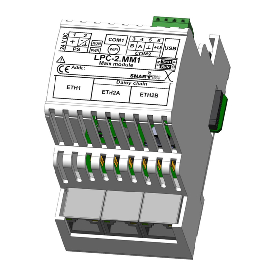
Summary of Contents for Smarteh LPC-2.MM1
- Page 1 USER MANUAL Longo programmable controller LPC-2.MM1 Main module Version 1 SMARTEH d.o.o. / Poljubinj 114 / 5220 Tolmin / Slovenia / Tel.: +386(0) 388 44 00 / e-mail: info@smarteh.si / www.smarteh.si...
- Page 2 Longo programmable controller LPC-2.MM1 Written by SMARTEH d.o.o. Copyright © 2023, SMARTEH d.o.o. User Manual Document Version: 1 December, 2023...
- Page 3 24 months is valid from the date of sale to the end buyer, but not more than 36 months after delivery from Smarteh. In case of claims within warranty time, which are based on material malfunctions the producer offers free replacement. The method of return of malfunctioned module, together with description, can be arranged with our authorized representative.
-
Page 4: Table Of Contents
Longo programmable controller LPC-2.MM1 Longo programmable controller LPC-2.MM1 1 ABBREVIATIONS................1 2 DESCRIPTION...................2 3 FEATURES..................3 4 INSTALLATION..................4 4.1 Connection scheme..............4 4.2 Mounting instructions..............7 4.3 Module labeling................9 5 TECHNICAL SPECIFICATIONS..............10 6 PROGRAMMING GUIDE...............11 6.1 Basic functionalities..............11 6.2 WiFi configuration..............14 7 SPARE PARTS..................16 8 CHANGES ..................17... -
Page 5: Abbreviations
Longo programmable controller LPC-2.MM1 1 ABBREVIATIONS System on module Advanced RISC machines Operating system Transmission control protocol Secure sockets layer International electrotechnical commission Controller area network Communication Universal serial bus USB OTG Universal serial bus On the go Internet protocol... -
Page 6: Description
Ethernet switch. In the case of LPC-2.MM1 and/or local power supply failure, two Ethernet ports will be physically disconnected from the LPC-2.MM1 Ethernet driver and will connect to each other directly. LPC-2.MM1 is also equipped with RS-485 port for Modbus RTU Master or Slave communication with other Modbus RTU equipment. -
Page 7: Features
USB port for debugging and application transfer, USB OTG Modbus RTU Master or Slave Smarteh bus for connection with LPC-2 Smarteh intelligent peripheral modules Remote access and application transfer RTC and 512 kB non-volatile memory with super capacitor for needed energy storage... -
Page 8: Installation
Longo programmable controller LPC-2.MM1 4 INSTALLATION 4.1 Connection scheme Figure 2: Connection scheme... - Page 9 ETH2B RJ-45 shielded, daisy chain functionality Different protocols like Modbus RTU Master can be selected inside Smarteh IDE. Wires connected to the module must have cross sectional area at least 0.14 mm . Use twisted-pair cables of type CAT5+ or better, shielding is recommended. Minimum...
- Page 10 Longo programmable controller LPC-2.MM1 Table 8: Switches ON: RS-485 channel is internally terminated S1.1 COM2 RS-485 termination (Trm) with 1.2 kΩ OFF: no internal termination present ON: PLC in normal operational mode (RUN) S1.2 Operation mode (RUN) OFF: PLC application not running (STOP)
-
Page 11: Mounting Instructions
It must be used as the disconnected device for the equipment. RATING AND CHARACTERISTICS OF FUSES: LPC-2.MM1 main module must be connected with 4 A circuit breaker in Live and Neutral conductor. It is class I unit and must be permanently connected to Protective Earth. - Page 12 Longo programmable controller LPC-2.MM1 Mounting instructions: 1. Switch OFF main power supply. 2. Mount module to the provided place inside an electrical panel (DIN EN50022-35 rail mounting). 3. Mount other IO modules (if required). Mount each module to the DIN rail first, then attach modules together through K1 connector.
-
Page 13: Module Labeling
EEE – version code (reserved for future HW and/or SW firmware upgrades). ▪ 3. S/N: SSS-RR-YYXXXXXXXXX - serial number. SSS – short product name, ◦ RR – user code (test procedure, e.g. Smarteh person xxx), ◦ YY – year, ◦ XXXXXXXXX– current stack number. -
Page 14: Technical Specifications
Longo programmable controller LPC-2.MM1 5 TECHNICAL SPECIFICATIONS Table 10: Technical specifications Rated power supply PS 24 V DC, 2A Operational power supply PS 20 .. 28 V DC up to 24 W depending on additional modules connected Power consumption PS... -
Page 15: Programming Guide
Slave device and as BACnet IP (B-ASC). Modbus TCP/IP master unit When configured for Modbus TCP/IP Master / Client mode, the LPC-2.MM1 functions as a master device, controlling the communications with other slave devices such as sensors, inverters, other PLCs, etc. LPC-2.MM1 sends Modbus TCP/IP commands to and receives Modbus TCP/IP responses from the slave units. - Page 16 Note: each of this commands can read/write up to 246 bytes of data. For analog (Input and Holding registers) this means 123 values, while for digital (Statuses and Coils) this means 1968 values. When higher quantity of data is required, LPC-2.MM1 can execute up to 32 same or different supported commands simultaneous.
- Page 17 Longo programmable controller LPC-2.MM1 BACnet IP unit When configured for BACnet IP (B-ACS), following commands are supported: Data Sharing ReadProperty-B (DS-RP-B) WriteProperty-B (DS-WP-B) Device and Network Management Dynamic Device Binding-B (DM-DDB-B) Dynamic Object Binding-B (DM-DOB-B) Device Communication Control-B (DM-DCC-B) Time Synchronization-B (DM-TS-B) UTCTimeSynchronization-B (DM-UTC-B) For more information, please contact the producer.
-
Page 18: Wifi Configuration
Longo programmable controller LPC-2.MM1 6.2 WiFi configuration 1. Connect module to the PC via USB connector and switch ON power supply. 2. Using web browser, type default IP address 192.168.45.1 and port 8009. 3. Click on “Settings”. Figure 6: Web interface 4. - Page 19 Longo programmable controller LPC-2.MM1 Figure 7: Web interface settings...
-
Page 20: Spare Parts
Longo programmable controller LPC-2.MM1 7 SPARE PARTS For ordering spare parts following Part Numbers should be used: LPC-2.MM1 Main module LPC-2.MM1 P/N: 225MM123001001... -
Page 21: Changes
Longo programmable controller LPC-2.MM1 8 CHANGES The following table describes all the changes to the document. Date Description 19.12.23 The initial version, issued as LPC-2.MM1 User Manual. -
Page 22: Notes
Longo programmable controller LPC-2.MM1 9 NOTES...
Need help?
Do you have a question about the LPC-2.MM1 and is the answer not in the manual?
Questions and answers