Advertisement
Installation · Programming · Operating
Keep this manual safe for reference and future maintenance
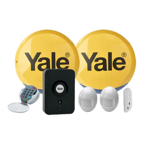
Thank you for choosing the Yale HSA App Alarm kit. This
simple to install system has been designed with the user in
mind.
All the components are self contained and no wired
connections are needed between the units. There is no
need to damage the home decor, lift carpets or run cables.
You can install up to 20 accessories in this system. As well
as extra Door/Window Contacts, PIR Motion Detectors and
Smoke Detectors, you can add Key Fobs for added control
convenience.
Regular testing and battery changes (when notified by the
system) will ensure reliability and peace of mind.
There is no need to seek the services of a qualified
electrician. The Hub is powered by an adaptor and all other
components are powered by battery (all batteries included).
Some accessories are 'tamper' protected. Any
unauthorised tampering with these items when the system
is armed will result in the alarm being triggered.
For more information on this product and Yale Alarm
Range visit www.yale.co.uk
Consumer Support: yale.co.uk/help
The HSA App Alarm Kit does not support PIR Image /
Video cameras, power switch or connection to Yale Smart
Locks. This alarm system is NOT compatible with EF
Series, AC Series & SR series accessories. Compatible
with HSA accessories only.
HSA App
Alarm Kit
HSA6600 - HSA6610
Contents
Recommended Installation Sequence
We recommend you follow the simple install
sequence, headings numbered 1-5.
Information and illustrations are subject to change within this
document. Yale reserves the right to alter the specification and
product design at anytime without notice. Yale® is a registered
trademark. © 2019 ASSA ABLOY. All rights reserved.
2
6
8
10
12
13
15
17
19
Issue No: 1B
Advertisement
Table of Contents


Need help?
Do you have a question about the HSA6600 and is the answer not in the manual?
Questions and answers