
Subscribe to Our Youtube Channel
Related Manuals for EOS ECON H4


Summary of Contents for EOS ECON H4
- Page 1 ECON H4 sauna control unit Installation and operating instruction Made in Germany IP x4 Druck Nr. 29344631en / 49.15...
-
Page 2: Table Of Contents
English content Scope of Delivery ............................4 Technical data ..............................5 General information about using the sauna ..................6 General safety information ........................7 Assembly of the control unit ........................9 Assembly on the wall ..........................9 Assembly in the wall ........................... 10 Connection of the sensor lines ......................11 Assembly of the stove sensor ...................... - Page 3 Activation of the sauna stove ....................25 Deactivation of the sauna stove in Finnish mode .............. 25 Activation of the sauna stove with Life-Guard ..............25 Individual settings ..........................26 Cabin temperature ........................26 Humidity mode for time steps ....................27 Humidity intensity .........................
-
Page 4: Scope Of Delivery
Standard delivery (Subject to change) Included in control unit scope of delivery: 1. Stove sensor board with over-temperature fuse, PTC sensor with sensor housing, two attach- ment screws 3 x 25 mm and sensor cable approx. 2.0 m long. 2. Plastic bag containing three mounting screws 4 x 20 mm. 3. -
Page 5: Technical Data
Technical data • Rated voltage: 400 V 3 N 50 Hz AC • Switch output: max. 9 kW resistive load (AC1 mode) Humidity mode: 6 kW + 3 kW for vaporizer equipment. Can be expan- ded to 36 kW via the connection of power switching devices •... -
Page 6: General Information About Using The Sauna
Dear customer General information You have purchased a high-quality technical Please check whether the unit has arrived in per- device with which you will have years of sauna fect condition. Any transport damages should be fun. This sauna control unit was designed and immediately reported to the freight forwarder inspected according to the current European delivering the goods or you should contact the... -
Page 7: General Safety Information
General safety precautions ature setting. The temperature can be held within operating parameters and This device can be used by children aged • a minimal temperature gradient inside 8 upwards and by persons with physical, the bench area of the sauna cabin can be sensory, or mental disabilities, or who achieved only if unit is assembled correct- have inadequate experience and knowl-... - Page 8 When designing the cabin ensure that the external exposed glass surfaces only reach a maximum temperature of 76°C. If necessary, protective features need to be tted. Attention! Dear customer, according to the valid regulations, the electrical connection of the sauna heater and the control box has to be carried out through the specialist of an authorized electric shop...
-
Page 9: Assembly Of The Control Unit
Fasten the housing bottom at the two bot- Installation of the control unit tom openings (Fig. 4) rmly to the cabin wall. Wall installation The control unit may only be mounted outside the sauna cabin. It is advisable to select the out- ca. -
Page 10: Assembly On The Wall
Recessed installation 1. Cut out a wall section that is at least 3.5 cm deep according to the dimension in Fig. 5. 21 cm Fig. 5 Insert the supplied rubber grommets into the openings at the rear wall of the housing and insert the connecting cables through these openings. -
Page 11: Connection Of The Sensor Lines
Connecting the sensor cables 20 cm You should not install sensor and power supply lines together, or lead them through the same feedthrough. This can lead to interferences in the electronics, such as " uttering" in the re- lays. If it is necessary to lay the cables down together, or if the line is longer than 3m, use a shielded sensor cable (4 x 0.5 mm²). - Page 12 6h, 12h, without restriction Sauna ceiling Centre sensor housing on middle section optional bench sensor optional humidity sen- sor (only Econ H4) Sensor cables Figure 11 Caution! If the lines on plug X2 are confused, this can trigger F2 and da- 142°C...
-
Page 13: Installing The Optional Bench Sensor
Installation of the optio- nal second temperature sensor (bench sensor) Installation place: The bench sensor shall be By faults of the second sensor the following er- mounted to the ceiling over the rear wall bench ror messages will be displayed: opposite to the heater as described in the in- „Sensor break“... -
Page 14: Electrical Connection
For test purposes, the vaporizer is activated for Electrical connection 1 min when the system is switched on. It is only The electrical connection may only be done activated again when the cabin reaches a tempe- by a certi ed electrician in compliance with rature that is 10K below the target temperature. -
Page 15: Installation Diagram
Installation diagram optional = optional oder ECON max. 3 kW 400 V 3 N AC 50 Hz The control lamp for public systems without heat-up time restriction must be installed in the supervisor's room. Terminal arrangement on the circuit board Sauna bus Plug for sensor connection Connection... -
Page 16: Wiring Diagram Sauna Heater Up To 9 Kw
Connecting the sauna heater (max. 9 kW) 142°C ECON L1 L2 L3 Lü V1 N S1 Limiter weiß / white Sensor rot / red max. 100 W max. 100 W P max. 9 kW max. 3000W 400 V 3 N AC 50 Hz Caution: Always connect the neutral conductor (N) of the sauna stove. -
Page 17: Wiring Diagram Vaporizer
Connection of vaporizer CAUTION: When the vaporizer is activated, the output ECON L1 L2 L3 "W" from the sauna heater is switched to Lü V1 N S1 the terminal "Wb" to the vaporizer. In this case, the sauna heater heats only with two thirds of the power. -
Page 18: Operation
Operation Once the system has been installed with all components and all covers have been xed, you can put your sauna unit into operation. Over the following pages we will show you the options provided to you with the control. Generalities The user interface MODE... -
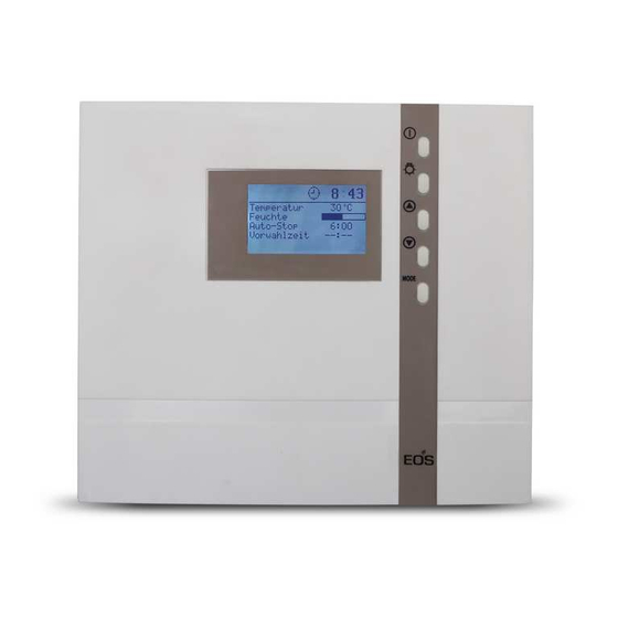
Page 19: Basic Stand By Screen
Default display Stand-by is shown if the system is in Stand-by mode. 12:00 Temperatur 30°C The system also returns to this screen from Feuchte other menu items, if there is no activity for >15 Auto-Stop 5 : 59 - - : - - Vorwahlzeit seconds. -
Page 20: Cabin Lighting
To adapt the individual values to the respec- tive requirements, the button must be MODE pressed brie y from the standby screen. 12:15 Temperatur 30°C Those parameters that can be changed are Feuchte shown in black and the required parameters Auto-Stop 5 : 59 - - : - -... -
Page 21: Fans
The cabin lighting can be dimmed and saves > 3 s this value separately for operation mode and 12:15 standby mode. To change the value for the standby, press the light button in standby for >3s until the light symbol appears with a bar in the display. -
Page 22: Initial Commissioning
Initial commissioning 12:15 Life - Guard 12:00 12:15 Life - Guard 12:00 > 3 s MODE > 3 s MODE 12:15 00:00 Tageszeit : 00 00:00 Tageszeit 12:15 : 00 MODE 00:00 > 3 s MODE Tageszeit 12 : 12:00 Temperatur 30°C Feuchte... -
Page 23: Changing The Language
Change language Change time 12:00 12:00 Temperatur 30°C Temperature 30°C Humidity Feuchte Auto-stop Auto-Stop 5 : 59 5 : 59 - - : - - - - : - - Start time Vorwahlzeit & MODE & MODE 12:00 12:15 Tageszeit Time of day 12 : 00 12 : 15... -
Page 24: Activating The Life-Guard
Activating the Life - Guard Activate / deactivate the child lock Life - Guard is a settable relatively short time, If the child lock is activated (the key symbol is e.g. 20 minutes, after which the sauna unit is visible in the top section of the display) only the switched o , except for the cabin lighting. -
Page 25: Activation Of The Sauna Stove
Switching on the sauna unit Activation of the sauna system with Life-Guard 12:00 12:00 Temperatur 30°C Temperatur 30°C Feuchte Feuchte Auto-Stop Auto-Stop 5 : 59 5 : 59 - - : - - - - : - - Vorwahlzeit Vorwahlzeit 20 min Life - Guard >... -
Page 26: Individual Settings
Individual Settings The following are options for adapting the control systems to your individual needs. The various parameters can be changed in standby or in operation mode and the changes are saved in the device. Changes made in operation mode are implemented immediately. Setting range: Dry sauna operation 30 - 115°C Cabin temperature... -
Page 27: Humidity Mode For Time Steps
Humidity mode for time you the temperature values via the relative air humidity for the most common sauna shapes steps (without humidity and comfort zones. sensor) A prerequisite for humidity mode is the connec- tion of a suitable vaporizer device up to max. 3 Temperature in °C kW at 230 V AC. - Page 28 Humidity intensity (time steps) If a value is entered here the sauna unit automatically goes into humidity operation when switched on. In Stand-by In operation 12:00 12:15 Temperatur 30°C Temperatur 30°C Feuchte Feuchte Auto-Stop 5 : 59 Auto-Stop 5 : 59 - - : - - Vorwahlzeit - - : - -...
-
Page 29: Humidity Mode For Humidity Sensor
Humidity mode for connected humidity sensor Humidity intensity: If a value is entered here the sauna unit automatically goes into humidity operation when switched on. In Stand-by In operation 12:00 12:15 Temperatur 30°C Temperatur 30°C Feuchte Feuchte Auto-Stop 5 : 59 Auto-Stop 5 : 59 - - : - -... -
Page 30: Deactivation Of The Sauna System In Humidity Mode
The humidity intensity shown in the display Switching o the sauna unit during corresponds to the relative humidity around humidity operation the humidity sensor if this is connected. The To dry out the sauna cabin after the humidity relative humidity is set or shown in the display. mode, a residual heat phase is activated after This is explained in the diagram. -
Page 31: Auto-Stop
Auto-stop / heat-up time restriction Auto-Stop is the time to which the heating time is limited. The sauna unit automatically turns o once this time has expired. Depending on the con guration of the control unit, a time between 00:01 and 6:00 or 12:00 hours can be set (see page 31). - Page 32 12:15 12:15 Temperatur 30°C Temperatur 30°C Feuchte Feuchte Auto-Stop Auto-Stop - - : - - - - : - - Vorwahlzeit Vorwahlzeit > 3 s > 3 s MODE MODE 12:15 12:15 Temperatur 30°C Temperatur 30°C Feuchte Feuchte Auto-Stop Auto-Stop 3 : 30 3 : 30 - - : - -...
-
Page 33: Preselection Time
Preselection time The preselection time is used to pre-select the activation time of your sauna stove within 24 hours. Always make sure that there are no objects on the sauna unit before the heating process begins. Risk of re!! Please remember however that the cabin must heat up for approx. 40-50 minutes in order to achieve a pleasant climate in the cabin. -
Page 34: Activation Of The Preselection Time
12:15 12:15 Temperatur 30°C Temperatur 30°C Feuchte Feuchte Auto-Stop Auto-Stop 5 : 59 5 : 59 17 : Vorwahlzeit Vorwahlzeit 17 : 12:15 12:15 Temperatur 30°C Temperatur 30°C Feuchte Feuchte Auto-Stop 5 : 59 Auto-Stop 5 : 59 Vorwahlzeit 17 : Vorwahlzeit 17 : >... -
Page 35: Life-Guard
Life-Guard Here you can set the time after which the sauna system should be deactivated and reactivated again for the Life-Guard time by pressing the button. MODE This setting can only be made in standby mode if the Life-Guard function is active. In Stand-by 12:00 12:00... -
Page 36: Extend Heat-Up Time Restriction
Extend heat-up time restriction / replace device fuse By altering a jumper you can extend the heat-up restriction from 6:00 (standard) to 12:00 hours or "inde nite". Please note that extensions are only allowed in certain commercially operated sauna systems. Only allow a specialist to carry out this work. -
Page 37: Error Messages
Error messages The control unit continuously monitors the sensor for short circuits and interruptions. At the same time, the system checks to ensure that there is enough water in the vaporizer tank. The error messages appear as follows: Display Cause Remedy = interrupted room sensor circuit Arrange for a specialist to... -
Page 38: The Device Switch (Switch-Off )
The device „Switch-o “ switch Switch-o by ECON control units You will nd the rocker switch on the top side of the control unit. You can completely discon- nect the control unit from the mains using this switch. Switch-o Unit turned on (default Position I) Press the switch on the left side of the rocker Unit fully switched o... -
Page 39: Manual Specification Of The Lighting
Manual specifi cation of the lighting: The control system recognises inductive loads via a voltage rise and then switches from phase control to phase cut-off. If there are recognition problems, the phase control type can be defi ned manually. Only a specialist from an authorised specialist company may carry out this work! 1. -
Page 40: Holiday Home Mode
Holiday home mode The holiday home mode allows the control system to be blocked so that only the most necessary functions are visible and the lan- guage for the menu needs to be selected every time before use. The holiday home mode is activated and de- activated by keeping the Up+Down buttons pressed whilst switching on via Switch-Off. -
Page 41: Recycling
Outside of Germany please contact your spe- Service Address: cialist dealer in case of warranty claims. Direct warranty processing with our service depart- EOS Saunatechnik GmbH ment is in this case not possible. Schneiderstriesch 1 Equipment commissioning date: 35759 Driedorf, Germany... -
Page 42: General Terms And Conditions Of Service
General Terms and Conditions of Service shipments via parcel post. The manufacturer shall accept no liability for damage incurred as a result of improper I. Scope packaging in an individual shipment. Unless otherwise agreed in writing in a speci c case, the- VI.
Need help?
Do you have a question about the ECON H4 and is the answer not in the manual?
Questions and answers