
Subscribe to Our Youtube Channel
Related Manuals for EOS ECON H3


Summary of Contents for EOS ECON H3
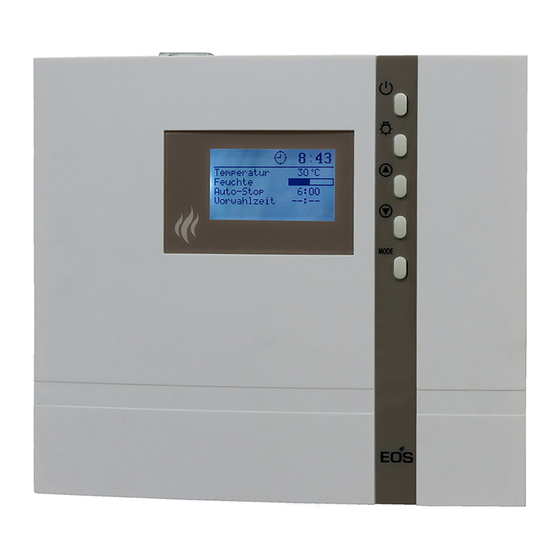
- Page 1 ECON H3 Sauna control unit Installation and operating instruction Made in Germany IP x4 Druck Nr. 29344533en 22.13...
-
Page 2: Table Of Contents
English Table of Contents Scope of delivery ............................4 Technical specifications ..........................4 General information about sauna bathing ..................5 General safety precautions ........................6 Mechanical installation of the control unit Installation place .............................8 Surface-mounting installation ......................8 Semi-recessed installation ........................9 Connecting the temperature sensor cables ..................10 Installation and connection of the temperature sensor ............ - Page 3 Switching on the sauna heater ....................22 Switching off the sauna heater ....................22 Switching on the sauna heater with Life - Guard ............... 22 Individual settings ..........................23 Cabin temperature ........................24 Life - Guard ............................24 Auto-Stop (heating time limitation) ..................25 Preselection time (pre-set timer) ....................
-
Page 4: Scope Of Delivery
Scope of delivery (changes without prior notice reserved) The package contents includes: 1. Control unit 2. Temperature sensor, consisiting of: sensor board with overheating protection fuse, KTY- sensor, sensor housing, two 3x25 mm fastening screws and 2,0 m sensor cable. 3. - Page 5 Dear customer General information You have purchased a high-quality technical Please check whether the unit has arrived in per- device with which you will have years of sauna fect condition. Any transport damages should be fun. This sauna control unit was designed and immediately reported to the freight forwarder inspected according to the current European delivering the goods or you should contact the...
-
Page 6: General Safety Precautions
General safety precautions ature setting. The temperature can be held within operating parameters and This device can be used by children aged 8 a minimal temperature gradient inside upwards and by persons with physical, the bench area of the sauna cabin can be sensory, or mental disabilities, or who achieved only if unit is assembled correct- have inadequate experience and knowl-... - Page 7 When using control units that o er the possibility of external access (GSM-module, remote button, etc.) or time-delayed switching (preselection time, weekly timer, or similar) a trig- ger guard with covered heating unit is required. (cover protection type 1-5 or S-Guard).
-
Page 8: Surface-Mounting Installation
Fasten the housing bottom at the two bot- Installation of the control unit tom openings (Fig. 4) rmly to the cabin wall. Wall installation The control unit may only be mounted outside the sauna cabin. It is advisable to select the out- side wall of the cabin to which the sauna heater is xed from the inside as mounting position. - Page 9 Recessed installation 1. Cut out a wall section that is at least 3.5 cm deep according to the dimension in Fig. 5. Fig. 5 Insert the supplied rubber grommets into the openings at the rear wall of the housing and insert the connecting cables through these openings.
- Page 10 2. Drill a hole in sauna ceiling panel to lead the Connection of the sensor cables cable through, preferably through the mid- You should not lay sensor and power supply ca- dle of one of the wooden boards. bles together, or draw them through the same 3.
- Page 11 6 h, 12 h, unlimited Sauna ceiling centre sensor housing in the middle of the plank Second temperature sensor (optional) Humidity sensor (op- tional, only Econ H3) sensor cables Fig. 11 142°C Limiter Sensor Attention! Make sure not to confuse...
- Page 12 Installation of the optio- nal second temperature sensor (bench sensor) Installation place: The bench sensor shall be By faults of the second sensor the following er- mounted to the ceiling over the rear wall bench ror messages will be displayed: opposite to the heater as described in the in- „Sensor break“...
-
Page 13: Electrical Connections
Electrical connections Connecting the vaporizer The electrical connection may only be done by a certi ed electrician in compliance with the guidelines of the local utility company To connect the vaporizer, use silicone connect- and the VDE. ing lines 4 x 1,5 mm² as well. In general, there may be only one xed connec- tion to the network;... -
Page 14: Installation Diagram
Installation diagram optional = alternativ oder ECON max. 3 kW 400 V 3 N AC 50 Hz A control lamp indicating active heating must be installed in the room or location of supervising sta by commercial sauna cabins with disabled heating time limitation. Terminal arrangement on the circuit board. - Page 15 Connecting the sauna heater (max. 9 kW) Limiter 142°C Sensor ECON L1 L2 L3 max. 100 W max. 100 W P max. 9 kW max. 3000 W 400 V 3 N AC 50 Hz Warning: Always connect the neutral terminal (N) of the sauna oven. During steam operation, one phase of the oven is switched o ;...
-
Page 16: Connection Of The Vaporizer
Connection of the vaporizer Caution: When ECON L1 L2 L3 connecting the vapor- izer the output “W” is switched from the sauna heater to the terminal “Wb” to the vaporizer. In this case, the sauna heater heats only with two thirds of the power. 400 V 3 N AC 50 Hz max. -
Page 17: Operation
Operation Once the control unit has been installed with all components and all covers have been xed, you can put your sauna unit into operation. The following pages provide the detailed explanation, how to operate your control panel and make all necessary settings. General details Operation elements MODE... -
Page 18: Interface In Stand-By
Interface in Stand by is shown if the control unit is in stand-by model 12:00 Temperature 30°C The display will automatically switch this in- Auto-stop 5 : 59 terface from any state if no button has been Start time - - : - - pressed within >15 Sek. -
Page 19: Cabin Lighting
In order to adjust the individual values to the particular desires, brie y push the -but- MODE ton out of Stand-by. 12:15 The modi able parameter will then be high- Temperature 30°C Humidity lighted in black and it is possible to select with Auto-stop 5 : 59 - - : - -... -
Page 20: Initial Commissioning
Initial commissioning 12:00 12:15 Life - Guard 12:00 12:15 > 3 Sec Life - Guard MODE 00:00 Time of day > 3 Sec MODE : 00 12:00 Temperature 30°C Humidity Auto-stop 5 : 59 - - : - - Start time 00:00 Time of day : 00... -
Page 21: Change Language
Change language Set (change) time 12:00 12:00 Temperature 30°C Temperature 30°C Humidity Humidity Auto-stop 5 : 59 Auto-stop 5 : 59 - - : - - - - : - - Start time Start time & & MODE MODE 12:00 12:15 Tageszeit Time of day... -
Page 22: Activate The Life - Guard
Activating the Life - Guard Activate / deactivate the child lock Life - Guard is a settable relatively short time, If the child lock is activated (the key symbol is e.g. 20 minutes, after which the sauna unit is visible in the top section of the display) only the switched o , except for the cabin lighting. -
Page 23: Life - Guard
Switching on the sauna unit Switching on the sauna unit with Life - Guard 12:00 12:00 Temperature Temperature 30°C 30°C Humidity Humidity Auto-stop Auto-stop 5 : 59 5 : 59 - - : - - - - : - - Start time Start time 20 min... -
Page 24: Individual Settings
Individual settings Hereafter we are showing you options that allow you to adjust the controls to your individual needs. The various parameters can be changed in Stand-by or in operation and the changes are saved in the unit. Changes made in operation are e ective directly. Setting range: Finnish mode 30 - 115°C Cabin temperature... -
Page 25: Cabin Temperature
air humidity temperature values for the stand- Humid mode operation ard bath forms and comfort zones. Temperature in °C The prerequisite for humidity operation is the connection of a suitable vaporizer unit up to Sauna max. 3 kW to 230 V AC. The control unit will switch the vaporizer, depending on the set hu- midity value (proportional or rel. - Page 26 If a value is entered here the sauna unit automatically Humidity regulation goes into humidity operation when switched on. (propotional to time): In stand-by In operation 12:00 12:15 Temperature 30°C Temperature 30°C Humidity Humidity Auto-stop 5 : 59 Auto-stop 5 : 59 - - : - - Start time - - : - -...
- Page 27 Humidity regulation (by connected humidity sensor) If a value is entered here the sauna unit automatically goes into humidity operation when switched on. In stand-by In operation 12:00 12:15 Temperature 30°C Temperature 30°C Humidity Humidity Auto-stop 5 : 59 Auto-stop 5 : 59 - - : - - Start time...
- Page 28 The humdity intensity shown on the display Switching o the sauna in humid by connected humidity sensor corresponds to mode the relative humidity of the air in % around the In order to get the sauna cabin dry after humid humdity sensor.
- Page 29 Auto-Stop Auto-Stop is the time to which the heating time is limited. The sauna unit automatically turns o once this time has expired. Depending on the con guration of the control, the time is adjustable from 0:01 to 6:00, to 12:00 hours or to 24 hours (unlimited mode).
- Page 30 12:15 12:15 Temperature 30°C Temperature 30°C Humidity Humidity Auto-stop Auto-stop - - : - - - - : - - Start time Start time > 3 sec > 3 sec MODE MODE 12:15 12:15 Temperature 30°C Temperature 30°C Humidity Humidity Auto-stop 3 : 30 Auto-stop...
- Page 31 Time preseltion Using the time preselection, you can preselect a switch-on time within 24 hours for your sauna heater. See page 34 for more details. Always make sure that there are no objects on the sauna unit before the heating process begins. Fire risk! Please remember however that the cabin must heat up for approx.
-
Page 32: Activate The Preselection Time
12:15 12:15 Temperature 30°C Temperature 30°C Humidity Humidity Auto-stop 5 : 59 Auto-stop 5 : 59 17 : Start time Start time 17 : 12:15 12:15 Temperature 30°C Temperature 30°C Humidity Humidity Auto-stop 5 : 59 Auto-stop 5 : 59 Start time 17 : Start time... - Page 33 Life-Guard Here you can set a short period of time after which the sauna will be automatically switched o (interrupted) and may be immediately restarted for the same period of time by pressing the MODE button. The setting of the „Life-Guard“ time may be made only in stand-by mode. The „Life-Guard“ func- tion must be activated in the basic set-up menu and shown on the display.
-
Page 34: Extend The Time Setting For Sauna Time
Extension of the heating time limitation By switching a jumper you can extend the time setting for sauna time from 6:00 to 12:00 hours or to unlimited operation time. Please notice that such extension is only permitted for certain com- mercial sauna cabins and may be restricted by the local legal regulations. -
Page 35: Error Messages And Troubleshooting
Error messages and troubleshooting The control unit continuously monitors the sensors for short circuits and interruptions. The error messages appear as follows: Display Cause Remedy Have cables and KTY che- = Interruption in the room sensor circuit. 12:00 cked by an expert. KTY at The temperature sensor (KTY) is de- 20°C shall have ca. -
Page 36: The Device Switch (Switch-Off )
The device „Switch-o “ switch Switch-o by ECON control units You will nd the rocker switch on the top side of the control unit. You can completely discon- nect the control unit from the mains using this switch. Switch-o Unit turned on (default Position I) Press the switch on the left side of the rocker Unit fully switched o... -
Page 37: Service Address
Outside of Germany please contact your spe- cialist dealer in case of warranty claims. Direct Service Address: warranty processing with our service depart- EOS Saunatechnik GmbH ment is in this case not possible. Adolf-Weiß-Straße 43 Equipment commissioning date: 35759 Driedorf-Mademühlen, Germany... -
Page 38: Handling Procedures For Return Shipments (Rma) - Details For All Returns
Handling procedures for return shipments (RMA) - Details for all returns ! Dear customer we hope that you will be satis ed with the purchased EOS product. In the rear case if you may have a claim and will need to return a product, please follow the procedures speci ed below.
Need help?
Do you have a question about the ECON H3 and is the answer not in the manual?
Questions and answers